08/19/2020 Author: VT-METALL
Issues discussed in the material:
- Metal turning technology
- Metal turning equipment
- Cutting tools for metal turning
- Types and causes of defects after metal turning
- Safety precautions when turning metal
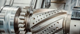
Metal turning is one of the most popular technologies for manufacturing parts using special equipment. It is based on a method for removing excess layers from a workpiece to make it meet the specified parameters.
Turning allows you to produce various parts from most known metals: steel, copper, titanium, bronze and many others. In our article we will talk about the basic principles of this technology, describe the equipment and tools, and also analyze the types of defects and ways to prevent them.
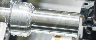
Metal turning technology
For metal turning, you need equipment equipped with cutting tools such as drills, cutters, reamers, etc. By acting on the workpiece, they remove layers of metal of a given thickness from it. The technology of turning requires the execution of both the main movement, that is, the rotation of the part that is mounted on the faceplate (chuck), and the feed movement. The cutting tool continues to perform the latter (that is, feed) until a product with the specified dimensions (shape, surface finish) is obtained.
There are a large number of techniques that allow you to combine the two movements described (main and serve). This makes it possible to process workpieces of various configurations on lathes. In addition, turning equipment allows you to perform such technological operations as:
- cutting different threads;
- work with holes (drilling, boring, countersinking, reaming);
- cutting the workpiece;
- creating grooves of different configurations along the surface of the part.
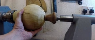
The equipment has great functionality, which allows you to perform various types of metal turning, including working with the following products:
- nuts;
- shafts of various configurations;
- bushings;
- rings;
- gears;
- couplings;
- pulleys.
The production of products using turning equipment involves obtaining high-quality products. Quality implies compliance with the specified shapes, sizes, location accuracy and degree of roughness of all surfaces of the finished product.
We recommend articles on metalworking
- Steel grades: classification and interpretation
- Aluminum grades and areas of their application
- Defects in metal products: causes and search methods
Cutting modes: what are they?
This is a whole complex of characteristics that determine the conditions for carrying out a turning operation. According to the technological routes, the processing of any element (especially complex in shape) is carried out in several transitions, each of which requires its own drawings, dimensions and tolerances, equipment and accessories. Having calculated and/or selected all these parameters once for the first workpiece, in the future you will be able to substitute them by default - when producing the second, fifth, hundredth part - and thus minimize the time for preparing the machine and simplify quality control, that is, optimize the production process .
The main indicators include depth, speed, feed, the list of additional ones includes the mass of the object, allowances, the frequency with which the spindle rotates, and, in principle, any characteristic that affects the result of processing. And it is important to choose those that will provide the best final accuracy, roughness and economic feasibility.
There are several ways to calculate cutting conditions when turning:
The first is quite accurate and, before the advent of powerful computer technology, was considered the most convenient. According to it, all calculations were carried out on the basis of the equipment’s passport data: engine power, spindle speed and other indicators were substituted into already verified empirical expressions and the required characteristics were obtained.
With the development of specialized software, the calculation task has been significantly simplified - all operations are performed by a machine, faster than a person and with a much lower probability of making mistakes.
When you don’t have a computer or formulas at hand, but you do have experience, you can determine the appropriate criteria based on normative and reference data from the tables. But for this it is necessary to take into account all changes in values, even the slightest, which is not always convenient in production conditions.
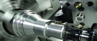
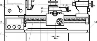
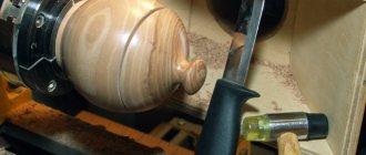
Metal turning equipment
Metal turning should be carried out on machines that can be divided into groups depending on the products they produce and their accuracy:
- Turning and screw-cutting equipment. This group includes the most common equipment used to create cone-shaped products, cylindrical surfaces of various diameters, make carvings, and process non-ferrous and ferrous metals.
- Turning and rotary equipment. These are machines that are capable of producing parts of large diameters, and also, similar to the previous ones, working with non-ferrous and ferrous metals.
- Lathe equipment. Suitable for creating cylindrical and conical products. Unlike others, on such machines the workpiece is installed horizontally.
- Turning and turret equipment. Used when working with a calibrated pond.
In addition to the above, there is equipment that has a narrow specialization. It can only conditionally be classified as a lathe, since workpieces are cut using cutters.
- Introduction of CNC into the operation of machine tools.
The use of a numerical control (CNC) system gave a significant impetus to the development of machine tool industry. Metal turning on CNC machines has provided an opportunity to reduce the cost of the resulting products, and the accuracy and cleanliness of material processing has increased.
CNC allows you to achieve the following results:
- increased productivity when using cutters equipped with a cutting edge made of carbide;
- the ability to process products made of non-ferrous, ferrous metals and tool steels with the correct equipment;
- process automation with minimal intervention from a technician;
- the ability to include any types of cutting in the CNC program, and with a predetermined cutting speed and feed;
- increased process safety, since the use of equipment without a protective casing is blocked by the machine program;
- increasing the accuracy of work due to cutting at a certain speed, as a result of which the volume of scrap of critical parts of structures is reduced.
Numerical control is widely used on machines manufactured in China and the USA. CNC can only be installed on equipment whose parts positioning accuracy is quite high.
Characteristics of cutting conditions
Before we consider all the main parameters in detail, let’s say a few more words about calculation methods. More precisely, about how they moved from graphics to analytics and computerization.
As production improved, even the most detailed tables turned out to be less and less convenient: columns, columns, ratios - it took a huge amount of time to study this and find the right value. And this despite the fact that the main indicators are interconnected, and a decrease/increase in one of them provoked changes in the others.
Having established such an obvious dependence, engineers began to use the analytical method, that is, they thought through empirical formulas, and began to substitute spindle speed, power of the power unit and feed into them and find the necessary characteristics. Well, the development of computers and the emergence of computing software seriously simplified the task and protected the final results from human errors.
Types and causes of defects after metal turning
During turning of parts, defects may occur. It could be:
- Non-compliance with the surface roughness specified in the design documentation.
- Ovality of the shape of the treated surface.
- The conical shape of the resulting surface.
- Distortion of the dimensions of a part during turning.
- The presence of a partially untreated surface of the product.
Now let's take a closer look at the listed types.
- The surface roughness differs from the specified one.
There are several reasons for this defect:
- The feed is too large.
- The workpiece shakes quite a lot due to poor fastening or because the spindle bearing is worn out.
- The gap between different elements of the caliper has been increased.
- The cutter is not secured sufficiently.
- Excessively small radius of curvature of the cutter.
- Poor sharpening of the tool.
- High viscosity of the processed material.
- Incorrect cutter geometry.
All previously listed types of defects are corrected by removing the thinnest layers of material from the parts.
- Ovality of the shape of the treated surface.
The surface of the part becomes oval due to spindle runout. This may happen due to:
- The bearing wears out unevenly.
- The spindle journal wears unevenly.
- Dirt and/or small chips get into the conical bore of the spindle.
The described problems are eliminated if:
- regular inspections of equipment;
- timely maintenance and repair;
- cleaning conical holes and anterior centers.
- The conical shape of the resulting surface.
The occurrence of such a defect is associated with a displacement of the posterior center relative to the anterior one. This happens due to the penetration of dirt and small waste into the rear hole of the quill. You can get rid of marriage with the help of:
- correct installation of the rear center;
- cleaning the conical hole of the quill and the center;
- changing the location of the tailstock shell on the plate where it is located (if necessary).
- Distortion of the dimensions of a part during turning.
The discrepancy between the dimensions occurs due to the fact that:
- the cutting depth was not set accurately;
- The test chip measurements were taken incorrectly.
Unfortunately, it is impossible to fix a part with a diameter that is smaller than the required one. If it is larger, then it is necessary to remove the calculated layer of material from the workpiece.
Cutting speed and its calculation
One of the most important indicators is speed. Its value directly depends on the work performed. At maximum speed, the ends of the workpieces are trimmed. Turning or drilling have different requirements for this parameter.
To select the optimal speed value and perform high-quality processing of the part, you should consider:
The cutting speed for traditional methods of influencing parts can be determined using the corresponding tables from reference books. But in production conditions it is not always advisable to resort to this option. It is much faster to calculate the value of this parameter using a simple formula:
V – desired speed, m/min;
D – maximum diameter of the workpiece used, mm;
n – the number of revolutions of the part in one minute, corresponding to the machine spindle speed;
π is a constant equal to 3.141526.
This shows that the processing speed is directly proportional to the diameter of the original workpiece. And the smaller it is, the higher the rotation speed should be.
When choosing and assigning one or another mode of operation of a lathe, it is necessary to take into account the hardness of the cutters and the material of the part. For example, when machining with carbide cutters, the recommended value should be in the range of 100–200 m/min.
With a known value, the required cutting frequency can be easily calculated from the above formula.
The processing depth is selected taking into account the drive power and cutting tool material. If parasitic vibrations appear during operation, the cutter feed speed should be reduced.
Safety precautions when turning metal
Certain safety precautions must be observed when performing operations on turning equipment. Otherwise, you can damage the product, break the cutter, or get injured:
- We must not forget about protective work clothing. The kit should include: a robe, a headdress, fully closed shoes, and safety glasses. Neglect of equipment can lead to burns and wounds from chips and flying metal fragments.
- You cannot work with gloves!
- The cutters must be well sharpened and, when using a lathe, centered and secured.
- You need to hold the chisels firmly with both hands when working with them.
- It is imperative to rough the workpiece before shaping it.
- You cannot be distracted and leave the working machine unattended.
- You shouldn’t rush, you need to correctly calculate your strength when feeding manually.
Working metal on a lathe requires practice. Each new machine must be mastered, and different operations must be tried on defective workpieces. This will provide an opportunity to understand the characteristics of the equipment, gain greater accuracy and achieve increased productivity. By following the recommendations listed above, you can get excellent results and also avoid defects and injuries.