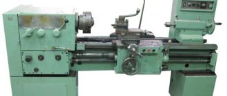
Screw-cutting lathe
Lightweight screw-cutting lathe. Accuracy class – P (increased accuracy). Climatic modification U.4.1. Not built into an automatic line.
Purpose, scope
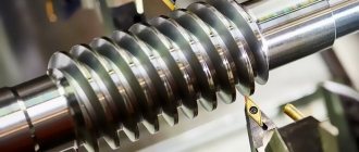
This type of equipment has shown good performance in small workshops, PARM. It is possible to cut all types of threads except pitch threads. Machining of parts in centers, collet, chuck or faceplate. Mainly used for repair work.
Technical indicators
Workpiece parameters:
- diameter above the bed – up to 250 mm;
- diameter above the caliper – up to 145 mm;
- rod diameter – 25 mm.
Spindle parameters:
- spindle speed varies from 30 to 3000 rpm;
- hole diameter – 26 mm.
Technical indicators
This machine has relatively small dimensions:
- height – 1.36 m;
- length – 1.51 m;
- width – 0.72 m;
- weight – 765 kg.
The design of the mechanisms allows you to create 3 types of threads: metric, inch and modular. The number of feeds on the machine is 28. The spindle is made with a hole of 2.6 cm, and the number of its revolutions is in the range of 30 - 3000 rpm. The design also provides for spindle braking.
The maximum diameter of the workpiece processed above the bed is up to 25 cm, and above the support – 14.5 cm. The gap between centers is 50 cm. The maximum diameter of the rod is 2.5 cm, and the maximum length of the part being worked on should not exceed half a meter .
Thanks to all the technical capabilities listed above, this device is classified as a machine with increased precision. The dimensions of the machine and the features of its functioning are best suited for small repair and mobile workshops.
Design features
A special feature is the presence of a variator. It allows you to change the spindle speed. The rotation of the main engine through a V-belt system and a gear coupling transmits the rotation of the spindle to the variator input shaft. The change in speed occurs due to a change in the distance between the conical disks.
By reducing the gap, the discs push the V-belt to the edge and the diameter of the pulley increases. The gear ratio increases - the spindle speed increases. The same design is used on the variator output shaft.
Placing the variator on the frame without connection with the stand and installing the apron on an independent suspension reduces the vibration level. The use of precision bearings and the rigidity of the machine structure ensure precise processing of parts.
The feed box allows you to cut threads in the range of:
- metric (in mm) from 0.2 to 28;
- modular (in mod) from 0.1 to 14;
- inch (threads per inch) from 5 to 96.
Changing the speed of longitudinal and transverse feeds without changing the gears in the guitar.
Dimensions and weight
Overall size: 0.725m x 1.36m x 1.51m.
Weight in kg – 765.
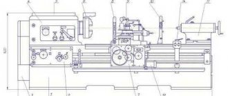
Location of components
- The cabinet contains inside a lubrication mechanism, a main drive, a variator, and a box with electrical equipment. The cabinet is mounted on a frame with a level adjustment mechanism.
- The bed is fixed in the upper part of the cabinet. It houses the headstock, tailstock and apron.
- The headstock includes the spindle assembly, guitar and feed box.
- The apron is equipped with a support with a tool holder, a mechanism for longitudinal and transverse feeds, and a protective shield.
- The tailstock moves along the frame guides and is secured with bolts.
Control structure
The controls are located on the front of the machine and are grouped where the mechanisms they control are located.
The variator is controlled:
- The variator speed shift knob (switches the spindle speed ranges).
- The flywheel changes the spindle speed (the spindle speed is smoothly controlled by moving the sliding disk of the planetary gear).
- Spindle rotation control handle (switches the direction of spindle rotation).
On the front side of the headstock casing there are switches for controlling speed selection, a link for increasing the thread pitch, reversing the feed drive, switching feeds, turning on the lead screw and roller, and switching feeds.
These elements control the gearbox and the engagement of gears on the lead shaft or lead screw. Control occurs by selecting the required combinations of gear engagement and gear couplings of the gearbox.
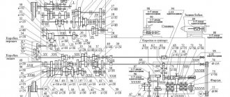
Kinematic diagram
The electrical circuit consists of two asynchronous motors powered by a 380 V industrial AC network. It is possible to power a step-down transformer from a 220 V network.
Provides 12 V to power the lighting lamp and 110 V to power the circuit controls. These switch buttons, starters and overcurrent protection elements (thermal relays). Electrical equipment is the main weak point of the machine. Requires constant monitoring.
Electrical diagram
Variable speed drive
The variator consists of a two-stage gearbox and the variator itself. The main motor rotates the drive shaft through a gear coupling. There are two conical disks on the shaft. One is rigidly fixed, and the other is spring-loaded and can move along the axis.
These two discs form the drive pulley of the variator. The drive pulley uses a V-belt to rotate another pair of identical disks, forming the driven pulley. They are located on the driven shaft. It transmits rotation to the gears of the range switching box.
Headstock
The front (spindle headstock) is rigidly fixed to a massive frame. The spindle head housing contains:
- spindle - rotates in precision rolling bearings;
- overkill - a set of gears that allows you to expand the range of thread pitch by changing the gear ratio;
- lead screw drive with bit (controls change in feed direction);
- control mechanism;
- mechanism for supplying lubrication to bearings and gears.
Gearbox
The feed box and guitar change the gear ratio to cut threads with different pitches and obtain longitudinal and transverse feeds.
Caliper
The cross-type machine support consists of:
- lower slide – moves longitudinally along the frame guides;
- cross slide – moves in the transverse direction;
- rotary slide – fixed on the cross slide and set to the required angle according to the scale marked on the cross slide. Used for making cones;
- tool holder – rotatable to 4 positions with locking.
Apron
Designed to provide longitudinal and transverse feed of the caliper. Equipped with a mechanism for blocking the simultaneous activation of the lead screw and the lead shaft.
Purpose and classification of lathes
Lathes include a large group of machines designed primarily for processing workpieces in the form of bodies of revolution made of metals.
The main technological operations performed on lathes are turning cylindrical, conical, shaped, and end surfaces of workpieces rotating coaxially with the spindle axis, and thread cutting.
The functionality of lathes can be significantly expanded through the use of special devices on turning equipment that allow milling, drilling, grinding and some other types of processing.
The basis of the turning group consists of automatic and semi-automatic lathes, screw-cutting lathes, turret lathes, rotary lathes, and lobe lathes.
For external and internal surface treatment of single and small groups of workpieces, including thread cutting, various models of screw-cutting lathes are used.
Turret lathes are designed for processing small and large groups of complex-shaped workpieces made from rods or piece workpieces that require the use of a large number of tools.
Rotary lathes are used to process the surfaces of workpieces of various shapes, whose diameter is much greater than their length. They differ from other lathes in the vertical location of the axis of rotation of the faceplate, to which the workpiece is attached.
To process large-diameter workpieces (up to 5 m) used in the manufacture of parts in individual production, lathes are used.
Lathes are classified:
- by type of material being processed (steel, cast iron, non-ferrous metals, plastic, etc.);
- processing accuracy (classes N, P, B, A, C);
- type of production (single, small-scale, serial, large-scale, mass);
- weight of the machine (light, medium, large and heavy);
- the maximum diameter of the workpiece (D) of the workpiece or the height of the centers above the bed (100...5000 mm);
- the longest length of the workpiece L (125...24,000 mm).
Typically, light lathes include lathes with a maximum diameter of the workpiece D = 100...200 mm, medium - D = 260...500 mm, large - D = 630...1250 mm, heavy - D = 1600...5000 mm.
On medium-weight lathes in mechanical engineering and metalworking, 70...80% of the total volume of turning work is performed. They are used to perform semi-finishing and finishing machining of parts from workpieces and cutting threads. They have a fairly high level of automation. To expand their technological capabilities, they are equipped with various devices that facilitate the turner’s work and improve the quality of processing.
Lathes have sufficient power, high rigidity and a wide range of spindle speeds and tool feeds, which allows processing parts using advanced tools made of hard and super-hard materials.
Lightweight lathes are used in tool production, watch industry, instrument making, electrical industry, experimental and pilot production.
Large and heavy lathes are used for processing parts of heavy, power and transport engineering in the manufacture of nuclear reactors, turbine rotors, generators, traction motors of electric locomotives, etc. Machines of this type are less universal than medium-type machines and are mainly adapted for processing certain large details.
Lathes produced by machine tool factories in Russia have an alphanumeric designation. Decoding the alphanumeric designation of a lathe gives an idea of its main characteristics (type, dimensions of the workpiece being processed, processing accuracy, etc.).
Operating instructions, passport
Before starting work, it is necessary to check the oil level in the oil indicators. Apply the required amount of oil to all indicated lubrication points. Check the strainers for chips and dirt. If necessary, rinse in kerosene.
Pour coolant into a special container in the cabinet.
Conduct an external inspection of electrical equipment.
- Why get started:
- Set the spindle rotation speed.
- Set the feed amount.
- Start work.
After finishing, clean the machine from chips and dirt, clean the filters.
The lathe's passport can be downloaded for free from the link - Passport for the OT-5 screw-cutting lathe.
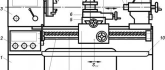
Design and control system features
- Bed.
- Support stand.
- Front grandma.
- Guitar.
- Transmission.
- Converting device.
- Switch.
- Frame.
- Lubrication unit.
- Apron.
- Caliper.
- Rear grandma.
- Cooling system.
- Fencing.
- Electrical equipment.
The electrical equipment of the machine is designed to be powered from a general network with a voltage of 220 V or 380 V. To illuminate the working area, a 12-volt voltage is required. The design of the device provides for the presence of two asynchronous electric motors. The electrical component of the machine is one of its most vulnerable points.
To avoid failure of the entire mechanism or its individual parts, it is necessary to regularly and carefully check the condition of the electrical equipment and replace faulty parts in a timely manner.
Video: lathe OT 5.