Manufacturer information
The direct developer of this machine is the Experimental Research Institute of Metal-Cutting Machine Tools.
The manufacturer, from 1932 to this day, is the Moscow Machine Tool Plant. The first designs were based on the Austrian analogue of the Unimat SL.
The primary version of the Station Wagon series had two guides. The 3M station wagon, unlike the first models, has been significantly improved and instead of two guides, it has one of a larger diameter, which is located in the middle of the frame.
Electrical equipment of the Universal-3M lathe. General information
According to the method of protection against electric shock, the electrical equipment of the machine belongs to class I, i.e. has working insulation, an element for grounding and a wire with a grounding conductor for connection to the power source and grounding.
The basic electrical diagram of the machine is shown in Fig. 14, the list of electrical equipment elements is in Table 4. Electrical equipment is located in a separate box (see Fig. 1, item 6). The box is closed with a lid. The cover is secured with two screws, one screw is located in the center of the cover under the rubber mat, the other secures the cover to the frame, ensuring the cover is grounded.
Tabletop machines of the Universal series
This is a separate category of machines that perform similar functions to large production analogues, but are adapted for processing small parts and operating from a household network.
They cost much less than their larger counterparts, and work in almost any conditions. The entire series has been in production for decades.
During this time, the machines have been modernized and have 3 generations. But at the same time, the entire series is in demand in modern conditions, since it is reliable and durable.
Description of the operation of the electrical circuit of the Universal-3M lathe
Electrical equipment is powered from a single-phase alternating current network with a voltage of 220 V and a frequency of 50 Hz.
Starting and stopping the electric motor is carried out using the KV relay (see Fig. 14), which is controlled by the SB2 (start) and SB1 (stop) buttons. When starting, the KV relay turns on and becomes self-powered, connecting the electric motor to the network with its contacts and providing zero protection, i.e. turning off the electric motor when there is no voltage in the network. The electric motor is protected from overload by the start-up relay A, which breaks the starting circuit, which turns off the KV relay. Restarting is possible only after 15-50 s, i.e. after the thermal protection elements of the start-up relay A return to their original position.
When starting the electric motor, its starting torque increases due to the connection of the starting capacitor C1 by the contacts of the start-protective relay A in parallel with the running capacitor C2. After the electric motor accelerates and the starting current decreases, capacitor C1 is turned off.
Reversing the electric motor is carried out using the switch SA, which, with the middle (vertical) position of the handle, ensures that the electric motor is turned off, i.e. it stops even when the KV relay is turned on. The handle should be left in a neutral position
Purpose and scope
The Universal -3M desktop machine is designed for processing medium and small workpieces in individual workshops. Such a mechanism can often be found in the offices of schools, institutes, and various colleges.
Perfect for home use. the main advantages are:
- small amount of noise;
- the ability to connect to a household electrical network;
- small dimensions of the machine;
- its versatility.
That is why the device is popular among various craftsmen. The machine is designed to perform the following operations:
- segment;
- boring holes of different diameters;
- drilling holes and chamfering;
- grooving and boring of various surfaces, cylindrical, conical.
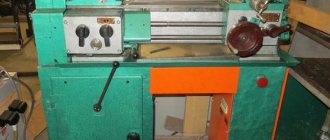
General view of the Universal-3M lathe
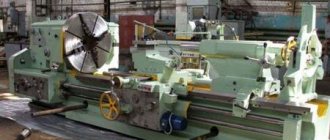
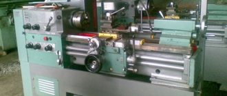
Photo of the Universal-3M lathe
Photo of the Universal-3M lathe
Photo of the Universal-3M lathe
End of the spindle of the Universal-3M lathe
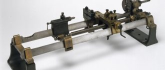
Photo of a guitar lathe Universal-3M
Photo of the Universal-3M lathe drive
Equipment Specifications
Compared to its predecessors, the Universal-3M lathe has improved characteristics and therefore significantly expanded capabilities compared to analogues. The accuracy class of the machine is N. According to GOST, this means that the machine is of normal accuracy and the permissible differences in linear motion are 10 microns.
Dimensions
Dimensions of turning equipment for the series in question:
- 675 x410x20 mm;
- weight – 60 kg.
When purchasing, it is important to choose the right work surface. It must fit these dimensions. It is necessary to make a calculation in order to correctly distribute the load and take into account where the greatest vibration will be.
The workpiece dimensions also have maximum allowable values depending on the location. When positioned above the bed, the largest possible diameter is 150 mm. If the workpiece is located on top, in relation to the bed, the diameter is no more than 9 cm.
The length of the workpiece structure when fixed in the centers is 250 mm. By drilling you can get a hole 6 mm in diameter.
The machine has 9 stages of rotation with speeds from 200 rpm to 3200 rpm.
Location of components
The components of this machine include:
- The drive itself.
- Fixed base.
- Spindle (front) headstock.
- Device for fastening the cutter (support).
- Stubborn grandma.
- Electrical equipment box.
The main unit of the machine is the bed and it is made by casting. All the main parts of the device are attached here.
Headstock
The headstock or spindle headstock has two supports to which the spindle is attached using bearings. This is a hollow steel structure with an internal hole. The spindle, through the operation of a pulley drive, receives 10 rotational speeds.
The front end of the spindle is equipped with an M20 thread. You can attach a lathe or driving chuck to it.
Caliper
The part has an installed cutter and moves along the longitudinal guides by 160 mm, and across by 55 mm. The support on this machine can only be moved manually, since the lead screw is not connected to the drive.
Description of the kinematic diagram of the Universal-3M screw-cutting lathe
Main drive chain
In this circuit, the spindle rotates from electric motor 3 through a V-belt drive (see Fig. 3). There are 9 operating spindle speeds.
Two stages (200 and 300 rpm) can be obtained if pulley 13, rigidly seated on the electric motor shaft, is connected by a belt to intermediate pulley 1, and that, in turn, along the stream “a” - with pulley 2, freely rotating relative to the electric motor shaft . From pulley 2 along one of two free streams - “b” or “c” - rotation is transmitted directly to pulley 9, rigidly connected to the spindle.
One stage (650 rpm) is obtained by transmitting rotation from pulley 13 directly to pulley 9, bypassing intermediate pulleys 1 and 2.
Two more stages (525 and 1000 rpm) can be obtained if a replacement pulley 12 is put on pulley 13 so that the end on which there are cams faces outward. From pulley 12, as in the first case, rotation is transmitted to intermediate pulley 1, and from it along stream “b” to pulley 2, which transmits rotation to pulley 9 along streams “a” or “c”.
The remaining four stages (1200, 1700, 2800 and 3200 rpm) are obtained if the electric motor shaft is connected to pulley 2 through pulley 12 using cams located at one of the ends of the latter. Now, along any of the four streams, rotation can be transferred to pulley 9.
Note: The 1200 rpm stage can be obtained without connecting the motor shaft to pulley 2.
Feed drive chain
The caliper is moved to the right and left using lead screw 14.
Rotation is transmitted to the lead screw directly from the spindle by a gear II rigidly attached to it.
Through gear 10, rotation is transmitted to gears 8 and A, then to the intermediate roller 5. There are two options for transmitting rotation to this roller: the first option (indicated by number I in the diagram) - through a block of gear wheels B-B and wheel D, and the second (indicated by number II in the diagram) - through gears B and C.
The first option is used for feeding during normal turning, the second - when cutting threads. A gear wheel 6 is rigidly connected to the roller 5. From this wheel to the wheel 7, mounted on the left end of the lead screw, rotation can be transmitted either through a pair of gear wheels 15 and 16 - and then the caliper will move to the left, or through the gear wheel 17, which will ensure moving the caliper to the right. All three wheels (15, 16 and 17) are mounted on the rotating device 4 (see D-D) and are in constant engagement with the gear wheel 6 (central). Thus, it is possible to move the caliper both to the right and to the left with the same direction of spindle rotation.
It is also possible to disable the support feed without stopping the spindle rotation. This is ensured by disengaging gears II and 10 using the same rotary device 4 and spring 18.
ATTENTION! To avoid breaking the gears of the feed drive chain, switching on and switching the direction of movement of the support should be done with the spindle not rotating.
The movement of the tailstock quill and the transverse movement of the caliper are carried out by handwheels through the corresponding screw pairs, as shown in the kinematic diagram.
Standard delivery set
When purchased, certain accessories and tools are included as standard. In some cases there may be additional components.
Accessories
The basic set includes the following accessories for the Universal series machine:
- three-jaw chuck complete with flange and ring;
- several return jaws and a key to the chuck;
- shank for a type of drill chuck;
- 2 thrust centers and one rotating;
- mandrel assembly for boring;
- collet F6 and F8;
- surface grinding device;
- milling and drilling device;
- vice;
- sharpening;
- mechanism for processing wooden structures;
- handyman;
- jigsaw;
- mechanism for working with a circular saw;
- screen;
- polyethylene oil can;
- cartridge casing.
Tools
Tools for the machine as standard:
- one open-end wrench;
- several socket wrenches;
- 7812-0373 40HFA N12x1 S=4;
- 7812-0374 40HFA N12x1 S=5;
- 7812-0375 40HFA N12x1 S=6;
- square key;
- chisel;
- for key S10x13 handle;
- several types of cutters: right through, boring, scoring, trimming, threaded external and internal;
- jigsaw and circular saw;
- twist drill;
- end mill with cylindrical shank Ø6.0 GOST 17025.
This is a complete set, which is enough to do all the basic work.
Milling and drilling device of the Universal-3M multifunctional machine
Milling and drilling device of the Universal-3M machine
The device (Fig. 4) is a rack 3, along the guides of which the table 4 moves. The movement is carried out by rotation of the handwheel I, rigidly connected to the lead screw 2. The workpiece is attached to the table with clamps 11 using pins 10, nuts 9, screws 8 and crackers 7, included in the T-shaped slots of the table. In order to set up the machine for milling or drilling work, it is necessary to secure the stand to the machine support using strips 6 and screws 5, as shown in Fig. 4.
The end mill or drill is secured in a collet clamp or in a special drill chuck 12 included in the delivery set.
The chuck 12 is connected to the spindle using a special shank 13, also included in the delivery set.
In addition to clamps, a vice can be used to secure the workpiece, which is fastened with screws using crackers to the table of the milling and drilling device. The fixed jaw of the vice has two prismatic grooves that allow you to conveniently fasten cylindrical parts.
Recommendations for use:
- for drilling work - drills 2300-0181 (GOST 10902-77)
- for milling work - end mills 2220-0037 (GOST 17025-71): Cutting speed no more than 15 m/min.
- Surface grinding device: Cup grinding wheel 18 (see Fig. 4) is mounted on mandrel 15 using screw 19 and washer 20. Gaskets 21 made of cardboard are placed under the wheel and washer. The mandrel with the circle mounted on it is screwed onto the front end of the machine spindle. Then a protective ring 17 is put on the casing 14, located above the spindle, and screws 16 with washers are fixed on it through grooves designed to adjust the position of the protective ring relative to the grinding wheel.
Design and operation
On the base there is an empty steel guide. This is the base for all other parts. The second base is a flat view of the guide of the same bed.
At the front, directly under the casing, there is a screw for longitudinal movement of the caliper. The bracket on which the machine drive electric motor is mounted is located on the left side of the headstock.
The bracket is covered with a casing, under which there are pulleys from the drive that rotate the spindle structure, as well as the feed drive structure itself.
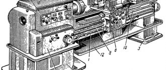
Location of controls for the Universal-3M lathe
Location of controls for the Universal-3M lathe
List of controls for the Universal-3M screw-cutting lathe
- feed movement control handle (turning on mechanical longitudinal feed of the caliper to the left, right and turning it off)
- main movement control handle (turning on forward rotation of the spindle, stopping and turning on reverse rotation)
- handwheel for transverse caliper movement
- toolholder movement handwheel
- quill clamp handle
- quill movement handwheel
- handwheel for longitudinal movement of the caliper
- button to turn off the power to the electrical equipment of the machine (red)
- power button for the electrical equipment of the machine (black)
Types of machine functions and its design
Universal 2 is a machine that can be quite easily transformed into a drilling or milling machine. Therefore , it can be used to cut, trim, cut threads with a cutter, bore holes, and sharpen simple or shaped surfaces. And after moving the main movement unit to a vertically mounted guide, drill, countersink and even mill, as well as grind the planes. Using optional accessories allows you to do the following:
- Sharpen cutting tools.
- Cut sheet material straight (with a circular saw).
- Plane a tree.
- Cut parts of any shape from sheet material (with a jigsaw).
The basis for fastening other parts and components of the machine is a cast iron frame.
The headstock of the product and two guides are attached to it. The main motor is located on the headstock of the product. The thrust head is installed on the guides. The rotation of the spindle by the main and only motor occurs through pulleys and a V-belt. And the feed mechanism, often called a guitar, is connected to the source of movement by a gear transmission.
Setting up the Universal machine and operating rules for the machine
When machining various materials (steel, cast iron, wood, plastic, etc.) and performing various types of processing (turning, sawing, drilling, grinding, etc.) depending on the material of the cutting tool (tool, high-speed steel or carbide) a certain cutting speed is required to ensure good surface quality and maintain the cutting properties of the tool. So, at a very high cutting speed, the cutting tool will quickly become dull, and at a very low speed, the processed surface will turn out torn or rough. To obtain an appropriate cutting speed, it is necessary that the spindle rotates at the appropriate number of revolutions n per minute, which can be determined using the following simple formula:
n = 320 V/D rpm
where V is the cutting speed in m/min;
D is the diameter of the workpiece or cutting tool (when the cutting tool rotates). The following cutting speeds are recommended:
- When turning steel and cast iron - 50-80 m/min with carbide cutters and 20-40 m/min with high-speed steel cutters.
- When turning wood - 80-150 m/min.
- When drilling - 15-30 m/min.
- When grinding - up to 20 m/sec.
- When milling - 15-30 m/min.
- When sharpening - up to 20 m/sec.
- When sawing wood - 300-500 m/min.
- When working with a jigsaw n = 280-710 rpm.