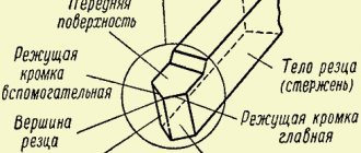
Formation of shaped surfaces
during turning, it occurs by rotating curvilinear generatrices around the axis of the product. Generators can also be combinations of lines of various profiles, creating a certain configuration of the part during rotation. There are several ways to manufacture and control the shape of products with shaped surfaces, including using:
- template;
- shaped tool;
- copier;
- a combination of these methods.
When using templates, the cutter feeds in both longitudinal and transverse directions. After cutting a certain layer thickness, a template is applied to the part to determine the size of the next layer to be cut.
The simplest way to obtain a shaped surface of a part is to use a cutter with a cutting edge that repeats a given curved generatrix.
The use of a copier makes it possible to obtain the most accurate part configuration. Sometimes in practice it is necessary to use a combination of all of the above methods - most often this concerns turning of elongated products using carbide and high-speed tools.
Modern machine tools provide high precision processing of workpieces, while the part must be securely fixed in the spindle or centers of the machine. In cases where the length of the workpiece significantly exceeds its diameter, additional supports are used - rests. In this way, the installation rigidity of the part can be significantly increased, which contributes to the processing accuracy.
The practical use of cutters with a curved configuration is limited by the width of their cutting part, which should not exceed 60 mm. The radius of cast iron and steel workpieces made of cast iron or steel is limited to 20 millimeters. In such cases, it is important to consider that the acting forces in the cutting zone must correspond to the overall rigidity of all components of the LED system.
If it is necessary to obtain a radius of the workpiece that exceeds 20 mm, pass-through cutters are used, the radius of curvature of which is less than the radius of curvature of the mating part, for example, a bearing.
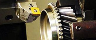
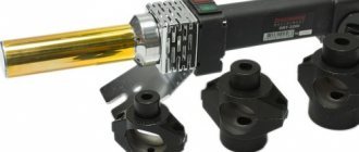
Shaped cutters:
a – whole; b – with mechanical fastening of the cutting part; in — disk
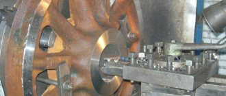
Machining with through cutters
In a single production, the requirements for manufacturing accuracy are low, so turning of shaped surfaces on machines is carried out manually, and the quality of workmanship is ensured due to the highly qualified workers. This is explained by the lack of automatic settings: the cutting process and the accuracy of the work are ensured by the performer, combining longitudinal and transverse movement of the cutter. To obtain practical processing skills, a finished part of a given shaped profile is installed in the machine spindle, along which the turner manually, using the handles of the machine support, moves the cutter so that its cutting part follows the contour of the product.
The turning process occurs in two positions. First, the handle blank is secured in the machine spindle by the cylindrical part A, and the shank is machined with a stepped shaped surface (B, C, D, E). Before this, markings along the length are applied to the workpiece. Then the part is turned over, secured to the machined stepped shank, and part G of the part is processed. First, the rough allowance is removed in several passes, then it is finished to the required size. Stopping the rotation of the spindle, a template is applied to the stationary workpiece several times, the maximum and minimum diameters of the handle are measured in order to bring its shape to the specified dimensions in several passes. In order to speed up the cutting process, the longitudinal movement is set to automatic mode, leaving manual control for the transverse slide.
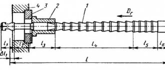
The sequence of processing the shaped surface of the handle with a cool cutter using longitudinal and transverse feeds:
a – finished part; b, c and d – semi-finished products for obtaining parts; A, B, C, D, E and G – processed surfaces
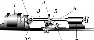
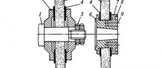
When working with a copier, a special device is used, complete with a copier 5, a rod 3 with a finger 4. The finger 4, sliding along the copier, ensures the movement of the rod connected to the support, moving it and the cutting tool mounted on it in accordance with the contour of the copier. It is recommended to move the caliper in the longitudinal direction in automatic mode, and disable the transverse feed. The tool, repeating the movement of the rod, forms the relief of the rotating workpiece.
Processing of shaped surfaces using a copy machine:
1 – cutter, 2 – handle, 3 – rod, 4 – finger, 5 – copier
Turning of workpiece surfaces
Turning
- technological process of cutting external, internal cylindrical, screw, conical and shaped, as well as flat end surfaces of bodies of rotation. Turning is carried out with turning tools on metal-cutting machines, both universal and special, including machines with computer numerical control (CNC). In addition, processing is performed on rotary and turret lathes, semi-automatic lathes, automatic machines and automatic lines.
The peculiarity of the technological processing process is that the cutting tool has one main blade. Throughout the entire cutting period, the cutter blade processes the workpiece under conditions of heavy loads and high temperatures.
When turning, there are two types of motion: rotational - around the axis of the workpiece, and translational - along its axis. Rotational movement
The workpiece is quantitatively characterized by the peripheral speed of the machined surface, called the cutting speed. Forward movement
along the workpiece axis imparted to the tool is the longitudinal feed motion. Both types of movement are carried out at a constant speed, and their combination gives the trajectory of the points of the cutter blade the appearance of a helical line. For each revolution of the workpiece, the blade of the turning cutter moves from position 1 to position 2 along its axis by the feed size s0 and removes one turn of the metal layer from it (Fig. 30.1). The width of the cut layer is determined by the cutting depth t.
The product of speed, feed and cutting depth is equal to the metal volume removal rate, which is a parameter for determining the efficiency of the cutting process. Cutting speed and feed
are the two most important parameters set by the operator in order to achieve optimal cutting conditions.
Depth of cut
is the thickness of the allowance to be removed, characterized by the distance between the machined and machined surfaces.
Typically, the cutting speed range is 0.005...3.5 m/s. The minimum feed value is 0.0125 mm/rev, and for very heavy cutting conditions - 2.5 mm/rev. The cutting depth can reach 25 mm or more.
A type of turning of workpieces is boring holes and processing end planes.
Boring is carried out according to the same principle as external turning. A feature of hole boring is a limited view of the cutting zone and low rigidity of the boring cutter. Under the influence of cutting forces, the tool bends and vibrates, which affects not only the size and roughness of the machined surface, but also the durability of the cutting tool.
To improve the accuracy of the holes made and the quality of the machined surfaces, instead of a cantilever-type boring cutter, it is preferable to use more rigid boring bars in which two cutters are fixed (Fig. 30.2). During the machining process, the boring machine imparts two types of motion to the mandrel: rotational - around its axis, and translational - along its axis. In this case, the peripheral rotation speed of the cutter tips is the cutting speed.
It is convenient to turn the end planes of workpieces using turning tools. In this case, machining can be carried out by moving the cutter both from the periphery to the center of rotation of the workpiece, and from the axis to the periphery.
Using shaped cutters
It is advisable to produce parts of short length using cutters with a working edge that exactly matches the given contour. A prerequisite for accurate execution of technical cutting parameters is that the front surface of the cutting tool must be located at the level of the center line of the lathe. The front surface is used to sharpen cutters for shaping, which is important to consider if there is a need to install them repeatedly. You should check that the cutter is installed perpendicular to the center line of the machine - this condition significantly affects the quality and cleanliness of the cut. Perpendicularity is checked using a square, one edge of which is located in the direction of the axis of the part, the other along one of the sides of the cutter. The cross-section of the cutter body can be round or rectangular - this makes it easier to process surfaces with complex terrain.
The installation location for prismatic radial shaped cutters is a horizontal turret or a transverse support. The line of the cutting edge of the shaped cutter must be level with the center of the part fixed in the spindle or in the centers of the part. The dimensions of the clearance angles α can be set by adjusting the position of the cutter in the holder, which is quite convenient at the stage of preparatory work.
In metalworking industries, preference is, as a rule, given to cutters with helical generatrices of cutting edges compared to cutters in which the cutting edges are made in the form of ring generatrices. This is explained by the fact that the surface processed by cutters with a helical generatrix is less rough, while at the same time the cutting process occurs much faster.
The high performance of cutters with a helical cutting edge is fully exploited when they are installed in a turret. To improve cutting quality, a uniform feed of no more than 0.05 mm/rev is used with a cutter width of 10...20 mm. Wider shaped cutters (width greater than 20 mm) are designed for feed rates up to 0.03 mm/rev.
Cutting modes
For tangential shaped models (in most cases prismatic), it is possible to process an object with several edges, on each side or several profile sections. In most cases, they are located at very different depth levels to ensure separate sequential processing. In order to process several objects according to a template, the tool is installed in one position and transverse and longitudinal feeds of the workpieces are performed. In this case, any point on the cutting edge begins and ends work at a wide variety of points, without continuing cutting beyond the boundaries of a given interval. Tangential cutters are also used with a rotary feed motion. Such models are suitable for thin workpieces and shallow profiles.
The best blood pressure monitor for the wrist in 2022 - TOP 8 rating of the best
Radial (radius) options (in most cases prismatic or round) are designed for rotational feed. The edge during processing with a shaped cutter of this type describes the surface to be worked radially. In this case, the feed movement for the edge intersects the axis of the object. This makes it possible to process with different depths and create curved shapes. Due to the large contact area, the equipment is subject to heavy loads. Moreover, when working with long objects of small cross-section, they may become deformed. In view of this, reduced modes are used.
Compared with radial models, they are suitable for working with stepped workpieces of lower rigidity due to the cutting of smaller sections and lower cutting forces.
For surfaces of rotation, the cutter performs a feed (usually translational, sometimes radial), and the workpiece performs a circular motion.
In addition to lathes, it is possible to use shaped cutters for planing, slotting and specialized for cylindrical objects. In these cases, radial design models with translational feed perpendicular to the axis of the part are used. For example, parts of gear shaping heads that work to work with cylindrical gears.
In the case of rotary feed, a tangential design is used. The edge of such models describes a surface of rotation, touching the object. In this case, any point on the edge at a certain moment removes a fragment of the workpiece and moves away from it.
The helical feed motion is used for workpieces of appropriate shape. In this case, the cutter does not cut at one level, but goes deeper after any pass. This is how threads are cut.
Characteristic
A shaped cutter is a tool that, as is clear from its sound, is designed to process shaped surfaces. The possibility of working on open planes and in the process of preparing grooves is provided. You can easily make even a very complex profile if you have good equipment and professional skills
Important: such models are designed primarily for workpieces that differ greatly in length and width
It is allowed to use both pointed and backed teeth. In the second option, their general profile must be identical to the profile features of the workpiece, and therefore it is necessary to reduce the rake angle to zero. If it deviates from this value, auxiliary modification will be required (of course, carried out by professionals according to technological protocols). The main check and, if necessary, rejection is carried out before starting work using a special template.
The production of shaped cutters is fully regulated according to GOST 9305, which was adopted in 1993. The standard covers both convex and concave hardware and hardware intended for rounding corners. Standard size is from 50 to 160 mm.
Other information:
- the size of the keyways cannot deviate from the values prescribed in GOST 9472;
- Technologists take additional information about the external dimensions of cutters from standard 29116;
- it is preferable to use high-speed steel, but the alloy 9ХС alloy is also officially approved for use;
- The grade of steel used must be indicated on the end of the device.
Information about shaped cutters
Cutters have an impressive variety of types - through cutters, boring cutters, groove cutters. Each type of cutter has its own purpose. Some are versatile and perform a large number of jobs. Others do one type of work, but do it perfectly. The shaped cutter was recognized as the most complex and non-standard tool.
It is used infrequently, but in the area of its use it is simply unrealistic to use any other type of cutters, since they simply cannot cope with the task. Therefore, choosing the right cutter can take a decent amount of time and effort. Another thing is that this is really worth doing, since a high-quality and appropriate cutter does the job quickly, simply, and without problems.
What has this type of chisel earned such laurels? Because it is used to process parts that have a complex, non-standard shape. Shaped-type cutters provide higher accuracy regarding the size and shape of the manufactured object - they reproduce the part with high accuracy. A shaped cutter is not used in every first enterprise - this cutter is more complex and original, most often this cutter is made to order, for a specific enterprise and for a specific thing that the cutter will produce until it breaks. Due to the specific nature of production, they are quite expensive and it is rational to use them only in large mass production.
Subtleties of the turning process
Separately, attention should be paid to turning shaped parts, when transverse and longitudinal feed is applied in parallel, carried out manually by the machine operator. This method of machining is used if it is necessary to produce a small batch of parts or the surface being processed is small in size. As for the first case, it is unprofitable to produce a conventional shaped cutter from an economic point of view, and to implement the second option, you may need a tool with non-standard dimensions, which causes difficulties in operation (for example, the formation of vibrations)
As for the first case, it is unprofitable to produce a conventional shaped cutter from an economic point of view, and to implement the second option, you may need a tool with non-standard dimensions, which causes difficulties in operation (for example, the formation of vibrations).
To remove the required layer of metal from the workpiece, either a finishing or a through cutter is used. The longitudinal slide moves to the left, and the transverse slide moves to the right and back. If it is necessary to process a surface characterized by small dimensions, then the longitudinal feed is realized by means of a support, which is installed in such a way that its guides are parallel to the center line of the equipment. Transverse feed in this case is carried out by the transverse slide of the caliper. The tool tip, regardless of the processing method, moves along a curve.
Processing parts with shaped surfaces is a rather complex task that requires certain skills and experience from the machine operator. Highly skilled turners prefer to use automatic longitudinal feed, while simultaneously performing cross feed manually. These processes can be fully automated using special copying devices. Their use is especially important when processing large batches of parts. Go to list of articles >>