Before we begin the practical connection of the starter, let us recall a useful theory: the contactor of the magnetic starter is turned on by a control pulse emanating from pressing the start button, which supplies voltage to the control coil. Keeping the contactor in the on state occurs according to the self-retaining principle - when an additional contact is connected in parallel with the start button, thereby supplying voltage to the coil, as a result of which there is no need to hold the start button pressed.
Disabling the magnetic starter in this case is possible only if the control coil circuit is broken, which makes it obvious that it is necessary to use a button with a break contact. Therefore, the starter control buttons, which are called push-button posts, have two pairs of contacts - normally open (open, normally closed, NO, NO) and normally closed (closed, normally closed, NC, NC)
This universalization of all the buttons of the push-button station was made in order to anticipate possible schemes for providing instant engine reverse. It is generally accepted to call the shutdown button the word: “ Stop ” and mark it in red. The turning button is often called the start button, start button, or is designated by the words “ Start ”, “ Forward ”, “ Back ”.
If the coil is designed to operate from 220 V, then the control circuit switches the neutral. If the operating voltage of the electromagnetic coil is 380 V, then a current flows in the control circuit, “removed” from the other supply terminal of the starter.
How to connect a magnetic starter. Connection diagram.
March 02, 2014 |
Section: Electrical Hello, dear readers of the site sesaga.ru. We continue to deal with the magnetic starter . In the first part of the article, we got acquainted with the device, purpose and operation of a magnetic starter, and today we will look at its electrical connection diagram .
But before assembling the circuit, let's make a small digression and get acquainted with one important element of the magnetic starter control circuit - the button
.
As you may have guessed, the “Start”, “Stop”, “Forward”, “Back” buttons remotely control the magnetic starter, and therefore the load that it switches. Control buttons are available in two types: with opening
and
a normally open
contact.
Problems with keyless car starting system
As noted earlier, the use of such a system is associated with a number of problems. Most of them cause inconvenience only in the absence of certain skills in using the presented system.
This may include:
- the need to manipulate the brake pedal;
- inconsistent operation of the system in the presence of the “autostart” function.
How to unlock the steering wheel
Another important problem that motorists who have equipped their cars with such a system often face is unlocking the steering wheel. Of course, as a last resort, you can resort to a barbaric method and get rid of the blockage using simple manipulations with a mounting tool and other tools.
On the subject: How to check the electronic gas pedal and repair it if necessary
You can solve this problem as follows:
- The first option involves making a duplicate of the ignition key, sawing off the top part, inserting the piece into the lock and turning the key to position 2, which means the steering wheel is unlocked.
- The second method involves completely dismantling the ignition switch; by the way, the start-stop button itself can be mounted in the resulting hole.
But it’s still much easier to use the services of professionals. The fact is that it is not always possible to unlock the steering wheel yourself, due to the characteristics of a particular car. Therefore, in this case, it is best to contact specialists.
Stop button.
The "Stop" button is easy to distinguish by its red color
blossom.
The button uses a break
(normally closed) contact through which the supply voltage passes to the starter control circuit.
In the initial position when the button is not pressed
, the moving contact of the button is pressed from below by a spring and
closes
two fixed contacts, connecting them to each other. And if the button is in an electrical circuit, then at that moment current flows through it. When it is necessary to open the circuit, the button is pressed, the moving contact moves away from the fixed contacts and the circuit opens.
When released, the button again returns to its original position by a spring that presses the movable contact, and it again closes both fixed contacts. The figure shows the button contacts in the pressed and not pressed position.
Installation Tips and Tricks
- Before assembling the circuit, you need to free the working area from the current and check that there is no voltage with a tester.
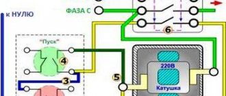
- Set the core voltage designation which is mentioned on it and not on the starter. It can be 220 or 380 volts. If it is 220 V, phase and zero go to the coil. Voltage marked 380 means different phases. This is an important aspect, because if connected incorrectly, the core may burn out or will not fully start the necessary contactors.
- Starter button (red) You need to take one red “Stop” button with closed contacts and one black or green button with the inscription “Start” with invariably open contacts.
- Please note that power contactors only force or stop the phases, and the zeros that come and go, conductors with grounding are always combined at the terminal block, bypassing the starter. To connect a 220 Volt core to the addition, 0 is taken from the terminal block into the design of the starter organization.
You will also need a useful device - an electrician's tester, which you can easily make yourself.
The article details several ways to update the BIOS on an Asus motherboard.
Now you can definitely choose the ideal laptop for work or study!
This article describes the benefits of SSD drives for applications and games. There is also a comparison between the advantages of this drive with its outdated counterpart.
Start button.
Typically, the Start button is painted black.
or
green
colors.
The button uses open
(normally open) contact, which, when closed, causes electric current to flow through the button.
The “Start” button is designed in the same way as the “Stop” button, and differs only in that in the initial position its moving contact does not close
fixed contacts - that is, it is always in
an open
state. On the left side of the figure you can see that the moving contact is not closed and is pressed upward by the spring.
When you press the button, the moving contact moves down and closes both fixed contacts. When the button is released, its movable contact, under the action of a spring, returns to its original upper position and the contacts open.
Application of reversing starters
The start-stop button can be connected via reversing starters with or without converters. If we consider the first option, then capacitors are used with semiconductor insulators. The winding itself is used at 15 V. The resistance value on it must be at least 30 Ohms.
The comparator for the switch is used for two outputs. The first contact closes in the first phase. The stabilizer must be in the open state. Some modifications are sold with filters. It is also worth noting that there are contactors with unijunction resistors.
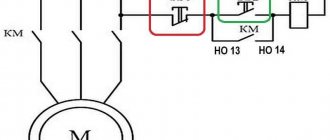
Magnetic starter connection diagrams.
The first, classic scheme, is intended for the usual start of an electric motor: the “Start” button is pressed - the engine turns on, the “Stop” button is pressed - the engine turns off. Moreover, instead of a motor, you can connect any load, for example, a powerful heating element.
For ease of understanding, the circuit is divided into two parts: power part
and
control circuits
.
Power section
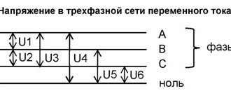
powered by three-phase alternating voltage 380V with phases “A” “B” “C”.
The power part includes: three-pole circuit breaker QF1
, three pairs of power contacts of the magnetic starter
1L1-2T1
,
3L2-4T2
,
5L3-6T3
and a three-phase asynchronous electric.
engine M.
_
Control circuit
receives power from phase “A”.
The control circuit diagram includes the SB1
“Stop” button, the
SB2
“Start” button, the magnetic starter coil
KM1
and its auxiliary contact
13NO-14NO
, connected
in parallel with
the “Start” button.
When turning on the QF1
phases “A”, “B”, “C” arrive at the upper contacts of the magnetic starter
1L1
,
3L2
,
5L3
and are on duty there.
Phase “A”, which supplies the control circuits, comes through the “Stop” button to contact No. 3
of the “Start” button, the auxiliary contact of the starter
13NO
and also remains on duty at these two contacts. The circuit is ready for use.
When you press the “Start” button, phase “A” hits the coil of the KM1
, the starter is triggered and all its contacts are closed.
Voltage appears at the lower power contacts 2T1
,
4T2
,
6T3
and from them is supplied to the electrical circuit. engine. The engine starts to rotate.
You can release the "Start" button and the engine will not turn off, since using the auxiliary contact of the starter 13NO-14NO
, connected
in parallel to
the “Start” button,
self-recovery
.
It turns out that after releasing the “Start” button, the phase continues to flow to the coil of the magnetic starter, but through its 13NO-14NO
. In the lower figure, the arrow shows the movement of phase “A”.
Where and why it is used
Electromagnetic starters and contactors are built into a power network that transports current; it can be direct or alternating voltage; the work is used on electromagnetic induction. The devices are equipped with a set of signal contacts, through which the connected devices are powered. Some perform an auxiliary function, while others perform a working function.
Electrical installations and electric motors are controlled by starters, but do not protect them in the event of a voltage drop, since the power contact opens, and the operation of the device to which the electromagnet is distributed is suspended and independent activation is excluded.
To put the equipment into operation, you need to use the “start” button. This ensures safety, since accidents may occur due to spontaneous activation.
The starter connection circuits may include relays with thermal action; they are designed to protect electric motors and other installations from long-term operation. There are single-pole and double-pole magnetic starters. They are triggered when exposed to a current overload of motors through which voltage passes.
Starter connection diagram
Switches are used to supply power to various electrical appliances. Depending on the power of the electrical installation, the contacts of the switches are designed: the higher the current (power consumption), the greater the mass and contact area of the metal. Accordingly, the clamping device (spring, steel plate) must provide greater pressing force. If the switch is manual (mechanical), its size will be too large and it will be inconvenient to use.
Such input devices have a number of disadvantages (in addition to dimensions):
- too much effort when turning on (off);
- contact groups are not designed for frequent switching: they wear out quickly;
- safety issues have not been resolved: too much time is wasted when emergency shutdown is necessary;
- “switches” must be placed near the work area (in close proximity to the electrical installation), this is not always convenient due to the same dimensions.
The only way out is to connect the motor (or other electrical appliance) through the starter.
Design features
Depending on the number of controlled electricity consumers, the posts can be two-button ("Start" and "Stop" pushers) and multi-button. In addition, when performing electrical and electrical work, single buttons are used, which the user can independently install on any control panel.
Push-button stations are mounted in a plastic or metal case that has mounting holes for installing the fittings in a place convenient for use. A separate group consists of push-button stations designed to control hoists (PKT series), beam cranes and overhead cranes with ground control.
The main functional element of the device that starts, stops or switches the modes of the electricity consumer is a push button - an electrical switching fixture with manual control.
Today, control panels use two types of pushers:
- With self-return, in which the button returns to its original state due to a return spring installed on the pusher on the bottom side.
- Pushers with position fixation (self-holding), which close the contact and hold it until pressed again.
The most common is a two-button starting valve, the design of which is shown in Fig. 2. The remote control consists of a housing 1 and a front panel 2, which are connected to each other by screws 3. The buttons are painted in different colors and control a pair of contacts located inside the housing.
In the free state of the “Start” button, its pair of contacts is open, while the “Stop” button, on the contrary, is closed. When you press the start button, its contacts close.
There are a huge number of switching schemes for various electrical systems and devices with just two buttons. However, most of them do not provide direct voltage supply to the consumer, but through the contacts of a magnetic starter, which are designed for high currents and voltages.
The pushers themselves have different shapes and colors, which in fittings produced in Russia are usually reflected in their symbol.
According to their shape, pushers are divided into:
By pusher color:
- Stop buttons are usually colored red (“R”) or yellow (“G”);
- “Start” pushers can be black (“B”), blue (“C”), green (“Z”) or white (“B”).
Advantages of implementing such a connection scheme
- The switch and control manipulator (button) can be separated. That is, the control element is located in close proximity to the operator, and a massive switch can be placed in any convenient place.
- It can be controlled using a foot drive (hands remain free). This allows for better control of the electrical installation and for holding the workpiece.
- The remote starter connection diagram allows you to place safety devices. For example, short circuit protection or thermal relays that are triggered by temperature overloads. In addition, this scheme makes it possible to implement mechanical protection: when the moving parts of the electrical installation move to a critical point, the limit switch is triggered and the magnetic starter opens.
- The remote location of the control elements allows the emergency button to be located in a convenient location, which increases operational safety.
- It is possible to install a single push-button station to control a large number of magnetic starters when electrical installations are located in different places and at great distances. The connection diagram through such a post involves the use of low-current control wiring, which saves money on the purchase of expensive power cables.
- To control one starter, you can install several push-button stations. In this case, control of the electrical installation from each post will be equivalent. That is, you can start the electric motor from one point and turn it off from another. Connection diagram for several push-button posts in the illustration:
- Magnetic contactors can be integrated into an electronic control system. In this case, commands to start and shut down electrical installations are given automatically, according to a given algorithm. It is impossible to organize such a system using mechanical (manual) switches.
Cost indicators
The cost of Russian push-button posts is quite low and depends primarily on the number of buttons, category of placement and climatic design. Devices in a metal case are slightly more expensive than analogues installed in a plastic case.
For example, the price of two-button devices “PKE-222-2” is in the range of 250.0...280.0 rubles. A similar device with a mushroom-shaped “Stop” button will cost a little more – 380.0 rubles.
The price of one-button posts does not exceed 150 rubles. The six-button telpher remote control “PKT-60” costs 300.0 rubles. A device with a similar number of buttons and electrical parameters, equipped with a key (“foolproof”), will cost 200.0 rubles more.
How to connect a 220V starter with a button
The most common switching scheme is a single-phase consumer with a push-button start. Moreover, the buttons should be spaced apart: “start” separately, “stop” separately. To understand how to connect a magnetic starter, let’s draw a combined diagram showing the parts:
In our case, we use a single-phase power source (220 V), separated control buttons, a protective thermal relay, and the magnetic starter itself. The consumer is a powerful electric motor.
- The neutral cable (N) is connected simultaneously to the electric motor and the control circuit contacts.
- The “stop” button (Kn2) is normally closed: when released, electric current flows through it.
- The phase line (F) is controlled by a thermal relay (TP) protective circuit and is connected to the input operating contacts of the starter (PM1).
- The starting electrical circuit from the phase is connected to the winding of the starter solenoid (PM) through closed (without overheating) contacts of the thermal relay (TP-1).
- In parallel with the normally open “start” button (Kn1), the contacts of the service circuit of the magnetic starter (PM4) are connected.
- When the start button is pressed, electric current flows through the contactor solenoid. The contacts (PM1) - power supply to the electric motor and (PM4) - power supply to the starter solenoid close. After releasing the “start” button, the control and power circuits remain closed, the circuit is in the “on” mode.
- When the line overheats, the thermal relay (TP) is triggered, the normally closed contacts (TP1-) break the solenoid circuit, the contactor opens, and the consumer is switched off. You can turn it on again after the thermostat has cooled down.
- To force the consumer to de-energize, just touch the “stop” button (Kn2), the solenoid power circuit will open, and the consumer’s power will stop.
This key connection scheme for a 220 V magnetic starter allows you to safely use powerful electrical installations and provides additional protection in case of current line overheating. For example, if the motor shaft stops under load.
A simplified diagram (without protective devices and thermal relays) in the illustration:
In this case, the solenoid (and, accordingly, the power contact groups) is controlled manually using two buttons.
When organizing an electronic control station, the role of buttons is played by relays connected to the circuit or electrical systems (for example, on thyristors).
As a bonus, consider connecting using an outlet with a timer. In this case, the switching circuit works without a “stop” button. That is, in the presence of control voltage (from the timer), the electrical installation operates.
What is the difference between starters and contactors?
The purpose of these types of devices is almost the same, but there is still a difference. The operating principle of these devices is also the same, since their operation is based on the operating principle of an electric magnet. They are designed to operate in DC circuits with voltages up to 440V, as well as in AC circuits with voltages up to 600 V. Both have:
- Working (power) contacts to control the operation of the load.
- Auxiliary (control) contacts that ensure the functioning of signaling devices.
It would seem that there is no difference, but it is there and quite significant. Starters are produced to operate at low currents up to 10A, but contactors are designed for switching electrical circuits with high currents, which amount to hundreds of amperes. In this regard, their design may differ due to the presence of arc chambers.
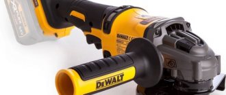
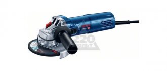
The appearance is not always so different, but it happens
In addition, starters are produced in housings made of durable plastic, but contactors do not have housings (in most cases), so their installation requires protected places, such as boxes, entry into which is not possible for unauthorized persons except maintenance personnel. In addition, contactors must be protected from moisture, dust and dirt.
Starters are mainly intended for turning on/off asynchronous 3-phase electric motors. In this regard, these devices are equipped with 3 pairs of working contacts, as well as auxiliary contacts that supply power to the starter in operating mode. Such functionality is quite universal, so starters are used to control the operation of various devices located at a considerable distance.
Since their operating principle is practically the same, starters are often called “small contactors”. This can mainly be found in price lists, although previously contactors and starters were clearly distinguished. As a rule, even electricians worked more with starters.
Types and classes of contactors
Contactors are designed for remote or automatic switching of power lines for high-power electrical appliances. These electrical products include panel-mounted devices, the power of which is practically unlimited, as well as modular devices for installation on a DIN rail. In the latter case, the permissible current, as a rule, is no more than 63 amperes. Small-sized (non-modular) DIN rail-mount contactors are rated for currents up to 100 A and are actually panel-mount products for a fairly simple reason: their dimensions do not allow the panel faceplate to be correctly installed in place.
Left: 63A DIN rail modular contactor. Right: Panel mount contactor.
The generally accepted classification of magnetic contactors implies their division into values corresponding to the standard size and permissible current load. Thus, modular devices are limited to the 4th value, but there are 7 values in total; with maximum dimensions, the contact group is designed for a current of up to 250 A.
Outside the scope of the general classification are contactors capable of switching circuits with a current of 1000 A and above, but such devices have a narrow industry application and we will not consider them.
Individual contactor models may have differences in electrical insulation class and permissible switching voltage. There is also a difference in the operating voltage for which the retractor electromagnet coil is designed. Additional differences include:
- number of switched poles of the power contact group (from 1 to 4);
- response time (from 0.01 to 1 s);
- type and efficiency of arc extinguishing devices for different degrees of load inductance;
- permissible number of switching cycles per hour;
- noise and vibration levels;
- the presence and number of additional low-current contacts.
The device of a three-pole contactor with normally open contacts: 1 - coil; 2 - fixed magnetic circuit (core); 3 - movable core; 4 - fixed contacts; 5 — dielectric holder of movable contacts; 6 - moving contacts
The concepts of contactor and starter reflect different essences. Thus, the name contactor implies a monoblock device with only the set of functions provided for by the design. A starter is a set of devices combined within one control assembly. It may include several contactors, as well as additional attachments, protective devices, controls and a housing with a certain degree of dust and moisture protection. Starters, as a rule, are designed to control the operation of asynchronous electric motors.
Combination motor starter
Principle of operation
When voltage is applied to the electromagnet coil, the moving part of the device is set in motion under the influence of electromagnetic forces and is attracted to the stationary part. In this case, the power contacts are closed and voltage is supplied to the actuator. And also at the same time there is movement of block contacts, which can be making or breaking.
How to connect a three-phase motor via a magnetic starter
Power supply 380 V (three phases) is carried out in the same way, only there will be more power wires.
The contactor includes not one, but three phase lines. In this case, the control button is connected according to a similar circuit (as in the single-phase case).
The illustration shows a starter with a 380 V solenoid control coil. The control circuit is switched between any two phases. For safety, there is a thermal relay, the sensors of which can be located on one or several phase wires.
How to connect a 3-phase contactor with a 220 V starter winding? The circuit is similar, only the control circuit is switched between any of the phases and the neutral wire. The thermal relay works just as accurately, since its mechanism is tied to the temperature of the power cables.
Connection to a three-phase network via a contactor with a 220 V coil
Through a standard magnetic starter operating from 220 V, three-phase power can be connected. This magnetic starter connection diagram is used with asynchronous motors. There are no differences in the control circuit. One of the phases and “zero” are connected to contacts A1 and A2. The phase wire goes through the “start” and “stop” buttons, and a jumper is also placed on NO13 and NO14.
How to connect a 380V induction motor via a contactor with a 220V coil
The differences in the power circuit are minor. All three phases are supplied to L1, L2, L3, and a three-phase load is connected to outputs T1, T2, T3. In the case of a motor, a thermal relay (P) is often added to the circuit, which will prevent the motor from overheating. The thermal relay is placed in front of the electric motor. It controls the temperature of two phases (placed on the most loaded phases, the third), opening the power circuit when critical temperatures are reached. This magnetic starter connection diagram is used often and has been tested many times. See the following video for assembly procedure.
How to change the direction of rotation of a motor using a starter
Three-phase electric motors make it possible to set the direction of rotation. There are many schemes for single-phase 220 V power supply. And for three-phase (380 V) switching, there is a connection diagram for a reversible magnetic starter.
The device consists of two independent circuits, with separate control of each group of contacts (pm1 and pm2). Each solenoid winding (PM1 and PM2) is controlled by its own button. In this case, there is only one stop key; it simply breaks the control circuit (as in a single starter). The connection of the input and output contacts of the second group is made with the so-called “phase shift”. In this case, the windings of the electric motor create torque on the shaft in the opposite direction.
The thermal relay is unchanged: their task is to open the starter in case of overload.
There is one feature:
To prevent a short circuit between phases, groups of contacts (pm1 and pm2) should not be closed at the same time. Therefore, they are mechanically placed on one rod, and purely physically cannot be connected to the power bus together. If you try to press the second button (while the first one is working), the power supply to the consumer will turn off.
How the Start/Stop button works
Before starting all the work, it is important to understand the fundamental features of the device and understand the intricacies of its operation.
Without going into details, the procedure for activating this system itself consists of sequentially performing the following steps:
- disabling the alarm;
- pressing the brake pedal;
- pressing the treasured button.
The last action involves briefly starting the car starter. In order to turn off the car, you should press the same brake pedal all the way and press the magic button.
How to connect a magnetic starter via a button
The times when switching of three-phase asynchronous electric motors was carried out using manual switches are long gone. They were replaced by more advanced devices - magnetic starters.
This device allows you to remotely control the working processes of electrical equipment, ensuring a high level of electrical safety.
Recently, starters are increasingly used for remote control of powerful consumers of electricity: compressor units, pumps, air conditioning, ventilation systems, etc. One of the new applications is implementation in lighting and alarm control systems.
Structurally, modern magnetic starters consist of two parts:
- A permanently fixed lower part and a contact block that moves along skids.
- There are 4 contacts on the top of the device - 2 normally closed and 2 normally open.
The basis of any magnetic starter is a magnetic circuit and an inductor.
When voltage is turned on to the coil of the magnetic starter, the armature is instantly attracted to the core, thereby closing the power and auxiliary contacts, which send a signal to the control system to start or turn off the device.
By means of a return spring, when the voltage is removed from the coil, all contacts open (return to their original position). Starters can be used on both direct and alternating voltage. The most important thing is that it does not exceed the parameters recommended by the manufacturer.
The classic version of connecting a magnetic starter involves the use of two control buttons: the “Start” button and the “Stop” button, which are sequentially connected to the phase supply circuit to the magnetic coil connector. They can be placed either in separate housings or in a common housing (the so-called push-button post or push-button station).
This is what the simplest connection diagram looks like:
As can be seen from the connection diagram of the magnetic starter buttons, when the “Start” button is closed (pressed), the circuit is closed, as a result of which current begins to flow through the coil, drawing in the core and thereby closing the power and auxiliary contacts.
To stop the controlled device or equipment, simply press the “Stop” button, which will open the circuit. Both buttons have a similar structure and differ only in that in the initial position the Start button is always in the open state.
Connecting a magnetic starter with Start and Stop control buttons with your own hands is quite simple. Now we'll tell you how to do this.
VIDEO REVIEW ” alt=””>
Operating principle and device
It is very important to understand what the principle of operation of starters is based on, as well as how they are designed, in order to better understand the connection diagram.
The basis of the design is an electric magnet, which, in turn, consists of a moving and a fixed part. The magnetic core is distinguished by its “W”-shaped shape, while it is, as it were, cut in the middle and installed with “legs” opposite each other.
Magnetic starter device
As a rule, the lower part is stationary and securely attached to the body. The upper part is movable and mounted on springs, which automatically turn off the starter if there is no operating voltage on the coil. It should be noted that starters are available for different operating voltages, from 12 to 380 volts. The coils are easy to change, so the starters are quite repairable and the weakest link is the coil. In addition, the starter also has moving and fixed contacts, both power and control. The moving contacts are located on the moving part of the magnetic starter.
When the coil is de-energized, the moving contacts are in an open state due to the action of the spring. When the “Start” button is pressed, voltage appears on the coil. As a result, the moving part of the core is attracted, and with it the moving contacts. By connecting to the fixed contacts, an electrical circuit is formed, as a result of which operating voltage appears on the control device (electric motor): the engine starts. This can be seen in the picture below.
This is what it looks like disassembled
When the “Stop” button is pressed, the voltage on the coil disappears and the upper, moving part, due to the action of the spring, returns to its original state. The contacts open, the electrical circuit disappears, as does the voltage on the electric motor: the electric motor stops. The electromagnet is triggered by both direct and alternating voltage, the main thing is that the coil is designed for the operating voltage.
There are starters with normally closed and normally open contacts, with the latter being the most common and most in demand.
⑤ Car engine start button, ignition start switch
Rating: 4.7 Price: 256.03 rub.
Go to store Compact and programmable start-stop device with LED lighting is used to quickly start the engine. It is made of waterproof stainless steel, so it works even in wet conditions. Installing the button does not require the help of a specialist - just insert the housing into the connector on the front panel of the car. There are 2 colors available to choose from – silver and black.
Advantages:
- has a backlight;
- made of metal;
- waterproof.
Flaws:
- non-latching button - closed while pressed.
Buy on AliExpress.com