Modern types of welding open up many possibilities for the master, allowing professionals and amateurs to realize their ideas. Using argon arc welding, you can join dissimilar metals, and using a budget inverter, you can weld a fence in your dacha. But sometimes welding equipment and components for them are not enough for full-fledged work; it is important to learn how to make and understand welding drawings. In them you can find out all the comprehensive information about the metal that needs to be welded, its thickness, characteristics and locations of future joints.
A drawing is a full-fledged document issued for one specific part or an entire metal structure. It contains all the information a welder might need. Reading welding blueprints proficiently is a must-have skill for any welder looking to build a career in the profession. In our article you will learn what is needed to decipher seams in drawings and what signs are used for this, we will also give several examples.
Types of seams and their interpretation
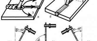
GOST standards for manual arc welding and gas welding distinguish different types of welds and their interpretation. Types of welded joints are designated by letters for easier recording and saving space. There are a butt seam (denoted by the letter “C”), an end seam (also the letter “C”), an overlap (“H”), a T-weld (“T”) and a corner seam (“U”). Let's take a closer look at each type of connection.
A butt welded joint is made at adjacent ends, and the parts to be welded are in the same plane. This type of weld is the strongest and most durable; it is widely used when welding particularly critical metal structures. Before welding, it is necessary to carefully prepare the metal surface and make sure that all parts will be welded in accordance with the drawing.
The end seam, as the name suggests, is formed along the ends of the parts. The side surfaces of the parts are securely connected to each other. The end weld is often used when welding thin metals.
The overlap seam is less demanding on the quality of work than the previous ones. But at the same time, it does not have such good strength characteristics and tolerates loads less well. To make an overlap seam, place the parts parallel, but with a slight offset to the side and partially overlapping each other.
The T-welded connection is one of the toughest and most durable, but does not withstand bending loads well. To make a T-seam, place one part horizontally, the second vertically and weld with the first end facing the surface.
The fillet weld is not used as often as other types of joints. This seam is relatively reliable and durable. One part relative to another can be turned end-to-end and positioned at different angles, depending on the drawing.
All welded joints, regardless of their type, can be single-sided (or as they are called “SS”; this abbreviation is used in drawings around the world) or double-sided (abbreviated “BS”). Single-sided seams are obtained by welding on one side of the part, and double-sided seams are obtained by welding on both sides.
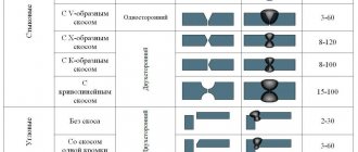
If you need to fusion weld parts, you will need to cut the edges. There are many forms of edge separation; they are characterized by different angles, gap sizes, and so on. The choice of cutting shape depends on the thickness of the metal and the welding method. We have provided some examples of the edge section in the image. You can use any one like in the picture below.
MOUNTING SEAM is... What is MOUNTING SEAM?
- An assembly seam is an element of an abutment assembly, which is a combination of various insulating materials that fill the installation gap and have specified characteristics. [GOST 30971–2012] Term heading: Window and door blocks... ... Encyclopedia of terms, definitions and explanations of building materials
- Assembly seam - Assembly seam: an element of the abutment assembly, which is a combination of various insulating materials intended to fill the installation gap, and having specified characteristics... Source: GOST R 52749 2007. Assembly seams... ... Official terminology
- Assembly seam - 78. Assembly seam A weld performed during installation of a structure Source: GOST 2601 84: Welding of metals. Terms and definitions of basic concepts original document... Dictionary-reference book of terms of normative and technical documentation
- Forceful operational impact on the assembly seam is the impact arising from the mutual movements of the window frame (frame) and the wall opening when linear dimensions change due to temperature, humidity and other influences, as well as during shrinkage of buildings. Source: GOST 30971 2002: Assembly seams ... Dictionary of terms of normative and technical documentation
- Operational force impact on the installation seam is the impact on the installation seam resulting from deformations of the wall opening and frame of the window unit due to changes in temperature, humidity conditions and wind loads during operation. [GOST 30971–2012] Category... ... Encyclopedia of terms, definitions and explanations of building materials
- Forceful operational impact on the assembly seam is the impact arising from the mutual movements of the window frame (frame) and the wall opening when the linear dimensions change due to temperature, humidity and other influences, as well as during shrinkage of buildings... Source: GOST 30971 2002.... ... Official terminology
- STO 75298253-009-2008: Window assembly joints. Technical specifications - Terminology STO 75298253 009 2008: Window assembly joints. Specifications: 3.3 lateral installation gap: The installation gap between the end surface of the window frame and the adjacent surface of the window opening. Definitions of the term from different... ... Dictionary-reference book of terms of normative and technical documentation
- GOST R 52749-2007: Window installation joints with vapor-permeable self-expanding tapes. Technical specifications - Terminology GOST R 52749 2007: Window installation joints with vapor-permeable self-expanding tapes. Technical specifications original document: 3.3 lateral mounting gap: Mounting gap between the end surface of the window frame and the adjacent one... ... Dictionary of terms of normative and technical documentation
- node - 04/01/14 node (computing networks) (2): An object that is connected or connected to one or more other objects. Note In a network topology or abstract layout, nodes are points on a diagram. In... ... Dictionary-reference book of terms of normative and technical documentation
- An abutment unit is a structural system, generally consisting of an SPK box, an assembly seam, a fastening system, a part of the enclosing structure, limited by the area of distribution of thermal inhomogeneity on its inner surface near the opening... Dictionary-reference book of terms for normative and technical documentation
dic.academic.ru
Illustration of welds in the drawing
Now let's move on to the conventional images and signs that characterize the seams in the drawings. Welded joints can be visible or invisible. If the seam is invisible, it is shown as a dashed line. If visible, use a solid line. An invisible seam is a seam that is located on the back side of a part, and a visible seam is a seam on the front surface. If the seam is one-sided and the welding is done with the seam facing up, then such a connection is also called a facial connection. If the seam is double-sided, then the connection that was made first is considered the front one. If the edges are symmetrical, then either side can be called the front side.
The one-way arrow shows where the seam line is. On the arrow itself there may be a special “shelf” where an auxiliary sign or letter designating a seam is indicated. Where should the symbols be located - under the “shelf” or above it? It also depends on the type of seam. If the seam is invisible, then under the shelf, and accordingly above it, if visible.
Non-standard cases
How is a weld seam indicated on the drawing if its dimensions do not fit within the GOST standards? In such a situation, the dimensions of all its elements should be included in the design documentation.
Then the performer, in the process of directly solving the problem, will be able to achieve the desired quality of the result, even taking into account the effect of residual stresses. The latter appear due to shortening deformation (which occurs due to uneven heating of surfaces) and are distributed depending on the selected mode, geometry and other factors. The thickness of the workpieces also cannot be discounted, because it can provoke plane or volumetric stresses.
Auxiliary signs
In addition to arrows and letters, auxiliary symbols can be used to indicate welds. Below you can see the standard structure of the symbol, its “skeleton”, on which “muscles” should then appear in the form of letters or other signs.
Auxiliary characters include alphanumeric combinations that contain information about the type of seam and type of connection. This sounds pretty confusing, but here's a quick example: We have the designation C1 and it stands for "single-sided butt weld." C is a letter indicating the type of seam, and 1 is a number indicating the side of welding. Double-sided welding is indicated by the number 2.
Below you can see symbols of seams and joints for some welding methods.
Welding methods also have their own symbol. They are also marked with a letter, this is indicated in regulatory documents. Based on the standards, the welding process indicated on the assembly drawing is carried out.
Below you can see the main welding methods and their designations:
- Automatic submerged arc welding, without the use of flux pads and pads during operation (indicated by the letter “A”).
- Automatic submerged arc welding using a flux pad (“AF”).
- Gas shielded welding using tungsten rods and no wire (“IN”).
- Welding in a shielding gas environment using tungsten rods and using wire (INp).
- Gas shielded welding using consumable rods (“IP”).
- Welding with consumable rods in a carbon dioxide environment (“WW”).
General information about welding
In modern mechanical engineering, parts connections made by welding are widely used.
Welding successfully replaces forgings, castings, and riveted joints, simplifying the manufacturing technology of parts and assemblies, reducing the labor intensity and cost of manufacturing the product, and also reducing its weight. Depending on the processes occurring during welding, a distinction is made between fusion welding and pressure welding.
Fusion welding is characterized by the fact that the surfaces of the edges of the parts being welded melt, mix together and, upon cooling, form a strong weld of a permanent connection. This type of welding includes gas and electric arc welding.
In gas welding, a flammable gas (for example, acetylene) burns in atmospheric oxygen to create a flame used for melting. A filler rod is introduced into the melting zone, as a result of which a weld is formed. Gas welding is used for welding both metals and plastics (polymers).
In electric arc welding, the heat source is an electric arc that occurs between the edges of the parts being welded and the electrode. Arc welding can be carried out with non-consumable (carbon or tungsten) electrodes or consumable electrodes.
In the case of using non-consumable electrodes, a filler rod is introduced into the zone of the emerging arc, which melts and forms a weld. Arc welding with consumable electrodes does not require the introduction of filler metal - the weld is formed as a result of melting of the electrode itself. Electric arc welding is used only for welding metals and their alloys.
Pressure welding is carried out with joint plastic deformation of preheated surfaces of the parts being welded. Deformation occurs due to the influence of an external force, pressing the surface areas of the parts being welded to each other. Pressure welding is carried out, as a rule, by one of the types of resistance electric welding: spot, seam - roller, etc.
In addition to the methods mentioned in modern mechanical engineering, other methods of welding parts are used (electroslag, inert gas, ultrasonic, laser, induction, etc.).
According to the method of mechanization of the technological process, manual, mechanized (semi-automatic) and automatic welding are distinguished.
To explain welding methods and parameters of welded joints in drawings, ESKD standards establish appropriate symbols.
Examples of symbols
To make it clearer for you and you can quickly understand all the notations, we will give several simple and illustrative examples. So, let's begin.
Example No. 1
In the picture above you see a butt seam in which one edge has a curved bevel. The connection itself is double-sided, made by manual arc welding. There is no gain on either side. On the front side the seam roughness is Rz 20 µm, and on the back side it is Rz 80 µm.
Example No. 2
Here you can see that the seam is corner and double-sided, it has no bevels or edges. This connection is made by automatic welding and using flux.
Example No. 3
Here we have a butt seam again, but without bevels or edges. The connection is one-sided, with a lining. The seam is made using heated gas and welding wire.
Example No. 4
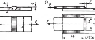
In the fourth example, the seam is a T-joint and has no bevels or edges. It is intermittent and performed using a bilateral method. The seam seems to be in a checkerboard pattern. The work was performed using RDS in a gas environment and using a non-consumable metal rod. The leg of the seam is 6 millimeters, and the length of the seam is 50 millimeters, in increments of 100 millimeters (indicated by the letter “Z”). t w is the length of the seam, and t pr is the length of the step of the intermittent connection.
Example No. 5
In our last example, the seam is overlapped and has no bevels or edges. It is also single-sided and is performed by manual gas-shielded arc welding using a consumable rod. The welded connection is made along an open line. The leg of the seam is 5 millimeters.