Home / Devices
Back
Reading time: 3 min
0
2883
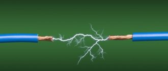
How to choose quality equipment? How not to make mistakes when buying? These and other questions plague every welder who knows about the difficulty of choosing a welding machine. We will talk about them in this article.
There are 2 types of modern welding mechanisms:
- AC units (transformers for welding);
- Direct current mechanisms (rectifiers, inverters).
The former are used much less frequently today. Although a quarter of a century ago such devices were at the peak of their popularity. This was due to the fact that there was simply no alternative.
- Relevance of the issue
- What's really going on?
- Welding arc: what is it?
- Why are changes needed?
- How to remake a mechanism at home
- Let's sum it up
Relevance of the issue
The main question for welders is considered to be: what current should the machine have in order for it to work for a long time and efficiently - unstable or static? It used to be much easier, because all the devices worked during breaks.
There was no difficult choice that arose literally 25 years ago. Today it is extremely difficult for an ordinary master to determine what will work better - inverters, transformers or rectifiers. It is worth dwelling on this issue in more detail.
What is alternating current? This is a standard electrical impulse that comes out of electrical outlets.
Old-style devices worked exactly on this principle: they connected a mechanism and received a couple of hundred Amps of welding current at the output. This was enough for successful work.
Today, technology is progressing, and devices are appearing that can change current from alternating to direct. But here's the catch: the inverter actually changes the AC to static. And this is not clear to everyone.
Our goal in this article is to tell you what both devices are. In addition, we will try to justify the importance of converting welding equipment from alternating current to direct current.
The design of a soldering iron operating on the pulse principle
A pulse soldering iron is relatively simple. It consists of:
- The tip is the working body, it is a V-shaped piece of copper wire with a thickness of 1 to 3 millimeters, fixed in a holder.
- Power source - supplies low voltage electric current to the tip.
- Pistol grip.
- Device power button.
- Network cable with plug.
- Light bulb or LED to illuminate the work area (optional, but very convenient)
The most complex component is the power source. It converts the mains voltage of 220 V 50 hertz into low voltage high frequency (20-40 kilohertz). The input circuit of the source is connected to the network cable through the power button, and the tip contacts are connected to the output circuit. There are various power supply circuits for pulsed soldering irons.
Pulse soldering iron device
The power source may be built into the handle. The transformer fixed in the housing is heavy and has noticeable dimensions. During prolonged operation, this will greatly tire the operator. In some embodiments, the power source is designed as a separate unit. This increases the safety and ease of use of the device. The device's power button is built into the handle.
The main design differences from a conventional soldering iron:
- Availability of power supply.
- Availability of a power button.
- No heating element.
- There is no need for a stand - the temperature of the soldering iron rises only during soldering, after releasing the button it very quickly cools down to room temperature.
Specific designs of homemade pulse soldering irons may differ from each other depending on what devices formed their basis.
What's really going on?
Many welders were perplexed when new types of machines appeared on the market. Transformers turned out to be not as simple as their predecessors.
The reason for this was the characteristics of alternating current. Unstable arc burning led to crooked seams. This was especially true for the work of newcomers.
Among the disadvantages of such mechanisms were:
- Loud noise during operation;
- Inaccurate welding, metal spattering;
- Difficulty working with the device.
A completely logical question arises: “Isn’t it better to use old equipment that generates alternating current?” Many masters, both with great and little experience, think about this controversial issue.
Semi-automatic Sanych
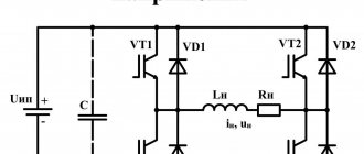
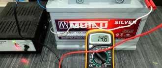
To make the transformer, Sanych used 4 cores from TS-720. The primary winding was wound with copper wire Ø 1.2 mm (number of turns 180+25+25+25+25), for the secondary winding I used an 8 mm 2 busbar (number of turns 35+35). The rectifier was assembled using a full-wave circuit. For the switch I chose a paired biscuit. I installed the diodes on the radiator so that they would not overheat during operation. The capacitor was placed in a device with a capacity of 30,000 microfarads. The filter choke was made on a core from TS-180. The power part is put into operation using a TKD511-DOD contactor. The power transformer is installed TS-40, rewound to a voltage of 15V. The roller of the broaching mechanism in this semi-automatic machine has a Ø 26 mm. It has a guide groove 1 mm deep and 0.5 mm wide. The regulator circuit operates at a voltage of 6V. It is sufficient to ensure optimal feeding of the welding wire.
How other craftsmen improved it, you can read messages on various forums dedicated to this issue and delve into the nuances of manufacturing.
Welding arc: what is it?
We said earlier that during operation the arc may burn unsteadily. The process is often noticeable to the naked eye: the welder does his job, and the arc deviates from the specified axis. As a result, the seam turns out uneven.
Beginners often make a lot of mistakes because they don’t know all the nuances. This is fraught with rapid extinction of the arc and incorrect operation.
Such moments suggest the uselessness of buying transformers for craftsmen without experience. But everything is somewhat different: if you learn to work with such a complex mechanism, then in the future you will not have difficulties with any other device.
If you are determined to abandon AC units, we will advise you on what to do. We will tell you what to do when you have already bought a transformer, but regretted it. Our goal is to tell you how to properly remake such a mechanism.
Wire feeding
Most often, such home-made semi-automatic machines provide the possibility of feeding welding wire Ø 0.8; 1.0; 1.2 and 1.6 mm. Its feeding speed must be adjusted. The feeding mechanism together with the welding torch can be purchased at a retail chain. If you wish and have the necessary parts, you can do it yourself. Savvy innovators use an electric motor from car wipers, 2 bearings, 2 plates and a Ø 25 mm roller for this. The roller is installed on the motor shaft. Bearings are attached to the plates. They press themselves against the roller. Compression is carried out using a spring. The wire passes along special guides between the bearings and the roller and is pulled.
All components of the mechanism are installed on a plate with a thickness of at least 8-10 mm, made of textolite, and the wire should come out in the place where the connector connecting to the welding sleeve is installed. A coil with the required Ø and grade of wire is also installed here.
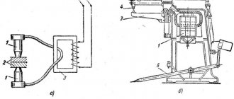
Pulling mechanism assembly
You can make a homemade burner with your own hands, using the figure below, where its components are shown clearly in disassembled form. Its purpose is to close the circuit and provide the supply of shielding gas and welding wire.
Homemade burner device
However, those who want to quickly produce a semi-automatic gun can buy a ready-made gun in a retail chain along with sleeves for supplying shielding gas and welding wire.
Why are changes needed?
As you already understand, it is impossible to say unequivocally which device is better - one operating on direct or alternating current. These are two different devices with their own advantages and disadvantages that should be taken into account when working.
Our advice is clear: buy universal equipment with two modifications.
There are such devices on the market. But they are quite expensive, so not everyone can buy them. Experienced craftsmen can safely take such a unit. Well, if you are a beginner and do not plan to carry out work too often, buy a transformer and remake it.
The latter works very smoothly. By modifying it a little, you will get a good device that can switch from alternating to direct current. This device will become a reliable assistant in any welding business.
How to make the most convenient transformer for welding: practical tips
Theoretically, you can use any model of transformer to power the welding machine. The main requirements for it:
- provide arc ignition voltage at idle speed;
- reliably withstand the load current during welding without overheating the insulation from prolonged operation;
- meet electrical safety requirements.
In practice, I have come across different designs of homemade or factory-made transformers. However, they all require electrical engineering calculations.
I have been using a simplified technique for a long time, which allows me to create fairly reliable transformer designs of medium accuracy class. This is quite enough for household purposes and power supplies for amateur radio devices.
It is described on my website in an article about making a transformer soldering iron Moment with your own hands. This is an average technology. It does not require clarification of the grades and characteristics of electrical steel. We usually don’t know them and cannot take them into account.
Features of core manufacturing
Craftsmen make magnetic wires from electrical steel of various profiles: rectangular, toroidal, double rectangular. They even wind coils of wire around the stators of burnt-out powerful asynchronous electric motors.
We had the opportunity to use decommissioned high-voltage equipment with dismantled current and voltage transformers. They took strips of electrical steel from them and made two donut rings out of them. The cross-sectional area of each was calculated to be 47.3 cm2.
They were insulated with varnished cloth and secured with cotton tape, forming a figure of a reclining figure eight.
They began to wind the wire on top of the reinforced insulating layer.
Secrets of the power winding device
The wire for any circuit must have good, durable insulation, designed to withstand long-term operation when heated. Otherwise, it will simply burn during welding. We proceeded from what was at hand.
We received a wire with varnish insulation, covered with a fabric sheath on top. Its diameter - 1.71 mm is small, but the metal is copper.
Since there was simply no other wire, they began to make the power winding out of it with two parallel lines: W1 and W'1 with the same number of turns - 210.
The core donuts were mounted tightly: this way they have smaller dimensions and weight. However, the flow area for the winding wire is also limited. Installation is difficult. Therefore, each power half-winding was separated into its own magnetic circuit rings.
In this way we:
- doubled the cross-section of the power winding wire;
- saved space inside the donuts to accommodate the power winding.
Wire alignment
You can get a tight winding only from a well-aligned core. When we removed the wire from the old transformer, it turned out to be bent.
We figured out the required length in our minds. Of course it wasn't enough. Each winding had to be made from two parts and spliced with a screw clamp directly on the donut.
The wire was stretched along its entire length on the street. We picked up the pliers. They clamped the opposite ends and pulled with force in different directions. The vein turned out to be well aligned. They twisted it into a ring with a diameter of about a meter.
Technology of winding wire on a torus
For the power winding, we used the rim or wheel winding method, when a large-diameter ring is made of wire and wound inside the torus by rotating one turn at a time.
The same principle is used when putting a winding ring on, for example, a key or keychain. After the wheel is inserted inside the donut, they begin to gradually unwind it, laying and fixing the wire.
This process was well demonstrated by Dmitry Volzhsky in his video “Winding the primary winding of toroidal transformers.”
This work is difficult, painstaking, and requires perseverance and attention. The wire must be laid tightly, counted, the process of filling the internal cavity must be monitored, and the number of turns wound must be recorded.
How to wind a power winding
For it, we found a copper wire of a suitable cross-section - 21 mm2. We estimated the length. It affects the number of turns, and the no-load voltage necessary for good ignition of the electric arc depends on them.
Typically reference books recommend 60-70 volts. One experienced welder told us that in our case 50 would be enough. We decided to check it, and if it wasn’t enough, then increase the winding further.
We made 48 turns with the middle terminal. In total, there were three ends on the donut:
- middle - for direct connection of the “plus” to the welding electrode;
- the outer ones - to the thyristors and after them to ground.
Since the donuts are fastened together and the power windings are already mounted on them along the edges of the rings, the winding of the power circuit was carried out using the “shuttle” method. The aligned wire was folded like a snake and pushed through the holes of the donuts for each turn.
The middle point was unsoldered using a screw connection and insulated with varnished cloth.
Let's sum it up
Every person involved in welding dreams of a universal mechanism that operates on direct and alternating current. But can a good device be inexpensive? The last condition is almost impossible to fulfill, because a ready-made mechanism costs a lot of money.
Of course, if you are an experienced welder who has a lot of orders every day, this is a good option. But what should a beginner do? After all, he is often not ready for big expenses.
In this case, golden hands and a couple of hours of free time will come to the rescue. Choose an inexpensive transformer, arm yourself with the support of an experienced friend - and you will be able to create a unique device.
The device will eventually be able to cook using direct current, and you will be satisfied with its performance. Even if you don't need the add-on, it's always convenient to have on hand. All parts for this design are easy to purchase. Or maybe they’re just collecting dust in your garage.
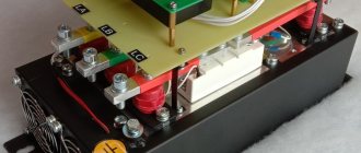
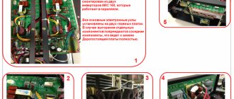
Sequential assembly of all parts
All elements of the welding unit must be located on a base made of metal or textolite strictly in their places.
According to the rules, the rectifier is adjacent to the transformer, and the inductor is located on the same board with the rectifier.
The current regulator is installed on the control panel. The frame itself for the structure of the unit is created from aluminum sheets; steel is also suitable for this.
You can also use a ready-made case, which previously protected the contents of the system unit of a computer or oscilloscope. The main thing is that it must be strong and solid.
A board with thyristors is placed at a great distance from the transformer. The rectifier is also not installed close to the transformer.
The reason for this arrangement is the strong heating of the transformer and inductor.
IMPORTANT TO KNOW: Welding sleeve for semi-automatic machine
Thyristors mounted on aluminum radiators remove heat from the inductor. They even cancel out the heat waves emanating from the wires.
An electrode holder is attached to the outer panel, and a wire with a plug is attached to the rear panel to connect the unit to a household network.
The video in our article demonstrates how to assemble a welding unit with your own hands.
Video:
Under no circumstances should the elements of the unit be fixed close to each other, as they must be subject to airflow.
It is necessary to make holes on the sides of the frame from where air will flow. This is also necessary for installing a cooling system.
If the welding unit is constantly in the same place, then it is unlikely that anything will happen to it.
The current regulator, or more precisely, its handle fixed on the outer wall, will be able to work for a long time.
But portable mini-inverters that are taken for field work may be subject to mechanical shocks. Basically, the body of the product suffers from this, but there is a risk of the throttle falling off.
The product is assembled - it’s time to check how it functions. When testing the operation of the welding unit, temporary wires should not be used.
You need to check the product with standard contact cables.
During the very first connection to the network, look at the current regulator. It is important to ensure that there are no unfixed parts left.
If the unit is in good working order and free from defects, then you can start welding in various modes.
Why remake the device?
Now you know that the question “So which current is better: alternating or constant?” has no answer. Devices on a break and devices on a permanent basis are two different phenomena with their own advantages and disadvantages. And ideally, it is better to have in your arsenal universal equipment that can cook with both direct and alternating current.
There are such devices on sale, but they are incomparably expensive. If you are a professional, then it makes sense to buy such a device. But if you are an amateur and cook a couple of times a year at your dacha or in the garage, then it is better to purchase a transformer device and modify it a little. A transformer operating on alternating current can be equipped with the ability to switch to direct current. This way you will get an inexpensive universal device, which will also be powerful and reliable.
Feeder
The electrode wire must be fed continuously and evenly - then the welding will be of high quality. The feed speed must be adjusted. There are three options for making the device:
- Buy a fully assembled mechanism. Expensive, but fast.
- Buy feed reels only.
- Do it all yourself.
If the third option is chosen, you will need:
- two bearings, guide roller, tension spring;
- motor for feeding wire - a motor from windshield wipers will do;
- metal plate for fastening the mechanism.
One pressure bearing - it should be adjustable, the second serves as a support for the roller. Manufacturing principle:
- holes are made on the plate for the motor shaft and for mounting bearings;
- the motor is fixed behind the plate;
- a guide roller is put on the shaft;
- bearings are fixed at the top and bottom;
It is best to place the bearings on metal strips - one edge is bolted to the main plate, and a spring with an adjusting bolt is connected to the other.
The completed mechanism is placed in the housing so that the rollers are located in line with the burner connector, i.e., so that the wire does not break. A rigid tube must be installed in front of the rollers to align the wire.
Implementation of the electrical part
For this you will need:
- two automotive relays;
- diode;
- PWM regulator for the engine;
- capacitor with transistor;
- idle solenoid valve - for supplying gas to the burner. Any VAZ model will do, for example from a V8;
- wires.
The wire and gas supply control circuit is quite simple and is implemented as follows:
- when you press the button on the burner, relay No. 1 and relay No. 2 are activated;
- relay No. 1 turns on the gas supply valve;
- relay No. 2 works in tandem with a capacitor and turns on the wire feed with a delay;
- wire pulling is done with an additional button, bypassing the gas supply relay;
- To remove self-induction from the solenoid valve, a diode is connected to it.
- It is necessary to provide for connecting the burner to the power cable from the inverter. To do this, next to the Euro connector, you can install a quick-release connector and connect it to the burner.
The semi-automatic device has the following operating sequence:
- The gas supply is turned on.
- The wire feed starts with a slight delay.
This sequence is necessary so that the wire immediately enters the protective environment. If you make a semi-automatic machine without delay, the wire will stick. To implement it, you will need a capacitor and a transistor through which the motor control relay is connected. Operating principle:
- voltage is applied to the capacitor;
- it is charging;
- current is supplied to the transistor;
- the relay turns on.
The capacitance of the capacitor must be selected so that the delay is approximately 0.5 seconds - this is enough to fill the weld pool.
After assembly, the mechanism must be tested, and the manufacturing process can be seen on video.
Control node
To supply gas and additives to the semi-automatic welding machine you will need:
- 2 relays;
- diode;
- PWM regulator;
- capacitance with transistor and resistance;
- solenoid valve;
- wires.
The valve is required to allow gas to enter the welding zone. All components can be purchased at the used parts sale.
The control circuits in an inverter-type semi-automatic device may be different, but their essence is simple and is as follows.
When you press the button on the burner, both relays switch. The first supplies voltage to the valve that opens the gas supply.
The second relay supplies power to the wire feed motor. But its activation occurs a little later due to the low-pass filter in the form of an RC chain formed by a capacitor and a resistor.
Sometimes it is necessary to draw wire without gas supply. For this case, an additional button is provided that provides broaching, bypassing the gas relay.
Self-inductance from the valve is removed if a diode is connected. To power the MIG torch from the inverter, you need to install an additional one next to the Euro connector, through which the current will flow.
When you turn on the button on the burner, gas begins to flow, after a while the additive is supplied. The delay time is regulated by selected capacitance and resistor values. A pause in an inverter-type semi-automatic machine is necessary to protect the weld pool from exposure to atmospheric air with gas.
When the button is turned on, voltage is supplied to the capacitor. It gradually charges, and when a certain value is reached, the transistor opens, which causes the relay to turn on.