12.1. Threaded connections
12.1.1.
General information and basic types and parameters of threads
.
Strength classes and materials of threaded parts
.
Threaded connections are detachable connections of parts using threads or threaded fasteners - screws, bolts, studs, nuts.
A thread is formed by applying helical grooves with a cross-section according to the thread profile to the surface of the parts. The protrusions formed in this way are called turns.
The term thread comes from the technological process of its manufacture - cutting. The term screw is used both as a general term, which also includes bolts and studs, and as a specific term, denoting a screwed-in part. The term bolt suggests the interaction of a head screw and a nut. A nut is a part with threaded holes that is screwed onto a screw.
Threaded connections are widely used in mechanical engineering. In modern machines, threaded parts account for over 60% of the total number of parts. These include most fasteners, housings, such as the engine housing with threaded holes for studs, shafts, such as crankshafts in connection with attaching the main and connecting rod bearing caps.
The widespread use of threaded connections is determined by:
– the ability to create large axial forces;
– convenient shapes and small dimensions.
In addition to fastening purposes, screw pairs are used to implement translational motion, for example in a car lift.
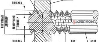
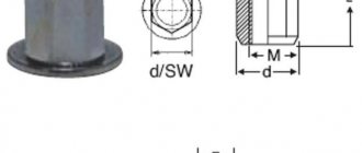
The main thread dimensions include diameters, profile, pitch and lead angle (Fig. 12.1).
Thread diameters: external d
, inner
d 1
and middle
d 2
.
The thread profile is the profile of the protrusion and groove in the plane of its section. Profile angle a
– the angle between adjacent sides.
Rice. 10.1. Basic thread parameters
The thread profile is also characterized by:
– height of the original thread triangle H
;
– working height of thread profile H1
.
Thread pitch P
– the distance between the nearest points of the same side sides of the thread profile.
For multi-pass threads, an additional term is introduced - screw stroke P h
, equal to the product of the thread pitch
P
and the number of starts
z
. (12.1)
For a single-start thread, the concepts of pitch and stroke are the same.
Rice. 12.2. Thread angle
Thread angle y
– the angle formed by the tangent to the helix. Let's expand the helix (Fig. 12.2) along the average diameter and determine the tangent of the thread's helix angle
. (12.2)
Threads by purpose
are divided into the following groups:
– fastening threads, designed for fastening parts. They are usually made with a triangular profile. The use of this profile is caused by increased friction, increased thread strength, and ease of manufacture.
– fastening and sealing threads are intended both for fastening parts and for protecting against leakage of liquids (in pipeline connections). These threads are made triangular, but without gaps.
– threads for transmitting motion (in lead and load screws). To reduce friction, these threads are made trapezoidal with symmetrical and asymmetrical profiles, and sometimes with a rectangular profile.
Threads in our country and abroad are standardized.
Metric thread
(Fig. 12.3) is standardized and is the main triangular thread in our country.
Rice. 12.3. Metric thread
It is characterized by a profile angle
a = 600, a cut of the screw thread profile apexes at a distance of H/8, and a nut thread profile apex at a distance of H/4. Height of the original thread triangle
.
Working height of profile
.
Working height of profile
.
Metric threads are divided into threads with large and small pitches. A thread with a large pitch is taken as the main one. Fine pitch threads are used for dynamic loads, parts in which the threads are used for adjustment. The pitches of all metric threads represent a stepped arithmetic series.
Metric threads with coarse pitch are designated by the letter M
and a number expressing the thread diameter in mm, for example
M20
.
For metric threads with fine pitches, the chain pitch is additionally indicated, for example M20 ´ 1.5
.
Pipe threads are standardized and used to connect pipes and pipeline fittings. Pipe thread is a fine inch thread, which is made with profile roundings and without gaps along the protrusions and recesses for better sealing. Due to the wide distribution of interchangeable parts with inch pipe threads, it retains its main use. For the main (nominal) size characterizing the thread and indicated in the thread designation, the nominal internal diameter of the pipe (clear passage) is used.
Tapered thread
standardized and ensures tightness without special seals. It is used for connecting pipes, installing plugs, etc. Impermeability is achieved by tightly fitting the profiles at the tops.
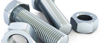
Mounting screws
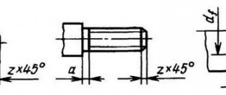
Depending on the type of threaded connection, the following types of mounting screws are used (Fig. 12.4):
– screws with nuts, called bolts (Fig. 12.4, a);
– screws screwed into one of the parts being fastened (Fig. 12.4, b);
– studs with nuts (Fig. 12.4, c).
Bolts are used to fasten parts of small thickness, when frequent unscrewing and screwing is necessary.
Screws are used when the part is sufficiently thick and strong and there is no room for a nut.
Read also: Gap between gate leaves
Studs are used in the same cases as screws, but when the material of the part does not provide the required strength during frequent disassembly and assembly.
Rice. 12.4. Main types of threaded connections
Steel bolts, screws and studs in accordance with the GOST 1759-70 standard are manufactured in 12 strength classes
The strength class is indicated by two numbers. The first number, multiplied by 100, indicates the minimum value of the tensile strength, the second, divided by 10, indicates the ratio of the yield strength to the tensile strength, and, therefore, their product represents the yield strength. For example, the strength class of a bolt is 4,6
has a tensile strength
s B = 4 × 100 = 400
MPa, a yield strength –
s T = (6/10) × 400 = 240
MPa;
with a bolt strength class of 10.9
,
s B = 10 × 100 = 1000
MPa, and
s T = (9/10) × 1000 = 900
MPa. If the dimensions are tight, threaded parts of a high accuracy class are used, which allows reducing the weight of the unit. In this case, the material of threaded parts is alloy steels such as 35Х, 40Х, 40Г2, etc. Heat treatment can increase the strength of threaded parts by 75%.
In the absence of increased requirements for metal consumption and when there is a danger of distortions of the supporting surfaces, threaded parts are selected from ductile steels of type 10, 20, 30, etc.
12.1.2. Screwing torque, efficiency and self-braking condition.
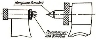
When considering the forces in a screw pair, it is convenient to rotate the thread along the average diameter into an inclined plane, and replace the nut with a slider (Fig. 12.5).
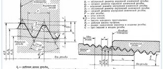
Profile
The main characteristic of any thread is its profile.
This name means a section of a threaded thread with a plane running along the axis of the product on which the thread is made. Angle, valley, peak - all these are profile elements. The angle formed by the side edges of the thread is called the profile angle. Its measurement is carried out in the diametrical plane.
As for the top of the profile, it is formed by a line that connects the side edges of the thread at the top point (E), as shown in Figure 1 below.
Figure 1. Profile elements
The depression of the profile in Figure 1, a, b is designated by the letter F. This is a line that also connects the side lines of the coil only at the lowest point. In other words, the valley is the lowest point of the helical groove.
The profile top/bottom shape can be of two types:
- flat-cut (a);
- rounded (b).
Metric thread. Diameters and steps.
According to GOST 8724 (ST SEV 181), metric threads can have a diameter of 0.25...600 mm. All diameters are divided into three rows.
Notes:
Thread designation.
The symbol for threads with large pitches should include: the letter M and the nominal diameter of the thread, for example M24, M64.
The designation of a fine pitch thread should include: the letter M, the nominal diameter of the thread and the numerical value of the pitch, for example, M24×2, M64×2, etc.
Thread classification
The thread can be directed either to the left or to the right, as shown in Figure 2.
Figure 2. Types of thread
You can determine the rise of the screw thread by looking at your hand. If you place a shaft with a threaded surface on the palm of your left hand, where the rise of the screw coincides with your thumb, then the thread is left-handed. Otherwise, the thread is right-handed. The type of thread determines in which direction the nut will be screwed: in the first case, the nut is screwed counterclockwise, and in the second case, clockwise.
The profile sets the type of thread:
- triangular;
- rectangular;
- trapezoidal;
- persistent.
It should be noted that triangular systems include metric, imperial and pipe threads. Each of them will be discussed.
Metric threads are considered the most popular. Moreover, threads are common, characterized by different pitch sizes (measured in mm). Their profile angle is 60°. Characteristic features of this design include the presence of play between the profiles of the bolt-nut threaded pair. Consequently, such threads are most often found on fasteners such as screws, bolts, studs, etc., the main purpose of which is to connect elements of mechanisms.
Inch threads are not as common as metric threads. Their profile angle is slightly smaller than the first ones, and is 55°, and the pitch is measured by the number of threads per inch. There is also play at the top and bottom points of this thread. Parts of foreign-made machines are equipped with such threads, so they are manufactured as needed (when the original product fails).
The profile angle of the pipe thread coincides with the inch thread and is 55°. A distinctive feature of this type of thread is the rounded shape of the peaks and valleys, as well as the absence of gaps at these points. Due to this, this threaded connection is waterproof. Gas and water pipes and their connecting elements (for example, couplings) are equipped with such threads.
Trapezoidal thread is characterized by a trapezoidal profile and an angle of 30°. The profile is formed by straight lines, slightly rounded at the top and bottom points where gaps are expected. Its use is relevant on screws that convert the rotation of one part into the linear movement of another.
A rectangular thread is distinguished by a square profile, each face of which is equal to half a pitch. There is no backlash here. The scope of its application is exactly the same as in the case of trapezoidal threads. However, it is extremely rare to encounter it, since it is not standardized.
When connecting, the thrust thread is in contact with the sides that bear the main load, as well as with the upper and lower thread points of the connected elements. There is a gap between other profile elements. Similar threads are made on couplings that connect pipelines of compressors and compressed air tanks, and on hydraulic press screws.
Threaded connections. Thread angle. Preparation method. Geometric parameters.
Threaded connections are the most common type of detachable connections. They are carried out using fastening threaded parts (bolts, screws, studs, nuts, etc.) Advantages
: reliability, ease of assembly/disassembly, simplicity of design, low cost (due to standardization), manufacturability, ability to adjust the compression force.
Disadvantages:
stress concentration in the thread gullies, low vibration value.
On the development of a cylindrical surface, the helix is located at a certain angle ψ
, this angle is called the thread lead angle.
- thread stroke, which is the distance between the same points of one helix. The main characteristic of a thread profile is the angle between adjacent flanks in the plane of the axial section, called the thread profile angle. For triangular profile metric, inch, trapezoidal threads.
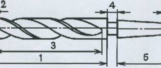
There are two main methods for making threads: cutting and rolling. Thread cutting is carried out with cutters, combs, dies, taps, threaded heads, and milling cutters. Thread rolling is carried out using combs or rollers on thread rolling machines by plastic deformation of the workpiece. This method is highly productive and is used in mass production for the manufacture of standard fasteners.
The main geometric parameters of cylindrical threads are:
d
– outer diameter (nominal thread diameter);
d1
- internal diameter of the nut thread;
d2
- average thread diameter, i.e.
the diameter of an imaginary cylinder on which the thickness of the coil is equal to the width of the cavity; p
- thread pitch, i.e.
the distance between the same sides of two adjacent turns in the axial direction; ph
- thread stroke, i.e.
the distance between like sides of the same turn in the axial direction; α
—thread profile angle;
42. Friction moment in the thread and at the end of the nut (screw). Calculation of threads for bearing and shear stress. Nut height and screwing depth.
The vast majority of threaded connections are pre-tightened. The tightening is created during assembly in order to prevent the joint from opening or moving the parts being connected after the application of the working load.
When screwing a nut (or a screw with a head), it is necessary to apply a screwing torque Tsav to overcome the resistance moment TP in the thread and the resistance moment TT at the end of the nut:
Tzav = TP + TT, (2.1)
where TP = Ft d2 / 2 = 0.5 Fzatd2tg(Ψ + φ1) ; (2.2)
CT = 0.5 FzatfTdav , (2.3)
Fzat – axial tightening force;
d2 – average thread diameter;
Ψ – thread lead angle;
φ1 – reduced (taking into account the influence of the profile angle α) friction angle in the thread: φ1 = φ / cos(α/2),
φ – friction angle of materials of the screw-nut pair;
fT is the coefficient of friction of the materials of the nut-workpiece pair;
dav – average diameter of the ring (Fig. 2.2):
dav = 0.5(D + dh).
The operation of threaded connections shows that failure of bolts, screws, studs, etc. parts occurs due to the rupture (or stretching) of their rod along the thread or transition section at the head. Destruction or damage to thread elements occurs less frequently and is typical for parts that are often subjected to disassembly and assembly. If necessary, perform verification calculations of the thread for strength based on shear and crushing stresses.
The thread shear strength condition has the form
τcp= Q/Аcp) ≤[τcp],
where Q is the axial force; Аср – cutting area of the cutting turns; for a screw (see Fig. 1.9) Asp = πd1kHg, for a nut Asp = πDkHg. Here Ng is the height of the nut; k is a coefficient that takes into account the width of the base of the threads: for a metric thread for a screw k≈ 0.75, for a nut k≈ 0.88; for trapezoidal and thrust threads (see Fig. 1.11, 1.12) k≈ 0.65; for rectangular thread (see Fig. 1.13) k= 0.5. If the screw and nut are made of the same material, then only the screw is checked for shearing, since dl
The condition for the thread's crushing strength has the form
σcm= Q/Acm≤[σcm],
where Acm is the conditional crush area (projection of the contact area of the thread of the screw and nut onto a plane perpendicular to the axis): Acm = πd2hz, where (see Fig. 1.9) nd2 is the length of one turn along the average diameter; h – working height of the thread profile; z=Нг/р – number of thread turns in a nut with height Нг; p – thread pitch (according to the standard, the working height of the thread profile is designated H1).
The required height of the nut is determined from the condition of the bolt shaft being equal in tensile strength under the influence of axial load and the nut thread in bending, shearing and crushing. It has been established that the first thread turn from the point of application of force absorbs 34% of the total load, the second - 23%, the third - 15%, and the tenth - only 0.9%. Thus, all turns of the nut thread after the tenth do not take up practically any load.
Just like the threads of a nut, the threads of the socket into which the screw or stud is screwed work. Depending on what material the parts into which the studs are screwed are made of, the depth of screwing of the studs also changes. Here the magnitude of the axial load is already taken into account, because the greater it is, the larger the diameter of the stud, and the, therefore, the greater the depth of screwing.
Tolerance fields
The fit of the outer profile into the inner one depends on the working height - the maximum amount of contact between the sides of the profiles of the connecting elements. It is expressed through thread tolerance fields.
The reliability of the connection, where fluctuations within it are minimized, is indicated by the first or exact tolerance class. The most common is the second (middle) class. The third (rough) class indicates a large deviation.
Tolerances on the dimensions of metric threads are indicated through the values of two diameters: the average and the diameter of the protrusions.
When forming a metric thread, data is taken from the corresponding tables (GOST 16093-2004). The selection of tolerance fields is carried out according to the rules of priority:
- first priority – values indicated in bold;
- the second - in regular font;
- third – values taken in parentheses;
- extraordinary – values in square brackets (for special products).
It is possible to use tolerances that are not indicated in the tables, but are formed from the ratios of existing standard diameters.
External thread tolerance fields
Internal thread tolerance fields
It is important that the protective coatings of parts in their geometric parameters do not exceed the value of the nominal profile, therefore in such cases tolerances are used even before applying the protective layer.
Application
Metric threads are widespread in the countries of the former Soviet Union. Used for application to both internal and external planes of fasteners. Typically used for fastening metal structures of various types. For these purposes, a variety of bolts (anchor and conventional) and other types of fasteners are manufactured. She found a particular purpose in mechanical engineering, construction of engineering communications, especially in the plumbing sector. Most pipe and container fittings are manufactured with this type of thread.
Most often, this type of carving is applied to cylindrical objects. But in some cases, when it is necessary to achieve tightness, a conical shape is used. This form, with a metric thread applied, allows you to achieve maximum tightness, even without the use of additional sealing agents. Most often used for installation of pipelines.
Read also: Repair of asynchronous electric motors with a wound rotor
Main settings
Each thread has precise geometric parameters. Metric is characterized by a triangular thread profile, which is also called fastening. It is used for parts connected to each other by screwing. The profile size is determined by its height.
The profile height (H) is the segment from the base to the top of an equilateral triangle, which is formed by a transverse section of the coil. The protrusions and depressions are made in the form of triangles with cut off vertices. In some cases, the depressions are rounded.
If the sides of each turn are mentally extended to the point of their intersection, then they will form a profile angle (α).
The main parameters indicated in the designation of a metric thread characterize its size. These include diameter and pitch. Metric thread designations indicate the main parameters.
Thread diameter is divided into 4 types:
Thread parameters such as stroke (Ph) and pitch (P) are interdependent and equal for a single-start system.
Thread stroke and pitch
The section separating the points of the same name on two turns is the thread pitch. There are main steps (large) and small steps.
Thread lead is a segment connecting two identical points on adjacent turns of the same thread. In the case where there are several entries, the move is expressed through the product of the number of steps and the number of entries.
The main thread elements also include:
- A surface inclined 45º in front of the inner or behind the outer is called a chamfer. It plays a role in connecting elements.
- Run-off is the place of transition to the uncut surface of the part. These two indicators are united by length, that is, a segment with turns, chamfer and runoff.
For metric threads, the main dimensions are summarized in tables of the relevant standards: GOST 9150-2002, GOST 8724-2002, GOST 24705-2004.
Possible structural deviations caused by the properties of materials are reported by tolerance fields, with values not exceeding the nominal profile formed by the maximum of the material. These indicators affect the accuracy of the thread fit - the density of penetration of the protrusions into the gaps.
Thread tolerance fields are divided into three accuracy classes. And also 4 types according to your preference.
Designation principles
The designation of threads in drawings is carried out according to the following rules.
- Indicate with solid thin and thick lines. The designation of an internal thread is a thin line along the outer diameter and a thick line on the internal one, and an external thread is indicated by a thick line along the outer diameter and a thin line on the internal one.
- If the part is projected onto a plane along the axis of rotation, then it is shown as solid straight lines. If - across, then this is an open contour, 0.75 of the total circumference. The ends of the arc should not lie on the axes of the part in the figure.
- The gap between the thin and thick lines should be more than 0.8 mm, but less than the step size.
- When designating metric threads in drawings perpendicular to the axis, chamfers are depicted only with structural significance.
External and internal thread types
Metric threads are standardized by several documents: GOST 8724-2004, GOST 2470-2004, GOST 9150-2002, GOST 1693-2005. They specify the requirements for dimensions, profile, pitches and tolerances.
Based on the product labeling, you can determine all the necessary parameters and type. Entry includes:
- a capital letter characterizing the type, or two capital letters - a type and a subspecies (for example, metric - M; metric conical - MK);
- a number expressing the nominal diameter in millimeters (M20 - metric with a nominal diameter of 20 mm);
- in the case of a small step, indicate its value in millimeters, using the multiplication sign - M20x1.5;
- in the case of a multi-start, add an indication of the stroke after the “x” and the step in parentheses - M20x3(P1) - metric with a diameter of 20 mm, three-start, where the step is 1 mm;
- when designating a left-hand thread, the Latin capital letters “LH” are written - M20LH or M20x3(P1)LH - also only left-handed.
In some cases, the marking may include additional parameters: make-up length, tolerances and fit. Their decoding is as follows:
- indication of tolerance for external thread M12x1.75-6g and for internal thread M12-6N;
- make-up length is expressed in capital Latin letters - S - shot (short), N - normal (normal), L - long (long), sometimes a numerical value of the length in millimeters is added in parentheses if the value is non-standard; for example, M12-6g-L(30);
- the fit is expressed as a fraction through the tolerance values for internal (numerator) and external (denominator) threads, for example, taking into account how left-hand threads are designated, the general appearance will be M12x1-6H/6g-LH.
The marking may also indicate the type and number of the standard.
By choosing the right type of metric thread and its geometric parameters, you can ensure high-quality fastening of parts, long-term operation of the product and savings on repairs and maintenance.
If you find an error, please select a piece of text and press Ctrl+Enter.
What is the profile angle of a metric thread?
GOST 9150-2002 (ISO 68-1-98)
Basic norms of interchangeability
Basic norms of interchangeability. Metric screw threads. Profile
MKS 21.040.10 OKSTU 0071
Date of introduction 2004-01-01
1 DEVELOPED by the Research and Design Institute of Measuring Instruments in Mechanical Engineering (JSC NIIizmereniya)
2 INTRODUCED by Gosstandart of Russia
3 ADOPTED by the Interstate Council for Standardization, Metrology and Certification (Protocol No. 22 of November 6, 2002)
The following voted for adoption:
Name of the national standardization body
State Standard of the Republic of Belarus
Gosstandart of the Republic of Kazakhstan
4 This standard is identical to the international standard ISO 68-1-98 “ISO threads for general purposes. Main profile. Part 1. Metric thread" and contains additional requirements reflecting the needs of the country's economy
5 By Decree of the State Committee of the Russian Federation for Standardization and Metrology dated June 23, 2003 N 200-st, the interstate standard GOST 9150-2002 (ISO 68-1-98) was put into effect directly as a state standard of the Russian Federation from January 1, 2004.
State standards
GOST 8724-2002
State standard containing standards defining the required parameters of metric threads, including pitch and diameter. Adopted in 2002, with subsequent editions, as an analogue of the international standard ISO 261-98. The GOST text practically repeats the international text, with one difference: the ISO range ranges from 1 to 300 mm, this standard has been expanded to the range from 0.25 to 600 mm. The last revision of the text was made in 2004 and is valid today.
The standard contains individual parameters that can also be found in other standards. The structure of the document is similar to other standards of this type. All information is structured in the form of tables containing requirements for thread pitch and diameter. This test structure is as convenient as possible for understanding and use.
It should be noted that the regulatory information applies to threads of all types, be it left-handed or right-handed. The standard establishes the standard value of metric thread steps in the range from 0.075 to 8 mm.
The document consists of:
- Prefaces. Which contains general information about GOST, by whom and when it was adopted, when changes were made.
- Scope of application. Information is provided on the range of regulatory requirements for size and pitch.
- Links to standards.
- Definitions.
- Table of diameters and pitch. The section contains a table of standard indicators.
- Thread designation. Labeling standards are indicated.
GOST 24705-2004
The standard was adopted in 2004. Its standards apply to all types of threads in accordance with GOST 8724. The text information is also structured in the form of a table. Complies with the international standard ISO 724:1993 with additions in accordance with the exclusive requirements of each member country of the Interstate Council for Standardization.
GOST 9150-2002
A standard regulating the requirements for the profile, namely the geometric parameters. Adopted in 2002 and covering all types of threads. The text of GOST is closely related to the above standards.
GOST 16093-2004
Adopted in 2004. Regulates the standard tolerance of threads and markings, applies to different types. The latest version contains the provisions of the international standard.
The above standards are applied in combination, as they complement and refer to each other.