During various switching processes using electromagnetic starters, relays, contactors and other equipment, the electrical resistance in the switching element changes. In these devices, this function is performed by the gap between the contacts. In the closed state, the resistance becomes very small, and as the contacts open, it begins to increase.
Such changes occur very quickly, in an abrupt manner, and are accompanied by a chain break. In some cases, it is necessary to avoid such a break, so non-contact devices are used in such switching circuits. A typical representative of this group is a thyristor contactor, which includes thyristors that have a nonlinear electrical resistance that can change upward or downward.
Thyristor load switches (10 circuits)
Thyristors are often used to turn on and off loads (incandescent lamps, relay windings, electric motors, etc.). The peculiarity of this type of semiconductor devices and their main difference from transistors is that they have two stable states, without any intermediate ones.
It is an "on" state when the resistance of the semiconductor device is minimal, and an "off" state when the resistance of the thyristor is maximum. Ideally, these resistances approach zero or infinity.
To turn on the thyristor, it is enough to apply the control voltage at least briefly to its control electrode. You can turn off the thyristor (lock it) by briefly turning off the power to the thyristor, changing the polarity of the supply voltage, or reducing the current in the load below the holding current of the thyristor.
Typically, thyristor switches are turned on and off using two buttons. Single-button thyristor control circuits are much less common.
Methods for one-button control of thyristor switches are discussed in detail here. The operating principle of thyristor single-button control devices is based on dynamic charge-discharge processes in the thyristor control circuit [EW 4/01-299].
Single-button thyristor control circuit
Figure 1 shows one of the simplest single-button control circuits for a thyristor switch. In the diagram (hereinafter) buttons are used without fixing the position. In the initial state, the normally closed contacts of the button bypass the thyristor control circuit.
The thyristor resistance is maximum, no current flows through the load. Diagrams of the main processes occurring in the circuit in Fig. 1, are discussed in Fig. 2.
To turn on the thyristor (ON), press the SB1 button. In this case, the load is connected to the power source through the contacts of the SB1 button, and capacitor C1 is charged through resistor R1 from the power source.
The charging rate of the capacitor is determined by the time constant of the circuit R1C1 (see diagram). After the button is released, capacitor C1 is discharged to the control electrode of the thyristor. If the voltage across it is equal to or exceeds the turn-on voltage of the thyristor, the thyristor is unlocked.
Rice. 1. Schematic diagram of controlling a thyristor using one button.
Rice. 2. Diagrams of the main processes occurring in a circuit with a thyristor.
You can turn off the load (OFF) by briefly pressing the SB1 button. In this case, capacitor C1 does not have time to charge. Since the button contacts bypass the thyristor electrodes (anode - cathode), this is equivalent to turning off the thyristor's power supply. As a result, the load will be disconnected.
Therefore, to turn on the load, you need to press the control button for a longer time, and to turn it off, briefly press the same button again.
Simple power switches based on thyristors
In Fig. 3 and 4 show variants of the circuit idea presented in Fig. 1. In Fig. 3, a chain of series-connected diodes VD1 and VD2 is used to limit the maximum charging voltage of the capacitor.
Rice. 3. A variant of the thyristor control circuit with one button.
This made it possible to significantly reduce the operating voltage (to 1.5...3 V) and the capacitance of capacitor C1. In the following circuit (Fig. 4), resistor R1 is connected in series with the load, which allows you to create a two-pole load switch. The load resistance should be much lower than R1.
Rice. 4. Circuit diagram of an electronic key based on a thyristor with a serial load connection.
Thyristor switch with two buttons
A thyristor load control device (Fig. 5) can be used to turn the load on and off using any of several buttons connected in series that operate to open the circuit. The operating principle of a thyristor switch is as follows.
When the device is turned on, the voltage supplied to the control electrode of the thyristor is not enough to turn it on. The thyristor, and, accordingly, the load is turned off. When you press any of the buttons SB1 - SBn (and hold it pressed), capacitor C1 is charged through resistor R1 from the power source. The thyristor control circuit and the thyristor itself are disabled.
Rice. 5. Diagram of a simple thyristor load switch with two buttons.
After releasing the button and restoring the thyristor power circuit, the energy accumulated by capacitor C1 is applied to the control electrode of the thyristor. As a result of the discharge of the capacitor through the control electrode, the thyristor turns on, thereby connecting the load to the power circuit.
To turn off the thyristor (and load), briefly press any of the buttons SB1 - SBn. In this case, capacitor C1 does not have time to charge. At the same time, the thyristor's power supply circuit opens and the thyristor turns off.
The value of resistor R2 depends on the supply voltage of the device: at a voltage of 15 V its resistance is 10 kOhm at 9 V - 3.3 kOhm at 5 6-1.2 kOhm.
Circuit with the equivalent of a thyristor on transistors
When using its transistor analogue instead of a thyristor (Fig. 6), the value of this resistor changes, respectively, from 240 kOhm (15 V) to 16 kOhm (9 V) and to 4.7 kOhm (5 V).
Rice. 6. Scheme of an electronic load switch with a transistor equivalent of a thyristor.
Analogue of a multi-button switch using thyristors
A thyristor device that makes it possible to create an analogue of a multi-button switch with dependent position fixation and uses push-button elements operating without fixation for control is shown in Fig. 7. Several thyristors can be used in the circuit, however, to simplify the circuit, only two channels are shown in the figure. Other switching channels can be connected similarly to the previous ones.
Rice. 7. Schematic diagram of an analog multi-button switch using thyristors.
In the initial state, the thyristors are locked. When you press a control button, for example, button SB1, capacitor C1 of a relatively large capacity is connected to the power source through diodes VD1 - VDm and load resistances of all channels.
As a result of charging the capacitor, a current pulse occurs, leading to a short-circuit of the anodes of all thyristors through the corresponding diodes VD1 - VDm to the common bus.
Any of the thyristors, if it was turned on, turns off. At the same time, the capacitor stores energy. After releasing the button, the capacitor is discharged onto the control electrode of the thyristor, unlocking it.
To turn on any other channel, press the corresponding button. The previously involved load is disconnected (reset) and a new load is turned on. The circuit provides a button SB0 for general shutdown of all loads.
Multi-button switch with transistor analogue of thyristors
A version of the circuit, made on transistor analogues of thyristors and diode-capacitive charging circuits using small capacitors, is shown in Fig. 8, 9.
Rice. 8. Diagram of equivalent replacement of a thyristor with transistors.
The circuit provides LED indication of the activated channel. In this regard, the maximum load current of each channel is limited to 20 mA.
Rice. 9. Diagram of a multi-button switch with a transistor analogue of thyristors.
Devices similar to those shown in Fig. 7 - 9, as well as in Fig. 10 - 12, can be used for program selection systems for radio and television receivers.
The disadvantage of circuit solutions (Fig. 7 - 9) is that at the moment you press any of the buttons, all loads are at least momentarily connected to the power source.
Multi-position switch circuits
In Fig. 10 and 11 show a thyristor switch of a discontinuous type with an unlimited number of series-connected elements.
When one of the control buttons is pressed, the power supply circuit of the thyristor analogues opens to DC current. Capacitor C1 is connected in series with the thyristor analogue.
Rice. 10. Diagram of the basic element for a homemade multi-position load switch.
Rice. 11. Schematic diagram of a homemade multi-position load switch.
At the same time, the control voltage (zero level) through the activated button and resistor R2 (Fig. 10) is supplied to the control electrode of the thyristor analogue.
Since in the first moments when the button is pressed, a completely discharged capacitor turns on in series with the thyristor analogue, such inclusion is equivalent to a short circuit in the power circuit of the corresponding thyristor. Consequently, the thyristor is turned on, thereby turning on the corresponding load.
When you press any other button, the previously activated channel is turned off and another channel is turned on. When you press any button for a long time (about 2 seconds), capacitor C1 is charged, which is equivalent to opening the circuit and leads to the locking of all thyristors.
Advanced Electronic Switch Circuit
Rice. 12. Schematic diagram of a thyristor switch for multiple loads.
Among the thyristor switches, the most advanced is the circuit shown in Fig. 12. When the control button is pressed, an inrush current occurs, equivalent to a short circuit.
The previously activated thyristors are turned off and the thyristor corresponding to the pressed button is turned on. The circuit provides an LED indication of the involved channel, as well as a general reset button.
Instead of high-capacity capacitors, diode-capacitor chains can be used (Fig. 12). The operating principle of the circuit remains the same. As a load, you can use low-voltage relays, for example, RMK 11105 with a resistance of 350 Ohms for an operating voltage of 5 V.
Resistor R1 limits the short circuit current and the maximum consumption current to 10... 12 mA. The number of switching channels is not limited.
Literature: Shustov M.A. Practical circuit design (Book 1), 2003.
Thyristor contactor TK-3-RL
Thyristor contactor (other names - thyristor starter, contactless starter, thyristor switch) TK-3-RL is designed for switching alternating voltage to an active-inductive load - electric motors, heating elements, etc.
Compared to conventional mechanical contactors, thyristor contactors have the following advantages:
- absence of mechanical contacts, which, as a result, eliminates the need for periodic maintenance and replacement of worn contacts;
- quiet operation;
- absence of an electric arc when switching on and off;
- frequency of switching on and off is practically unlimited;
Unfortunately, the price for these advantages is a higher price, as well as heat dissipation from the thyristors. However, in some cases the use of thyristor contactors is vital.
The table below lists their main technical characteristics.
Table 1 – Technical characteristics of TK-3-RL
| Number of phases | 3 |
| Net | 198-242 V, 342/418 V, 50 Hz |
| Phase control | Joint and separate |
| Load connection diagram | “star”, “triangle”, “star” with working neutral, “open delta” |
| Auxiliary power for control system | 198-242 V 50 Hz |
| Control system power consumption | 20 VA |
| Rated load current In | 100, 160, 200, 250, 315, 400, 500, 630, 800, 1000, 1250, 1600 A |
| Switching element | Thyristor |
| Control system type | Analog |
| Control signal | “dry” contact, transistor with a collector-emitter (or drain-source) breakdown voltage of at least 15 V |
| Indication | 4 LEDs |
| Additional contacts | 2 “Operation” relays with changeover contacts |
| Protection: thyristor overheating | Temperature sensor 80 C |
| Overload capacity(rms value) | I=3 In – 3 sec, I=2 In – 5 sec, I=1.5 In – 10 sec, I=1.25 In – 30 sec, I=1.1 In – 1 min |
| Degree of protection | IP00, IP20 |
| Cooling | Forced by built-in fans |
| Fan life | 50000 hours |
| Ambient temperature | 0..45 C |
| Relative humidity | 0..90% without condensation (dry room) |
| Insulation | 2.5 kV between chassis, power circuit and control circuits |
| Operating mode | Long-term, duty cycle = 100% |
| Lifetime | At least 10 years |
| Guarantee | 12 months from date of sale |
Table 2 Additional equipment and services
| Reverse board | For reverse motor control |
| Power supply 3x500 or 3x660 V | Power supply with non-standard mains voltage |
| Protection degree IP54, IP66 Street or marine version | The thyristor contactor is installed in a sealed cabinet |
| Express production within 2-3 working days. | |
| Spare parts kit | A spare set of boards and thyristors allows, if necessary, to carry out independent repairs within 1-2 hours |
Thyristor starters are available in two design modifications - IP00 and IP20 versions. Both options are supposed to be mounted in a cabinet, but if the room is dry and the air is clean and does not contain conductive dust, then a cabinet is not necessary for the IP20 design.
Thyristor contactor TK-3-RL can be used to control a three-phase load (voltage switching of all three phases simultaneously - joint phase control), and to supply voltage in phases to three single-pole loads (separate phase control). Separate phase control is only possible with “star” load connection circuits with a working neutral or “open delta”.
When selecting a thyristor starter for controlling an asynchronous electric motor, one should take into account the starting currents of the electric motor, which are 5-7 times greater than its rated current, as well as the starting duration and overload capacity of the contactor (see Table 1). To ensure a long service life of the contactor, it is necessary to select its current rating with some margin, otherwise the thyristors will gradually degrade and fail.
Table 3 Recommended current ratings of TK-3-RL thyristor starters for asynchronous electric motors
| Asynchronous electric motor, kW | Contactor in, starting duration 3-5 seconds | Contactor in, starting duration 7-10 seconds | Contactor in, starting duration 15-20 seconds |
| 7,5 | 100 | 100 | 100 |
| 11 | 100 | 100 | 100 |
| 15 | 100 | 100 | 160 |
| 18,5 | 100 | 160 | 160 |
| 22 | 160 | 160 | 200 |
| 30 | 160 | 200 | 250 |
| 37 | 200 | 250 | 315 |
| 45 | 250 | 315 | 400 |
| 55 | 315 | 400 | 500 |
| 75 | 400 | 500 | 630 |
| 90 | 500 | 630 | 800 |
| 110 | 630 | 800 | 1000 |
| 160 | 800 | 1000 | 1250 |
| 200 | 1000 | 1250 | 1600 |
| 220 | 1250 | 1600 | — |
If it is necessary to organize reversible control of the electric motor, two thyristor contactors will be required, and to prevent the simultaneous activation of contactors, it is necessary to install an additional reverse board, which provides a guaranteed pause between switching of contactors of 30-50 ms.
Figure 1 Reverse board
Designations when ordering:
Documentation:
Thyristor contactor TK-3-RL, version IP00 Operating manual
Thyristor contactor TK-3-RL, version IP20 Operating manual
Prices for thyristor contactors TK-3- RL :
Thyristor contactors TK-3-RL PRICE LIST
Urgent order - plus 25% of the cost, but not less than 15 thousand rubles. It is recommended to inquire in advance about the possibility of urgent fulfillment of a specific order.
Thyristor Contactor: AC Switch
During various switching processes using electromagnetic starters, relays, contactors and other equipment, the electrical resistance in the switching element changes. In these devices, this function is performed by the gap between the contacts. In the closed state, the resistance becomes very small, and as the contacts open, it begins to increase.
Such changes occur very quickly, in an abrupt manner, and are accompanied by a chain break.
In some cases, it is necessary to avoid such a break, so non-contact devices are used in such switching circuits.
A typical representative of this group is a thyristor contactor, which includes thyristors that have a nonlinear electrical resistance that can change upward or downward.
Operating principle of a thyristor contactor
The operation of a thyristor contactor is based on contactless switching. This physical phenomenon consists in the changing conductivity of semiconductors connected to the circuit along with the load.
During operation, there are no visible breaks in the circuit, and the process itself is as follows: when the circuit is turned off, the conductivity of the semiconductor decreases sharply, and the resistance can reach several tens of megohms.
After switching on, the conductivity of the element is restored, and the resistance tends to zero and is measured in milliOhms (mOhm).
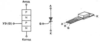
Semiconductor devices are various types of triacs, thyristors and transistors, connected in series with the load in an electrical circuit. Their action is based on the phenomenon of electron-hole transition (p-p), providing one-way conductivity from the anode (p) to the cathode (p).
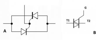
The same principles apply to the operation of a thyristor contactor or AC switch. The most commonly used circuits are those with back-to-back connections of thyristors VS1 and VS2, marked in the figure.
Pulses are generated by the control unit when the voltage passes through the zero mark. Under the influence of pulses, the thyristors open one by one, due to their shift between themselves by 180 degrees. As a result, a sinusoidal alternating current begins to move in the circuit.
When the instantaneous value of the load current decreases, the thyristors turn off.
Electronic ballasts for fluorescent lamps
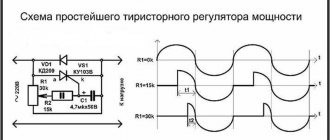
The amount of current at which switching occurs is called the holding current. The alternate arrival of pulses from the control unit causes the same periodic closing and opening of the thyristors.
In practice, the presented circuit works as follows. After pressing the SB1 button, current will flow through the electronic time relay KT.
This will cause the CT contact to close in the control circuit and thyristors VS1 and VS2 become conductors: the first with a positive half-wave, and the second with a negative half-wave of voltage. This conductivity is maintained as long as the QD contacts are closed.
At the end of the time delay, the contacts open and voltage no longer flows to the control electrodes. Conductivity is lost and the circuit breaks.
All these actions occur in a very short time, just enough for the resistance welding used as an example. Such an operating mode can only be provided by a thyristor contactor in combination with an electronic time relay. The required polarity of the control current is provided by diodes VD1 and VD2 connected to the corresponding thyristors.
This type of contactor is designed to operate with alternating current. It is considered uncontrollable because it does not have control over the current load. Such contactors provide only the duration of this load, due to a certain number of half-waves set by an electronic time relay.
Thyristor DC contactors
DC contactors have a number of individual features and characteristics. One of them is the ability to work with much higher switching frequencies during adjustments and conversions of current and voltage.
In this they differ markedly from thyristor regulators that provide stabilization in circuits with alternating current.
DC devices provide a higher level of performance, and this factor largely determines the scope of their use.
Transformerless power supply
However, these devices sometimes have individual requirements. For example, if necessary, a thyristor contactor must be switched on for a minimum period of time.
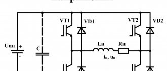
Therefore, conventional electromagnetic contactors can be used together with a thyristor device, forming a combined circuit. Their main function is to timely turn off the thyristor. When connected in parallel (Fig.
3a) the thyristor is turned off by shunting it using the NO contact K.
If a serial connection is used (Fig. 3b), this operation is carried out by the breaking contact K. Such a combined circuit is turned on by a control pulse supplied to the thyristor VS.
Thyristor contactors are classified according to the switching method. The main feature is considered to be the connection between the switching on and off of the thyristor, produced due to general electromagnetic processes that capture the switching circuit. In different cases, switching can be one-, two- and three-operational or one-, two- and three-stage.
If there are two stages of switching, the main thyristor starter can be turned off regardless of when it was turned on.
In such circuits, a special switching circuit is used to turn off, connected to the main element through an additional thyristor.
Therefore, the process of turning off the contactor in this case is considered a second work operation, performed independently of other actions. To implement this, a control pulse is supplied to the switching thyristor.
The three-operation scheme may include one more additional operation, if required by technical operating conditions. Theoretically, the number of stages can be increased without any restrictions, but such multi-stage schemes are not used in practice.
Advantages and disadvantages
The undoubted advantages of thyristor contactors in comparison with conventional devices are as follows:
- With regular switching on and off, there is no electric arc causing destruction of contacts of electromagnetic devices.
- The short response time makes it possible to perform frequent switchings, with virtually no restrictions. Operating modes can be not only long-term, but also short-term.
- There are no moving parts subject to mechanical wear. Therefore, the service life of thyristor contactors is much longer than that of conventional devices.
- Silent operation due to design features.
- Very easy repair and maintenance. Any part of the contactor can be easily replaced within a short time without dismantling the main device.
- If necessary, the thyristor contactor can be easily converted to a different current rating. To do this, install a suitable thyristor with the appropriate technical characteristics.
Electrical capacitance of a flat capacitor
Even these perfect devices have certain disadvantages:
- There is no physical circuit break or galvanic isolation, which reduces the level of safety during operation of the device.
- They have a smaller commutation depth compared to standard contact devices.
- Increased weight, dimensions, relatively high price.
Scope of application of thyristor contactors
According to their technical characteristics, thyristor contactors turned out to be most suitable for use in the following operations:
- Heavy and prolonged starting with high loads, typical, for example, of centrifugal and axial fans.
- When creating a significant load on the network during startup, which leads to voltage sags and false alarms. Installing a thyristor contactor allows you to reduce the starting current by about 3 times.
- A large number of switches on and off in a short period of time.
- Starting high power engines, especially at high speeds. The electrodynamic impact on the unit is reduced.
- In soft start systems provided for by technological processes.
Thyristor starter, assemble a starter from T161 thyristors
9.1.14. Amplifier UVB-11-19-3721: a -
symbol;
b
- functional diagram
with contact K
occurs spontaneously at the first transition of the load current through zero.
In order for the circuit to be controlled by logical signals from other elements, a matching stage is provided on an IC of type K511LI1, the output of which is connected to the winding of the reed relay K.
In amplifiers intended for switching load circuits
DC, this switching is carried out by a thyristor, which is turned off using a forced switching circuit, i.e., by discharging a pre-charged capacitor onto the thyristor.
LECTURE No. 30
9.2. Microprocessors and electronic control machines
9.2.1. General information.
9.2.2. Functional diagram of a computer.
9.2.3. Electronic and microprocessor devices, their classification and
physical phenomena in them.
9.2.4. Functional diagram of DC motor control
current using a microprocessor.
General information
Currently, to improve technical characteristics, increase reliability and reduce installation time, automatic control and regulation devices for electric drives are made in the form of complete control stations (KSU). These stations are designed according to standard designs and assembled at the manufacturing plant using the most high-performance equipment, which leads to a reduction in material and labor intensity and allows for the rapid implementation of the latest achievements of science and technology. CSUs are created on the basis of either traditional electromagnetic devices (automatic machines, starters, contactors, relays), or discrete semiconductor elements, or the joint use of both products. The CCS is characterized by a fixed sequence of all functional operations. Any change to a previously set functional task requires reinstallation of the circuit diagram of the control unit and subsequent adjustment, which is associated with the cost of additional labor and time. Therefore, the software control systems currently being created for metal-cutting machines, robots, and technological processes require an easily changeable control program.
The development of semiconductor technology has led to the creation of large
Rice. 9.2.1. Functional diagram of a computer
integrated circuits (LSI) with a very high degree of integration. LSIs on a single chip have several tens of thousands of elements and are capable of implementing highly complex control functions. Application of LSI in complete
automatic control devices creates exceptionally wide opportunities for flexible changes in their programs, reducing dimensions, increasing reliability and durability. Microprocessors are created on the basis of LSI.
Date added: 2017-05-02; ;
Operating principle of a three-phase alternating current thyristor starter
During various switching processes using electromagnetic starters, relays, contactors and other equipment, the electrical resistance in the switching element changes. In these devices, this function is performed by the gap between the contacts. In the closed state, the resistance becomes very small, and as the contacts open, it begins to increase.
Such changes occur very quickly, in an abrupt manner, and are accompanied by a chain break.
In some cases, it is necessary to avoid such a break, so non-contact devices are used in such switching circuits.
A typical representative of this group is a thyristor contactor, which includes thyristors that have a nonlinear electrical resistance that can change upward or downward.
Advantages and disadvantages
The undoubted advantages of thyristor contactors in comparison with conventional devices are as follows:
- With regular switching on and off, there is no electric arc causing destruction of contacts of electromagnetic devices.
- The short response time makes it possible to perform frequent switchings, with virtually no restrictions. Operating modes can be not only long-term, but also short-term.
- There are no moving parts subject to mechanical wear. Therefore, the service life of thyristor contactors is much longer than that of conventional devices.
- Silent operation due to design features.
- Very easy repair and maintenance. Any part of the contactor can be easily replaced within a short time without dismantling the main device.
- If necessary, the thyristor contactor can be easily converted to a different current rating. To do this, install a suitable thyristor with the appropriate technical characteristics.