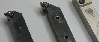
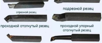
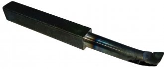
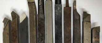
Thread cutting on a lathe is one of those operations for which various tools can be used. This problem is most often solved using a cutter. In addition to it, taps, dies, and special-purpose working heads are also used. In addition, on lathes this operation can be performed using knurling technology.
The process of cutting threads on a lathe with a cutter
Design and dimensions
Carbide-tipped thread turning tools. Design and dimensions
GOST
18885-73
In place of MH 623-64; MH 624-64; MH 625-64; MH 626-64
ISS 25.100.10
By Decree of the State Committee of Standards of the Council of Ministers of the USSR dated June 8, 1973 No. 1429, the date of introduction was established
01.07.74
The validity period was removed by Decree of the USSR State Standard of 02.12.81 No. 655
1. This standard applies to general purpose turning thread cutters with carbide inserts.
(Changed edition, Amendment No. 1).
2. Cutters must be made of the following types:
1 - threaded for external metric thread;
2 - threaded for internal metric thread;
3 - threaded for external trapezoidal thread;
4 - threaded for internal trapezoidal thread.
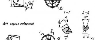
3. The design and main dimensions of the cutters must correspond to those indicated in the drawing. 1-4 and in table. 1-4.
Type 1
| With |
| r L |
Official publication Reproduction prohibited
N
Edition with Amendments No. 1, 2, approved in February 1981, June 1985.
(IUS 4-81, 9-85).
Table 1
mm
| Designation incisors | Apply bridge | Cutter section hb | L | T | Type of plates according to GOST 25398-90 | Thread pitch P |
| 2660-0001 | 16-10 | 100 | 1,5 | 0,5-2,5 | ||
| 2660-0003 | 20-12 | 120 | 3,0 | 11 | 0,8—3,0 | |
| 2660-0005 | 25-16 | 140 | 4,0 | 1,25-5 | ||
| 2660-0007 | 32-20 | 170 | 5,0 | 2-6 |
Note. Dimension g is made depending on the thread pitch (gish- = 0.144 S).
An example of a symbol for a cutter of type 1, with a cross-section hb = 20-12 mm, for a metric thread with a pitch P = 2 mm, with a plate made of hard alloy grade T15K6:
Cutter 2660-0003 2 T15K6 GOST 18885-73
T i p 2
| Designation incisors | Apply bridge | Cutter section hb | L | / | d | T | Type of plates according to GOST 25398-90 | Step thread P | D hiring |
| 2662-0001 | 10-10 | 120 | 40 | 10 | 4 | 11 | 0,75-2,50 | 18 | |
| 2662-0003 | 12-12 | 140 | 50 | 12 | 5 | 1-3 | 24 | ||
| 2662-0005 | 16-16 | 170 | 60 | 16 | 9 | 1,5-4 | 30 | ||
| 2662-0007 | 20-20 | 200 | 80 | 20 | 12 | 2-5 | 42 | ||
| 2662-0009 | 25-25 | 240 | 100 | 25 | 14 | 3-6 | 52 |
An example of a symbol for a cutter of type 2, with a cross-section hb = 20-20 mm, for a metric thread with a pitch P = 3.5 mm, with a plate made of hard alloy grade T15K6:
Cutter 2662-00073.5 T15K6 GOST 18885-73
Crap. 3
| Incisors | Cutter section h ■ b | L | T | Type plates | Step threads R | |
| for right-hand thread | for left-hand thread | |||||
| Designation | Apply bridge | Designation | Apply bridge | |||
| 2664-0001 | 2664-0002 | 20-12 | 120 | 2,0 | 48 according to GOST 25422-90 | 2 |
| 2664-0003 | 2664-0004 | 3 | ||||
| 2664-0005 | 2664-0006 | 3,0 | 4 | |||
| 2664-0007 | 2664-0008 | 5 | ||||
| 2664-0009 | 2664-0010 | 25-16 | 140 | 4,0 | 6 | |
| 2664-0011 | 2664-0012 | 8 | ||||
| 2664-0013 | 2664-0014 | 6,0 | 10 | |||
| 2664-0015 | 2664-0016 | 32-20 | 170 | 12 | ||
| 2664-0017 | 2664-0018 | 8,0 | 16 | |||
| 2664-0019 | 2664-0020 | 40-25 | 200 | 10,0 | 32 according to GOST 25412-90 | 20 |
| 2664-0021 | 2664-0022 | 12,5 | 24 |
An example of a symbol for a type 3 cutter, with a cross-section hb = 2516 mm, for a right-hand trapezoidal thread with a pitch P = 6 mm, with inserts made of hard alloy grade T15K6:
Cutter 2664-0009 6 T15K6GOST 18885- 73
Type 4
I
Table 4
Dimensions in mm
| Incisors | Cutter section h ■ b | L | / | d | T | Type of plates according to GOST 25422-90 | Step threads R | D hiring | |
| for right-hand thread | for left-hand thread | ||||||||
| Designation | Apply bridge | Designation | Apply bridge | ||||||
| 2666-0001 | 2666-0002 | 1010 | 120 | 40 | 10 | 4 | 48 | 2 | 16 |
| 2666-0003 | 2666-0004 | 4 | |||||||
| 2666-0005 | 2666-0006 | 1212 | 140 | 50 | 12 | 4 | 2 | 22 | |
| 2666-0007 | 2666-0008 | 6 | 5 | ||||||
| 2666-0009 | 2666-0010 | 7 | 8 | ||||||
| 2666-0011 | 2666-0012 | 1616 | 170 | 60 | 16 | 6 | 3 | 30 | |
| 2666-0013 | 2666-0014 | 8 | 6 | ||||||
| 2666-0015 | 2666-0016 | 10 | 10 | ||||||
| 2666-0017 | 2666-0018 | 20 20 | 200 | 80 | 20 | 8 | 3 | 44 | |
| 2666-0019 | 2666-0020 | 10 | 8 | ||||||
| 2666-0021 | 2666-0022 | 12 | 12 | ||||||
| 2666-0023 | 2666-0024 | 25-25 | 240 | 100 | 25 | 6 | 4 | 62 | |
| 2666-0025 | 2666-0026 | 10 | 10 | ||||||
| 2666-0027 | 2666-0028 | 15 | 6 |
An example of a symbol for a type 4 cutter, with a cross-section hb = 1010 mm, for a right-hand trapezoidal thread with a pitch P = 2 mm, with a T15K6 grade hard alloy insert:
Cutter 2666-0001-2 T15K6 GOST 18885-73 (Changed edition, Amendment No. 1,2).
4. The values of the radii of roundings and chamfers not specified in this standard are accepted for technological reasons.
5. Structural elements and geometric parameters of the cutters are indicated in the appendix.
6. The form of sharpening the front surface and finishing of the cutting part are specified in Appendix 2 to GOST 18877-73.
7. Technical requirements - according to GOST 5688-61.
Thread cutting using lathe equipment
When cutting a thread on a workpiece mounted on a lathe using a cutter, the process looks like this: the tool, moving along the axis of the rotating part (feed movement), draws a screw-type line on its surface with its pointed tip. A characteristic parameter of the helix formed by the cutter on the surface of the workpiece is the angle of its elevation or increase. The magnitude of this angle, measured between the tangent located to the helix and the plane, which is perpendicular to the axis of rotation of the part, is determined:
- the amount of feed of the cutting tool moving along the axis of the workpiece;
- the frequency at which the part rotates.
An equally important parameter of the helix is its pitch, which characterizes the distance between its adjacent turns. This distance is measured along the axis of the workpiece.
Moving along the axis of the rotating workpiece, the cutter cuts into it and creates a helical surface, which is commonly called a thread. Elements with a threaded surface are used to solve various problems: ensuring the movement of elements relative to each other, their articulation and sealing of the formed joints.
The most common types of thread profile: a - triangular, b - rectangular, c - trapezoidal, d - persistent, e - round
The surface of the threaded workpiece can be cylindrical or conical. The characteristics of a threaded connection are significantly influenced by the thread profile, that is, its plane contour. Profiles are distinguished:
- triangular;
- trapezoidal;
- rectangular;
- persistent;
- round.
The thread on the surface of the part can be formed by one screw thread (single-start) or several (multi-start). If several screw threads are cut, then they are placed equidistant in relation to each other.
You can count the number of threads at the beginning of the threaded surface. A multi-start thread, in addition to the pitch, is characterized by such a parameter as stroke. This is the distance measured between two similar points of two adjacent turns, which are formed by one thread. This distance is measured along a line parallel to the axis of the threaded part. For a single-start thread formed by one thread, the stroke is equal to the pitch, but for a multi-start thread it can be calculated by multiplying the pitch by the number of starts.
All types of threads with diagrams, parameters and GOST regulations regulating them
Manufacturing methods
It is important to know how to cut a trapezoidal thread in order to avoid malfunctions during its operation. Trapezoidal threads are easily produced on an industrial scale. Its manufacturing technique is similar to the production of rectangular carvings. The following cutting methods exist:
- From the use of 1 cutter. Before carrying out this procedure, it is important to prepare the workpiece for cutting: measure its length and width using a ruler or caliper. The product is placed on the lathe table. You need to make a groove in the workpiece into which the cutting tool will fit. When applying the cutter, it is worth checking the correctness of its location, placing it parallel to the thread axis. After completing the preparatory work, you can turn on the machine. During processing, the cutting edge of the tool makes a translational movement, forming a thread on the profile of the part. It is important to compare the processed part with the template after completing the work process. Their profiles must match. Due to the inaccuracy of the cutting tool, minor errors may occur.
- Use of 3 incisors. Before carrying out the procedure, preparatory work is also carried out: setting up a lathe, calculating the dimensional parameters of the product and setting up 3 cutters. Cutting tools are applied to the grooves of the workpiece and checked for secure fastening. According to the diameter and helix angle of the product, the tapping cutters can be installed parallel to the sides of the helical groove and opposite to the thread axis. 3 cutters perform translational movements, forming the final profile. Verification of processing accuracy is carried out by comparing the resulting part with a template.
When creating screw structures, a different cutting method is used. An incomplete groove is made using a cutter. After this, you need to select a smaller cutting tool and increase the length of the groove to the internal diameter. The procedure is completed with a profile cutter. The processing result is checked using nominal and limit calibers.
During cutting, it is important to follow basic safety rules when working with cutting devices and lathes:
- Work with tools must be carried out by a specialist with appropriate instructions.
- Person The worker is required to have a special uniform, consisting of a work coat, safety glasses with clear lenses, a hat, boots and gloves. Overalls must be repaired and clean. Before working with tools, it is important to ensure that the suit is fully buttoned and fits snugly to the body.
- No foreign objects should be placed in the workplace.
- Before sharpening, it is important to check the condition of the lathe. It must contain mechanisms for removing production waste, tubes and hoses for cooling, and shields for reflecting the emulsion. The lathe should be checked at idle speed, assessing the performance of its main components.
- There should be no chips or foreign objects on the lathe chuck.
- During processing, it is important to check the strength of the cutting tools and the location of the workpiece.
- You cannot secure a workpiece weighing more than 16 kg and take measurements while it is rotating.
- It is necessary to promptly remove industrial waste using special chip removal devices.
- To cut parts made of ductile metals, special cutting tools with sharpening are used.
- While processing workpieces, it is forbidden to lean on the machine, lubricate parts, support the product with your hands, or get rid of chips using a stream of air.
- When turning, it is necessary to use steady rests if processing is carried out at high speed.
- It is important to monitor the drainage of coolant from the lathe.
- Do not leave the machine while it is in use.
In the event of fires at work, it is necessary to turn off the machine equipment, move to a safe distance and notify the competent authorities. Compliance with safety precautions will reduce the risk of emergency situations.
Cutting tool - die
A die is a cutting turning tool made in the shape of a nut. The holes drilled in it are made to remove chips. The tool consists of cutting elements located on each side and forming a fence cone. A die on a lathe forms threads on bolts, studs, screws and other metal products.
The most used types of dies:
- metric;
- left;
- pipe
Thread cutting with a die should be preceded by processing the desired area of the part. In this case, the outer cross-section of the thread must be larger than the machined area of the part. The difficulty of cutting a thread with a die is that it does not have a special lead, which makes it difficult to cut the initial turns smoothly.
You can make the task easier by making a small chamfer at the end so that its height coincides with the height of the thread profile. The size of the die must match the diameter of the part.
Then the die of the required size is fixed in a die holder fixed in the tailstock of the lathe. The thread cutting speed depends on the material for the workpiece: brass products are processed at about 15 m/min, cast iron - 3 m/min, steel blanks - 4 m/min.
At this processing speed, the die wears less. During the cutting process, each rotation of the die must be replaced by turning it back a third of the circle to clear the holes from chips.
