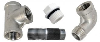
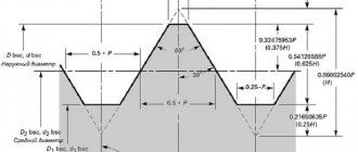
Unified inch thread UNF (Unified National Fine) is a national American thread with a fine pitch and a profile angle of 60°. This thread is a modification of the 55° BSW (British Standard Witworth) thread, also known as a Whitworth thread. Inch threads are based on the inch measurement system, while in Russia the metric system is adopted, for this reason many questions arise related to the definition and search for such fasteners on the Russian market. UNF inch thread is common in the USA, Canada, and Great Britain. UNF thread geometry and form are regulated by ASME B1.1-2003 (The American Society of Mechanical Engineers).
A distinctive feature of inch threads is the designation of diameter and length in fractions of an inch. The English inch is used as a basis, equal to 25.4 mm. Such sizes are indicated by inch, in or double stroke “. In this case, the size will be indicated in fractions of an inch, for example 1″ or ½”. The thread pitch of an inch fastener refers to the number of threads on a 1-inch length, for example 1″ - 12 UNF. In this case, the number of threads per inch may not be indicated, since in the UNF thread standard, each thread diameter has a certain number of turns. Then the thread designation could be 1″ UNF. Small thread diameters, less than 1/4″, are designated by a conventional number from 0 to 12 and the symbol No. or # is added, for example # 4 – 48 UNF.
Characteristics of inch thread
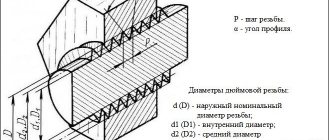
The main parameters of inch threads are diameter and pitch.
There are internal and external diameters. The internal diameter is defined as the distance between the lowest points of the recesses between the threaded ridges, which are on opposite sides of the part. The outer diameter of an inch thread is defined as the distance between the top points of the ridges, which are on opposite sides of the part. The difference between the outer and inner diameter determines the height of the thread profile.
The pitch of an inch thread is the distance between two adjacent valleys or crests. For a thread to work, the pitch must be constant along the entire length of the cut thread.
Standard sizes are given in the table of parameters of inch threads with diameters and pitch:
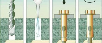
Making threads
The procedure and rules for cutting it according to the American UNF standard do not differ from the cutting method using the metric system. The only difference is the use of special tools and methods for setting up the machine. As for metric connections, manual or mechanical thread cutting is used. Both methods are applicable for cutting internal and external threads.
The basic rules that must be followed when cutting are:
- selection of the required drill diameter;
- preliminary selection of diameter (it must be equal to the diameter minus the pitch).
These data are provided in reference tables. If such tables are missing, the calculation must be done independently.
At enterprises engaged in the mass production of parts that use inch American cylindrical threads of this standard, mechanical cutting methods are used. This operation is performed using the following equipment:
- lathes equipped with special taps;
- threading machines capable of producing external and internal cutting;
- screw-cutting lathes equipped with numerical control.
The third type of machines is equipped with special programs that allow you to cut the entire list of UNF.
Marking
The designation of the thread in question includes a letter indicating the type (UNC) and a digital index indicating the diameter (in inches). In some cases, additional notations are used. They can reflect step (via a dash) and direction. For small options (less than 1/4''), special markings are used. This is due to their difficulty in measuring. Designations include numbers (from 0 to 12) and the frequency of turns (through a dash). For example, you can consider 1/4” – 20UNСх2 1/2”.
- 1/4 – diameter (in this case, the outer value is 6.35 mm, the inner value is 5.35 mm).
- 20 – frequency of turns.
- UNC - typ.
- 2 1/2'' is the length of the bolt.
Dimensions
ANSI B1.1 uses nominal diameter to designate UNC thread options. However, the connection parameters more accurately reflect the values of the outer and inner diameters. The frequency of turns is inversely related to the pitch and diameter.
The nominal diameter for UNC threads is up to 4''. The outer and inner diameters range from 1.854 and 1.5 to 101.6 and 96.5 mm. The thread frequency ranges from 64 to 4 per inch with a pitch of 0.397 to 6.35 mm. The entire list of options is indicated in the standard table.
Pipe thread
A separate standard group that regulates the connection of pipes using different wall materials. Inch pipe threads are divided into types:
- cylindrical type;
- conical view;
- NPSM thread.
Straight pipe thread
Also known as Whitward carving. It is used for cylindrical connections using threads and for joining a cylindrical internal thread with an external conical pipe.
The designation of the shape profile is an inch thread with a profile in the form of a triangle with equal hips and an angle at the top of 55º. It is allowed to connect pipes with a maximum diameter of 6 inches, and for pipes larger than an inch size, a connection by welding is used.
Tapered inch pipe thread
It is cut on the surface of pipes for conical connection of pipes and for connecting cylindrical threads on the inside and tapered threads on the outside. The use of sealed gaskets is mandatory; the sealing role is partially played by the thread. The profile is designated as an inch type with a taper; the letter expression of the index indicates its location. R indicates external thread, Rc indicates internal thread, and the letters LH are used for left-hand threads.
Thread profile type NPSM
This thread cutting is done in accordance with American pipe thread standards and is similar in location and type to cylindrical inch threads. Defined by a profile shape in the form of a triangle with an apex of 60º and is produced in sizes from 1/16 to 24 inches.
This type should not be confused with the American subtype NPT, which is a standard inch-threaded conical connection for pipes with increased reliability requirements when working with high pressure and in difficult operating conditions.
Differences between pipe and metric threads
There are not many of them; the most noticeable indicator that distinguishes one type from another is the shape of the threaded ridge cutting profile. In appearance it seems sharper, its apex angle is 55º.
In addition to the profile shape, the difference between metric cutting and the inch pipe version is the measuring parameters of pitch and diameter. Metric threads are measured in millimeters, while imperial threads are measured in inches. But to express metric indicators in inches, a non-standard value of 2.54 cm is used, and a special pipe inch equal to 3.324 cm.
A detailed table indicating the corresponding conversions from inches to millimeters can be found in the specified GOST. In addition to whole inch values, fractional values are also indicated. In addition, the pitch is not counted in millimeters, but in threads, indicating cut grooves on a measured inch segment.
The step is determined using working tools:
- combs;
- calibers;
- mechanical meters.
Measurements are made according to the same rules in metric and inch cutting. To begin with, we use a coupling or fitting with a cut external or internal thread, starting from known parameters. Screw the bolt into the thread and determine the tightness of the fit. If the bolt fits tightly, then the pitch and diameter are considered certain. If the bolt does not match, then try using a bolt of a different caliber.
It is more convenient to use a thread gauge, then the work happens faster - just attach the plate to the thread. The number of the thread is indicated on the tool plate, which is considered defined if the profiles match. A caliper or micrometer is used only to determine the outer and inner diameters.
American UNC thread
International standards for fastening connections: UNC Unified Coarse Thread (UNC) is a type of inch cylindrical thread with a large pitch and a profile angle of 60°.
It is very popular in Europe and North America.
In Russia, parts with left- and right-hand UNC threads can be found among components for foreign-made household and industrial equipment (lawn mowers, cultivators, cars, etc.).
Contact phone number: WhatsApp.
Brief history Inch carving appeared in Great Britain during the Industrial Revolution in the 18th century.
Since a significant part of the North American continent was for a long time in the zone of direct influence of the United Kingdom, the English system of measures took root in Canada and the United States.
After unification, certain standards for thread cutting were developed: profile angle, pitch, shape of peaks and valleys, etc. This is how basic standard sizes and principles for marking connections arose, which are still used today.
Technical features Externally, the geometry of the UNC thread is not much different from the profile of a conventional metric thread. The main feature of the connection is the use of the inch as the main dimensional unit.
The maximum pitch is 6.35 mm (4 threads per inch).
How are UNC threads cut? The most difficult thing when cutting inch threads is to correctly determine the pitch size. To do this, you need to use special gauges (thread gauges).
When measuring the distance between the valleys and the peaks, the thread gauge plates are applied to the part one by one until 100% coincidence of the profile is achieved.
If the size was determined correctly, the thread pitch will correspond to the value marked on the side of the template.
Two types of tools are used for cutting UNC threads:
- dies. Required for external threading; - taps. Used to form threads on the inside of a part.
Threads can be cut either manually or using special industrial equipment. The direction of rotation is determined individually in each case.
Accuracy classes and marking rules
A thread belonging to the inch type, as indicated by GOST, can correspond to one of three accuracy classes - 1, 2 and 3. Next to the number indicating the accuracy class, put the letters “A” (external) or “B” (internal). The full designations of thread accuracy classes, depending on its type, look like 1A, 2A and 3A (for external) and 1B, 2B and 3B (for internal). It should be borne in mind that class 1 corresponds to the coarsest threads, and class 3 corresponds to the most precise threads, the dimensions of which are subject to very stringent requirements.
Maximum size deviations according to GOST
To understand what parameters a specific threaded element corresponds to, it is enough to understand the designation of the thread that is applied to it. The designation in question is used by many foreign manufacturers who work according to American standards relating to elements of threaded connections.
An example of a symbol for an inch thread
This marking contains the following information about the thread:
- nominal size (outer diameter) – first digits;
- number of turns per inch of length;
- group;
- accuracy class.
General information, markings
NPT pipe threads are available in two configurations - external and internal. A pipe fitting with such a thread has the shape of a narrowed cone; due to this structure, increased strength of the connection between two pipeline elements is ensured.
The conical standard is practically not used in water supply systems, since in this case its safety margin is excessive. The main areas of application for NPT are mechanical engineering, machine tools, oil and gas industries, and this connection is also widely used in hydraulic systems.
To connect two pipes, a conical thread is formed on the fittings of each of them, with an internal cone cut on one and an external cone on the other. The angle of inclination of the cone is unified and amounts to 3034'49”, which is equal to the taper (C)1:16.
There are two types of tapered thread dimensions - inch and metric, depending on which the nomenclature designation of NPT connections in diagrams and drawings differs. If one of the sides of the pipe or fitting on which the cone is cut is metric, the abbreviation NPT-E is used, but if both sides of the cones being connected are inch, the additional abbreviation is not used and simply NPT is indicated.
Appearance of tapered NPT thread
Specifications for NPT thread sizes and configurations are given in the following international standards:
- ANSI/ASME B36.10M;
- BS 1600, 10255;
- DIN 2999.
There are also domestic regulatory documents for conical connections:
- GOST No. 6111-52 “Inch conical thread with a profile angle of 60 degrees”;
- GOST No. 6211-81 “Basic standards of interchangeability - conical pipe threads.”
Today, specialized stores offer a wide number of adapters and adapters that have a cylindrical thread on one side and a conical thread on the other, which allows you to easily use pipes with American standard fittings.
Designation principles
The designation of threads in drawings is carried out according to the following rules.
- Indicate with solid thin and thick lines. The designation of an internal thread is a thin line along the outer diameter and a thick line on the internal one, and an external thread is indicated by a thick line along the outer diameter and a thin line on the internal one.
- If the part is projected onto a plane along the axis of rotation, then it is shown as solid straight lines. If - across, then this is an open contour, 0.75 of the total circumference. The ends of the arc should not lie on the axes of the part in the figure.
- The gap between the thin and thick lines should be more than 0.8 mm, but less than the step size.
- When designating metric threads in drawings perpendicular to the axis, chamfers are depicted only with structural significance.
External and internal thread types
Metric threads are standardized by several documents: GOST 8724-2004, GOST 2470-2004, GOST 9150-2002, GOST 1693-2005. They specify the requirements for dimensions, profile, pitches and tolerances.
Based on the product labeling, you can determine all the necessary parameters and type. Entry includes:
- a capital letter characterizing the type, or two capital letters - a type and a subspecies (for example, metric - M; metric conical - MK);
- a number expressing the nominal diameter in millimeters (M20 - metric with a nominal diameter of 20 mm);
- in the case of a small step, indicate its value in millimeters, using the multiplication sign - M20x1.5;
- in the case of a multi-start, add an indication of the stroke after the “x” and the step in parentheses - M20x3(P1) - metric with a diameter of 20 mm, three-start, where the step is 1 mm;
- when designating a left-hand thread, the Latin capital letters “LH” are written - M20LH or M20x3(P1)LH - also only left-handed.
In some cases, the marking may include additional parameters: make-up length, tolerances and fit. Their decoding is as follows:
- indication of tolerance for external thread M12x1.75-6g and for internal thread M12-6N;
- make-up length is expressed in capital Latin letters - S - shot (short), N - normal (normal), L - long (long), sometimes a numerical value of the length in millimeters is added in parentheses if the value is non-standard; for example, M12-6g-L(30);
- the fit is expressed as a fraction through the tolerance values for internal (numerator) and external (denominator) threads, for example, taking into account how left-hand threads are designated, the general appearance will be M12x1-6H/6g-LH.
The marking may also indicate the type and number of the standard.
By choosing the right type of metric thread and its geometric parameters, you can ensure high-quality fastening of parts, long-term operation of the product and savings on repairs and maintenance.
Cutting technology
UNC threads are created by removing a portion of material from the surfaces of cylindrical and tapered workpieces. This is done on machines. Depending on the type, taps and dies are used (for internal and external, respectively).
The shank is used for installation in the driver or chuck of the machine. The working part is divided into intake and calibrating. The first carries out cutting, the second serves for calibration. The cutting edges are formed by longitudinal grooves, which also provide chip exit. The cutting parts limited by grooves are called cutting feathers.
On machine tools, machine options are most often used, however, for hard and viscous materials, specific sets of taps are required, including two or three tools. They differ in the purity of processing and perform different amounts of work. So, for a set of two taps the proportion is 75/25%, for a set of three – 60/30/10%. Structurally, the taps of one set differ in the length of the intake part, which is the longest in the draft version. For workpieces with a surface interrupted by a groove or groove, tools with a number of grooves not a multiple of the number of grooves and with helical grooves are used. The latter are also suitable for holes with a length of two diameters or more. In this case, the direction of the screw groove must correspond to the thread being cut. Specific options are represented by grooveless taps. They are designed to create short through threads. Such tools are more durable and have better quality of work. Another specific version of taps is with staggered teeth, designed for short through threads on tough materials. They reduce friction, improve coolant flow and chip formation. Taps are installed similarly to dies or in cartridges for them. The speed of work is 5-12 for steel and 6-22 m/s for other materials. When cutting, cooling with oil or emulsion is required.
Due to the different configurations on the machines, they are mounted in different holders. Thus, for lerks, lerk holders are used, represented by cranks in the form of frames with 2 handles. The die is located inside and is fixed with three screws that go into the recesses on its sides. The frames for sliding options are made in the form of oblique frames with 2 handles. Half dies are placed in the hole, adjusting the size with a pressure screw.
Before cutting the thread, the surface of the workpiece is treated. For an external connection, it is necessary to ensure a smaller diameter in relation to the outer diameter of the thread. This difference is approximately 0.1-0.3 mm depending on the size of the connection. At the end, a chamfer corresponding to the height of the profile is removed to form an approach. The die is mounted with a holder in the socket of the head or tailstock quill. The speed of work is determined by the type of material. So, for steel blanks it is 3-4, for cast iron - 2-3, for brass - 10-15 m/min.
Slicing technologies
Cylindrical pipe threads, which are of the inch type (both internal and external), can be cut manually or mechanically.
Manual thread cutting
Cutting a thread using a hand tool, which uses a tap (for internal) or a die (for external), is performed in several steps.
- The pipe being processed is clamped in a vice, and the tool used is fixed in a driver (tap) or in a die holder (die).
- The die is put on the end of the pipe, and the tap is inserted into the inside of the latter.
- The tool used is screwed into the pipe or screwed onto its end by rotating a driver or die holder.
- To make the result cleaner and more precise, you can repeat the cutting procedure several times.
Thread cutting on a lathe
Mechanically, pipe threads are cut according to the following algorithm:
- The pipe being processed is clamped in the machine chuck, on the support of which a thread-cutting tool is fixed.
- At the end of the pipe, using a cutter, a chamfer is removed, after which the speed of movement of the caliper is adjusted.
- After bringing the cutter to the surface of the pipe, the machine turns on the threaded feed.
It should be borne in mind that inch threads are cut mechanically using a lathe only on tubular products whose thickness and rigidity allow this to be done. Making pipe inch threads mechanically allows you to obtain a high-quality result, but the use of such technology requires the turner to have the appropriate qualifications and certain skills.
What are inch taps and inch threads?
A tap is perhaps the most common tool for cutting internal threads, which is used everywhere. Threads are cut in new products both by machine and by hand, and worn ones are also restored.
Very often, the use of inch taps is associated with the restoration of threads when repairing equipment, since a large amount of equipment used today in our country is produced according to European or American standards.
To understand what inch taps are, you need to understand what the inch thread is for which they are intended.
The concept of inch, in contrast to metric, includes a fairly large number of different threads that have different pitches and profile angles.
Therefore, to select the right tap, you need to know several determining parameters. All inch threads are designated by a diameter in inches (fraction), as well as a pitch in threads (turns) per 1 inch.
And parts or tools are not always marked with the type to which they belong. This is what causes confusion.
First of all, there are 5 standards that specify the parameters of all the most frequently used ones:
- DIN ISO 228 (also DIN 2999, DIN 259 GOST 6357-81) - determines the parameters of cylindrical inch pipe threads. The profile angle is 55°. It has only four pitch values - 11, 14, 19 and 28 threads per inch. Designated G (less commonly Rp), and also corresponds to BSP (British Standard Pipe) threads.
- BS 84 (formerly DIN 11) - defines the parameters of British Standard BSW (Ww) and BSF threads, Whitworth threads and fine pitch threads respectively. The profile angle is 55°.
- ANSI/ASME B 1.1 is an American standard that defines threads of the unified family: UNC, UNF, UN, UNEF, UNS. The profile angle is 60°, the same as the metric one. The most common are UNC and UNF, with coarse and fine pitches respectively. For example, a 1/4" thread with 20 threads per inch is UNC, and a 1/4" thread with 28 threads per inch is UNF. UNEF is a thread with an especially fine pitch.
- ANSI B.1.20.1 (also GOST 6111-52) is a standard for tapered pipe threads, which in the American standard is designated NPT (taper 1:16). The profile angle is 60°. In GOST 6111-52 it is designated by the letter K - conical inch. The American standard also describes cylindrical pipe NPS.
- DIN 40 430 is also a standard for pipe threads, designated PG. It practically never happens here.
As you can see, it is quite easy to get confused in so many designations, so you need to be careful when ordering a tool. If possible, you need to check the thread with a gauge or consult with specialists.
As a rule, for the same diameter in inches, each thread has its own pitch, so you can determine from the catalog what type it is. The most common ones are: G, UNC and UNF.
The rest are quite rare, but they also need to be kept in mind.
Can you supply inch fasteners with small diameters?
GOST R 50864-96 conical locking thread for drill string elements. profile, dimensions, technical requirements
These dimensions start from #1 (1.854 mm)
up to #12 (5.436mm)
TK Hardware company can supply it to order for you.
The lead time for these items will be approximately 4-6 weeks
.
The average minimum packaging for such diameters is 200 pieces.
Fasteners with small diameters can be presented in the form of screws with a semicircular head (the so-called computer screws with inch threads), with a countersunk head, with a cylindrical head, in the form of bolts with a hexagonal head, as well as nuts and washers for them. The material in which they can be made is from black (without coating or black) to non-ferrous and stainless metal.
Basic rules for slicing
- To correctly cut inch or metric threads, you must adhere to the following recommendations:
- Accurately select a drill of the required diameter. The hole diameters for UNF and UNC threads are shown in the tables above.
- Drill a hole strictly at right angles to the plane.
- Carry out cutting in a reciprocating motion. After two forward revolutions, make a backward revolution to remove chips.
- If there are two or three taps in the set, pass strictly by numbers - first with the first draft number, then with the second.
- It is advisable to use a lubricant to reduce friction.
Differences between UNF and UNC threads
Apart from the 60° profile angle, UNF and UNC cylindrical threads have no similarities. Due to differences in tolerance values and designations, they are not interchangeable.
The distinctive features and advantages of UNF threads include:
- smaller helix angle, providing better tightness and promoting self-locking of the thread;
- resistance to significant breaking loads due to the small thread depth and larger contact area of the turns;
- better loss prevention effect;
- more teeth on threads of the same length, which reduces the likelihood of fluid leakage.
Features and differences of American carving
The most popular thread in the USA and Canada is the inch cylindrical thread UNF/UTS (Unified Thread Standard). It is also called American carving. Its 60˚ tip angle and profile height are fully consistent with metric threads, but all thread sizes are based on the inch measurement system. They are indicated in fractions of an inch.
Based on the pitch, American inch threads come in several types:
- with a large step UNC (Unified Coarse);
- fine pitch UNF (Unified Fine);
- fine thread for special applications UNEF (Unified Extra Fine);
- specialized inch cylindrical thread UNS (Unified Special), which is one of the types of UTS (Unified Thread Standard) threads.
Peculiarities
The peculiarity of this thread is determined based on the following parameters:
- geometric parameters;
- size (number of threads per inch);
- cutting direction;
- required drill diameter;
- accuracy class;
- application area.
All types of UNF threads belong to the fine category. It can be thought of as metric 60 degrees. A distinctive feature is the unit of measurement - this is an inch. That's why it's called inch thread or American thread. Each small carving has its own distinctive dimensions. Its analogue is the English BSW thread sizes, which are located in special tables
Specific features can be identified by markings. It consists of the following elements:
- in the first place is the abbreviation UNF (literally translated means “Unified Group of Small Threads”);
- Next comes the size in inches;
- completes the marking of the step value.
Accuracy classes and marking rules
A thread belonging to the inch type, as indicated by GOST, can correspond to one of three accuracy classes - 1, 2 and 3. Next to the number indicating the accuracy class, put the letters “A” (external) or “B” (internal). The full designations of thread accuracy classes, depending on its type, look like 1A, 2A and 3A (for external) and 1B, 2B and 3B (for internal). It should be borne in mind that class 1 corresponds to the coarsest threads, and class 3 corresponds to the most precise threads, the dimensions of which are subject to very stringent requirements.
Maximum size deviations according to GOST
To understand what parameters a specific threaded element corresponds to, it is enough to understand the designation of the thread that is applied to it. The designation in question is used by many foreign manufacturers who work according to American standards relating to elements of threaded connections.
An example of a symbol for an inch thread
This marking contains the following information about the thread:
- nominal size (outer diameter) – first digits;
- number of turns per inch of length;
- group;
- accuracy class.
If you have a question, how to determine the type and size of thread Connecting fittings for pipes and hoses
connections use the table below.
Please note the following:
- connections with inch threads are highlighted in color
- next to the inch step size in tpi the step size in mm is indicated
- connections with external tapered threads usually do not have a threaded groove
- BSPT and NPT conical fittings are very similar, but BSPT has a mark on the hexagon
An important note - situations are quite possible when the inch and metric pitches are very close in size (this is possible on JIC connections).
Read also: Scraper conveyor operating principle
In this case, it is possible to confuse the inch thread. American cylindrical inch thread UNF (Unified Thread Standard)
UNC UNF and metric threads.
Threaded fasteners are one of the most popular for attaching parts, assembling products, equipment, and structures. There is no industry where it is not used. There are many thread characteristics: pitch, tolerance range, number of starts, nominal diameter, profile type and others. One of these is units of measurement, inches or millimeters.
There is often a situation when it is necessary to replace a bolt, pin or screw, but the fastener purchased for maximum similarity “by eye” is not screwed into the mounting hole. One of the reasons is an attempt to screw a fastener with an external inch thread into a hole with a metric thread. Or vice versa. This situation often arises when replacing fasteners on products or equipment manufactured in the UK, USA, Japan, or Australia. There, inch threads have priority.
How to distinguish an inch thread from a metric thread? There are two main ways - by measuring the pitch and diameter or using a special tool.
Measurement
Fastener thread markings are done differently in metric and inch systems. In metric, this is an indication of the thread pitch (the distance between adjacent threads) in millimeters, while in inch it is the number of threads per inch.
Determining the type and size of fastener thread comes down to the following operations. Use a caliper to measure the diameter. Then, using an inch ruler or caliper, measure the number of threads in one inch and the thread pitch. You can also use a regular ruler with measured 2.54 mm (1 inch = 2.54 mm). The metric thread pitch on small fasteners can be found by measuring the distance between 10 turns and dividing the resulting value by 10. The resulting values should be compared with the table below. The maximum match in diameter, number of turns, pitch indicates the size and type of thread. It should be noted that there are many different types of inch threads. The table shows the most common ones in the diameter range from 8 mm to 64 mm.
You can also use a thread gauge to measure threads. This is its direct purpose. A thread gauge is a set of plates with protruding teeth for a specific thread, united on a single axis. The thread size is engraved or permanently inked on the plate itself. Checking the thread is done by applying plates that are closest in size to the thread. If there is a complete match, without gaps, the thread can be considered defined, and its size can be viewed on the thread gauge plate. Thread gauges are produced separately for metric, inch threads or both types.
What is the difference between an inch thread and a metric thread?
The structural difference between an inch thread and a metric thread is that the ridges are sharper: they are located at an angle of 55° to each other, while for a metric thread the angle between the ridges is 60°.
Thanks to sharper ridge angles, inch threads provide improved connection quality. Due to this, the interface unit can better withstand variable loads and high pressure, which is of great importance when installing pipelines. In some cases, inch threads are used in the manufacture of screws, bolts and other hardware, in the production of parts for certain types of equipment (for example, they are widely used in cameras).
To determine the parameters of different types of threads, different units of measurement are used. Metric uses millimeters and inches uses inches. Inch thread sizes are indicated in fractional and integer numbers. The pitch of an inch thread in tables can be indicated in threads - the number of turns cut into one inch of length.
You can determine the corresponding main dimensions of metric and inch threads of different types using special tables. An example of such a table:
Application of UNF thread
Fine threads are not suitable for use under high dynamic loads and high tensile stresses - they are used for positioning, adjustment, fixing, etc. Threads with fine pitches are more difficult to loosen, so UNF is used in connections that require sealing and are subject to vibration.
UNF thread is used for fastening thin-walled parts of measuring instruments, for example, lenses of optical instruments, micrometer elements, battery compartment covers, etc. Thin threads have a small height and require careful handling to avoid damage affecting the quality of the assembly.
At EMK you can buy products with UNF ANSI / ASME B1.1 threads. We work directly with manufacturing plants and provide comprehensive supplies of metal products throughout the CIS. Products undergo quality control and have certificates of compliance with standard requirements. You can order UNF threaded fasteners by phone or through the website.
Inch thread table. Classification
An inch thread is a thread, all parameters of which are expressed in inches, the thread pitch is in fractions of an inch (inch = 2.54 cm). For inch pipe threads, the size in inches characterizes the clearance in the pipe, and the outer diameter of the pipe itself is slightly larger.
Inch threads are used in threaded connections and screw drives. Inch threads come in the following types:
- Inch cylindrical – UTS (Unified Thread Standard). This type of carving is widespread in the USA and Canada. The apex angle of this thread is 60 degrees. Depending on the step, it is divided into: UNC (Unified Coarse); UNF (Unified Fine); UNEF (Unified Extra Fine); 8UN; UNS (Unified Special). The most widely used thread is UNC. This thread conforms to ANSI 1 standard.
- British standard inch thread - BSW. Fine pitch threads are called BSF (British Standard Fine). The apex angle of this thread is 55 degrees.
- Inch tapered NPT or cylindrical NPS. Meets ANSI/ASME 20.1. This thread is used for pipe connections. Has an apex angle of 60 degrees. In Russia, such threads correspond to GOST 6111-52.
Most often in Russia recently you can find fasteners with inch UNC threads (unified coarse thread).
Such fasteners are often found on equipment imported into our country (lawn mowers, trimmers, generators, cultivators, American-made cars, etc.) from the USA, China and some other countries.
When working with inch fasteners, you must remember that the sizes of the keys for inch fasteners are different from the keys for metric fasteners.
The main dimensions of inch UNC fasteners are given in the table of inch threads
| N 1 – 64 UNC | 0,073 | 1,854 | 1,50 | 64 | 0,397 |
| N 2 – 56 UNC | 0,086 | 2,184 | 1,80 | 56 | 0,453 |
| N 3 – 48 UNC | 0,099 | 2,515 | 2,10 | 48 | 0,529 |
| N 4 – 40 UNC | 0,112 | 2,845 | 2,35 | 40 | 0,635 |
| N 5 – 40 UNC | 0,125 | 3,175 | 2,65 | 40 | 0,635 |
| N 6 – 32 UNC | 0,138 | 3,505 | 2,85 | 32 | 0,794 |
| N 8 – 32 UNC | 0,164 | 4,166 | 3,50 | 32 | 0,794 |
| N 10 – 24 UNC | 0,190 | 4,826 | 4,00 | 24 | 1,058 |
| N 12 – 24 UNC | 0,216 | 5,486 | 4,65 | 24 | 1,058 |
| 1/4″ – 20 UNC | 0,250 | 6,350 | 5,35 | 20 | 1,270 |
| 5/16″ – 18 UNC | 0,313 | 7,938 | 6,80 | 18 | 1,411 |
| 3/8″ – 16 UNC | 0,375 | 9,525 | 8,25 | 16 | 1,587 |
| 7/16″ – 14 UNC | 0,438 | 11,112 | 9,65 | 14 | 1,814 |
| 1/2″ – 13 UNC | 0,500 | 12,700 | 11,15 | 13 | 1,954 |
| 9/16″ – 12 UNC | 0,563 | 14,288 | 12,60 | 12 | 2,117 |
| 5/8″ – 11 UNC | 0,625 | 15,875 | 14,05 | 11 | 2,309 |
| 3/4″ – 10 UNC | 0,750 | 19,050 | 17,00 | 10 | 2,540 |
| 7/8″ – 9 UNC | 0,875 | 22,225 | 20,00 | 9 | 2,822 |
| 1″ – 8 UNC | 1,000 | 25,400 | 22,25 | 8 | 3,175 |
| 1 1/8″ – 7 UNC | 1,125 | 28,575 | 25,65 | 7 | 3,628 |
| 1 1/4″ – 7 UNC | 1,250 | 31,750 | 28,85 | 7 | 3,628 |
| 1 3/8″ – 6 UNC | 1,375 | 34,925 | 31,55 | 6 | 4,233 |
| 1 1/2″ – 6 UNC | 1,500 | 38,100 | 34,70 | 6 | 4,233 |
| 1 3/4″ – 5 UNC | 1,750 | 44,450 | 40,40 | 5 | 5,080 |
| 2″ – 4 1/2 UNC | 2,000 | 50,800 | 46,30 | 4,5 | 5,644 |
| 2 1/4″ – 4 1/2 UNC | 2,250 | 57,150 | 52,65 | 4,5 | 5,644 |
| 2 1/2″ – 4 UNC | 2,500 | 63,500 | 58,50 | 4 | 6,350 |
| 2 3/4″ – 4 UNC | 2,750 | 69,850 | 64,75 | 4 | 6,350 |
| 3″ – 4 UNC | 3,000 | 76,200 | 71,10 | 4 | 6,350 |
| 3 1/4″ – 4 UNC | 3,250 | 82,550 | 77,45 | 4 | 6,350 |
| 3 1/2″ – 4 UNC | 3,500 | 88,900 | 83,80 | 4 | 6,350 |
| 3 3/4″ – 4 UNC | 3,750 | 95,250 | 90,15 | 4 | 6,350 |
| 4″ – 4 UNC | 4,000 | 101,600 | 96,50 | 4 | 6,350 |
Tightening torques
Tightening torques for UNC inch fasteners for SAE grade 5 and higher bolts and nuts are shown in the following table.
| 1/4 | 12± 3 | 9±2 |
| 5/16 | 25 ± 6 | 18± 4,5 |
| 3/8 | 47± 9 | 35 ± 7 |
| 7/16 | 70± 15 | 50± 11 |
| 1/2 | 105± 20 | 75±15 |
| 9/16 | 160 ± 30 | 120± 20 |
| 5/8 | 215± 40 | 160 ± 30 |
| 3/4 | 370 ± 50 | 275 ± 37 |
| 7/8 | 620± 80 | 460 ± 60 |
| 1 | 900 ± 100 | 660 ± 75 |
| 11/8 | 1300 ± 150 | 950 ± 100 |
| 1 1/4 | 1800 ±200 | 1325 ±150 |
| 1 3/8 | 2400 ± 300 | 1800 ± 225 |
| 1 1/2 | 3100 ± 350 | 2300 ± 250 |
*1 Newton meter (N*m) is equal to approximately 0.1 kgm.** Pound-force foot is the British and US equivalent of N*m.
Marking of inch fasteners
Inch fasteners have a more complex marking system that does not allow visually, without the use of special tables, to determine the mechanical properties of the fastener. The most common markings on the heads of inch bolts and their correspondence to strength classes are shown in the table below.
| 1 or 2 | 6.8 |
| 5 | 8.8 |
| 6 | 10.9 |
NPT/NPTF tapered thread: main characteristics and standards
Appearance of a tapered NPT thread NPT/NPTF (national pipe taper/national pipe tapered fuel) thread is an American standard for tapered pipe threads. This standard applies to pipes and fittings that are manufactured in the USA.
NPT tapered pipe thread complies with GOST 6111-52 “Inch tapered thread with a profile angle of 60 degrees”, which is valid in most CIS countries.
The United States National Hydraulic Transmission Association advises against the use of NPT and NPTF standards in hydraulics. But despite this, the use of these standards is very widespread.
NPT thread diagram
Types of inch threads:
- NPT – thread with a taper of 1:16 and a profile angle of 60°. This thread complies with ANSI B1.21.1, FED-STD-H28/7 standards.
- NPS – cylindrical thread.
- NPTF - sealed inch thread with a profile angle of 60°, sealing occurs due to thread compression. This type of inch thread complies with SAE J476, ANSI B1.20.3, FED-STD-H28/8 standards.
Main parameters of the most common NPTF threaded connections:
| Nominal diameter, inch | Main diameter, mm | Threaded hole, mm | Threads per inch | Pitch, mm |
| NPTF 1/16″ | 7.870 | 6.00 | 27 | 0.940 |
| NPTF 1/8″ | 10.217 | 8.25 | 27 | 0.940 |
| NPTF 1/4″ | 13.577 | 10.70 | 18 | 1.411 |
| NPTF 3/8″ | 17.016 | 14.10 | 18 | 1.411 |
| NPTF 1/2″ | 21.211 | 17.40 | 14 | 1.814 |
| NPTF 3/4″ | 26.566 | 22.60 | 14 | 1.814 |
| NPTF 1″ | 33.195 | 28.50 | 11.5 | 2.209 |
| NPTF 1 1/4″ | 41.952 | 37.00 | 11.5 | 2.209 |
| NPTF 1 1/2″ | 48.021 | 43.50 | 11.5 | 2.209 |
| NPTF 2″ | 60.060 | 55.00 | 11.5 | 2.209 |
| NPTF 2 1/2″ | 72.642 | 65.50 | 8 | 3.175 |
| NPTF 4″ | 113.913 | 107.00 | 8 | 3.175 |
Main parameters of the most common NPT threaded connections:
| Nominal diameter, inch | Main diameter, mm | Threaded hole, mm | Threads per inch | Pitch, mm |
| NPT 1/16″ | 7.870 | 6.00 | 27 | 0.940 |
| NPT 1/8″ | 10.217 | 8.25 | 27 | 0.940 |
| NPT 1/4″ | 13.577 | 10.70 | 18 | 1.411 |
| NPT 3/8″ | 17.016 | 14.10 | 18 | 1.411 |
| NPT 1/2″ | 21.211 | 17.40 | 14 | 1.814 |
| NPT 3/4″ | 26.566 | 22.60 | 14 | 1.814 |
| NPT 1″ | 33.195 | 28.50 | 11.5 | 2.209 |
| NPT 1 1/4″ | 41.952 | 37.00 | 11.5 | 2.209 |
| NPT 1 1/2″ | 48.021 | 43.50 | 11.5 | 2.209 |
| NPT 2″ | 60.060 | 55.00 | 11.5 | 2.209 |
| NPT 2 1/2″ | 72.642 | 65.50 | 8 | 3.175 |
| NPT 4″ | 113.913 | 107.00 | 8 | 3.175 |
| NPT 5″ | 141,300 | 134,384 | 8 | 3.175 |
| NPT 6″ | 168,275 | 161,191 | 8 | 3.175 |
| NPT 8″ | 219,075 | 211,673 | 8 | 3.175 |
| NPT 10″ | 273,050 | 265,311 | 8 | 3.175 |
| NPT 12″ | 323,850 | 315,793 | 8 | 3.175 |
To create an NPT (NPTF) connection, special threading machines with a tap (die or threading head) are used.
ProfInst Stroy brings to your attention equipment with which you can cut NPT (NPTF) threads on pipes and workpieces with high quality:
- Die heads from 1/2 to 2 inches. Designed for high-quality, high-performance thread cutting. Safe and quick replacement.
- Manual threading dies from 1/2 to 1.1/4 inches. Designed for cutting conical pipe threads on water, electrical or gas pipes. It has high performance and is easy to transport.
- Manual threading dies from 1/2 to 2 inches. Can be widely used in equipment installation and construction industry, ideal for increasing labor productivity, reducing construction time, ensuring its quality, and reducing labor intensity.
- Electric threading machines from 1/2 to 2 inches. High-performance threading machine for mobile and stationary use. Suitable for long-term, intensive use in the workshop and on the construction site, used in the installation of heating and water supply systems and in mass production. The machine cuts precise threads of very high quality.
- Electric threading machines from 1/2 to 3 inches. The machine is designed for cutting screw and cylindrical threads on pipes. Used to produce precise, reliable threaded connections on pipes and bolts in accordance with codes. It is designed for long-term industrial use.
- Electric threading machines from 1/2 to 4 inches. The machine is designed for cutting pipe and metric threads. Used for the manufacture of precise, reliable threaded connections on pipes and studs in accordance with standards.
NPT threads are used in connections with increased tightness requirements. Connections with such threads are able to withstand strong pressure of the circulating medium through the pipeline.
To buy equipment for cutting NPT (NPTF) conical threads on pipes, contact ProfInst Stroy managers by contact numbers: +375 (17) 256-22-55, +375 (29) 602-00-80, +375 (29) 766-07-00, we will tell you in detail about the operating features, design and specifics of this type of equipment.
Tool design
The UNF/UNC tap is a screw with flutes and corresponding sharpening of the front, back and other corners. The main elements of the tool are the cutting (taking) and calibrating parts, grooves for removing chips. The cutting part is made of high-speed steel or hard alloy. A suitable shank is available for manual use or installation in a chuck.
The advantage of the tool is the simplicity and manufacturability of the design, as well as high cutting accuracy and the ability to work due to self-feeding. The difficulty is the need to apply large cutting forces and friction forces, and difficulties in removing chips.
Depending on the design, UNF/UNC taps are divided into:
- manual or metalworking;
- machine-manual;
- machine;
- nuts and others.
Designation principles
To determine the main qualities, you need to understand its designation. The thread designation in the drawings is slightly different from those used by the manufacturer in the production of products. Thread tables allow you to determine the main characteristics only by designation.
The features of the marking include the following points:
- Symbol for the thread in question G.
- The diameter size is indicated after the letter. An example of notation is 1 ½.
- The symbol L indicates that the turns are left-handed.
- The next symbol H indicates the accuracy class.
- The make-up length is represented by numbers at the end of the marking.
The designation of a tapered thread in the drawing provides an indication of the accuracy class. A symbol indicating the accuracy class may be indicated in the technical documentation. The creation of turns is carried out in compliance with one of three classes. In addition, the letters “A” and “B” may be indicated next to the number: the first indicates an external indicator, the second internal. The first class corresponds to the coarsest threads, the third is the highest quality.
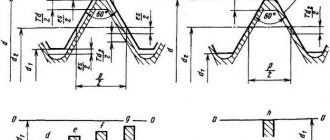
Tapered pipe threads
drawing of pipe tapered threads
Tapered pipe thread GOST 6211-81 (1st standard size)
Parameter Unit: Inch
Fits a rounded 55° straight pipe thread profile. See the top part (I) of the 3D image "drawing of pipe tapered threads".
Symbol
International: R
Japan: PT
UK: BSPT
The letter R and the nominal diameter Dy are indicated. The designation R means external thread, Rc internal, Rp internal cylindrical. By analogy with cylindrical pipe threads, LH is used for left-hand threads.
Examples:
R1 ½ - external pipe thread, nominal diameter Dy = 1 ½ inches.
R1 ½ LH - external pipe thread conical, nominal diameter Dy = 1 ½ inches, left.
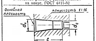
Conical inch thread GOST 6111 - 52 (2nd standard size)
Parameter Unit: Inch
Produced on surfaces with a taper of 1:16
Has a profile angle of 60°. See the bottom part (II) of the 3D image "drawing of pipe tapered threads". It is used in pipelines (fuel, water, air) of machines and machines with relatively low pressure. The use of this type of connection assumes tightness and locking of the thread without additional special means (linen threads, yarn with red lead).
Symbol
The first letter is K, then GOST.
Example:K ½ GOST 6111 - 52
It stands for: inch conical thread with an outer and inner diameter in the main plane approximately equal to the outer and inner Ø of a cylindrical pipe thread G ½
Table of main parameters of tapered inch threads
| Thread size designation (d, inches) | Number of threads per 1″ n | Thread pitch S, mm | Thread length, mm | Outer thread diameter in the main plane d, mm | |
| Working l1 | From the end of the pipe to the main plane l2 | ||||
| 1/16 | 27 | 0,941 | 6,5 | 4,064 | 7,895 |
| 1/8 | 27 | 0,941 | 7,0 | 4,572 | 10,272 |
| 1/4 | 18 | 1,411 | 9,5 | 5,080 | 13,572 |
| 3/8 | 18 | 1,411 | 10,5 | 6,096 | 17,055 |
| 1/2 | 14 | 1,814 | 13,5 | 8,128 | 21 793 |
| 3/4 | 14 | 1,814 | 14,0 | 8,611 | 26,568 |
| 1 | 11 1/2 | 2,209 | 17,5 | 10,160 | 33,228 |
| 1 1/4 | 11 1/2 | 2,209 | 18,0 | 10,668 | 41,985 |
| 1 1/2 | 11 1/2 | 2,209 | 18,5 | 10,668 | 48,054 |
| 2 | 11 1/2 | 2,209 | 19,0 | 11,074 | 60,092 |
American thread with extra fine pitch – UNEF
| Thread size | Threads per inch | D - outer diameter | Dp - average diameter | Di - internal diameter | Thread pitch | |
| inches | mm | millimeters | ||||
| #12 | 5,49 | 32 | 5,49 | 4,97 | 4,63 | 0,79 |
| 1/4 | 6,35 | 32 | 6,35 | 5,83 | 5,49 | 0,79 |
| 5/16 | 7,94 | 32 | 7,94 | 7,42 | 7,08 | 0,79 |
| 3/8 | 9,53 | 32 | 9,53 | 9,01 | 8,67 | 0,79 |
| 7/16 | 11,1 | 28 | 11,11 | 10,52 | 10,13 | 0,91 |
| 1/2 | 12,7 | 28 | 12,70 | 12,11 | 11,72 | 0,91 |
| 9/16 | 14,3 | 24 | 14,29 | 13,60 | 13,14 | 1,06 |
| 5/8 | 15,9 | 24 | 15,88 | 15,19 | 14,73 | 1,06 |
| 11/16 | 17,5 | 24 | 17,46 | 16,77 | 16,32 | 1,06 |
| 3/4 | 19,1 | 20 | 19,05 | 18,22 | 17,68 | 1,27 |
| 13/16 | 20,6 | 20 | 20,64 | 19,81 | 19,26 | 1,27 |
| 7/8 | 22,2 | 20 | 22,23 | 21,40 | 20,85 | 1,27 |
| 15/16 | 23,8 | 20 | 23,81 | 22,99 | 22,44 | 1,27 |
| 7/16 | 11,1 | 20 | 11,11 | 10,29 | 9,74 | 1,27 |
| 1 | 25,4 | 20 | 25,40 | 24,57 | 24,03 | 1,27 |
| 1 1/16 | 26,9 | 18 | 26,99 | 26,07 | 25,46 | 1,41 |
| 1 1/8 | 28,6 | 18 | 28,58 | 27,66 | 27,05 | 1,41 |
| 1 3/16 | 30,2 | 18 | 30,16 | 29,25 | 28,64 | 1,41 |
| 1 1/4 | 31,8 | 18 | 31,75 | 30,83 | 30,22 | 1,41 |
| 1 5/16 | 33,3 | 18 | 33,40 | 32,42 | 31,81 | 1,41 |
| 1 3/8 | 34,9 | 18 | 34,93 | 34,01 | 33,40 | 1,41 |
| 1 7/16 | 36,5 | 18 | 36,51 | 35,60 | 34,99 | 1,41 |
| 1 1/2 | 38,1 | 18 | 38,10 | 37,18 | 36,57 | 1,41 |
| 1 9/16 | 39,7 | 18 | 39,69 | 38,77 | 38,16 | 1,41 |
| 1 5/8 | 41,3 | 18 | 41,27 | 40,36 | 39,75 | 1,41 |
| 1 11/16 | 42,9 | 18 | 42,86 | 41,95 | 41,34 | 1,41 |
How to deal with American inch thread?
Metric fasteners are marked so that the type and mechanical properties of the fastening material can be identified. The head of the bolt according to DIN 931 is marked with 8.8. This means that the bolt is made of carbon steel. The strength class determines the value of the maximum permissible operating loads that the fastener can withstand. Inch fasteners are marked more difficult. To understand the system of its marking, special tables are used. With their help, you can find out the mechanical properties of the fastener and the grade of material. To understand how to convert an American inch thread to the metric system, you need to use a caliper to measure the outer diameter of the thread (in mm), the inner diameter and the pitch of the thread (measured in the number of threads per inch). Measurements must be made with an accuracy of tenths and hundredths of a millimeter. After this, you need to use reference tables for inch threads and select a match for the resulting combination for a particular inch fastener.
Tightening torques
Tightening torques for UNC inch fasteners for SAE grade 5 and higher bolts and nuts are shown in the following table.
| Thread size, inches | Tightening torque for standard bolts and nuts | |
| N*m* | Pound-force-foot** | |
| 1/4 | 12± 3 | 9±2 |
| 5/16 | 25 ± 6 | 18± 4,5 |
| 3/8 | 47± 9 | 35 ± 7 |
| 7/16 | 70± 15 | 50± 11 |
| 1/2 | 105± 20 | 75±15 |
| 9/16 | 160 ± 30 | 120± 20 |
| 5/8 | 215± 40 | 160 ± 30 |
| 3/4 | 370 ± 50 | 275 ± 37 |
| 7/8 | 620± 80 | 460 ± 60 |
| 1 | 900 ± 100 | 660 ± 75 |
| 11/8 | 1300 ± 150 | 950 ± 100 |
| 1 1/4 | 1800 ±200 | 1325 ±150 |
| 1 3/8 | 2400 ± 300 | 1800 ± 225 |
| 1 1/2 | 3100 ± 350 | 2300 ± 250 |
*1 Newton meter (N*m) is equal to approximately 0.1 kgm.** Pound-force foot is the British and US equivalent of N*m.
How to deal with American inch thread?
Metric fasteners are marked so that the type and mechanical properties of the fastening material can be identified. The head of the bolt according to DIN 931 is marked with 8.8. This means that the bolt is made of carbon steel. The strength class determines the value of the maximum permissible operating loads that the fastener can withstand. Inch fasteners are marked more difficult. To understand the system of its marking, special tables are used. With their help, you can find out the mechanical properties of the fastener and the grade of material. To understand how to convert an American inch thread to the metric system, you need to use a caliper to measure the outer diameter of the thread (in mm), the inner diameter and the pitch of the thread (measured in the number of threads per inch). Measurements must be made with an accuracy of tenths and hundredths of a millimeter. After this, you need to use reference tables for inch threads and select a match for the resulting combination for a particular inch fastener.
Production: video
We have already talked about two cutting methods. Now let’s take a look at one of them, which you can do yourself at home:
In the article we wrote about conical and cylindrical inch threads. We provided tables, as well as calculation methods, talked about the features (parameters) of choice, and even gave a short historical summary. We hope this information was useful to you. To conclude, there is a video:
After you read the article, you can read about our products. for 15 years on the Russian market. During this time, we covered almost all cities of the country.