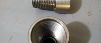
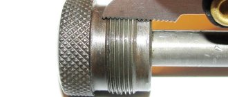
Trapezoidal threads are widely used to make various screws that are used for various production equipment. For example, for machines, lifting devices, presses. This thread has the form of an isosceles trapezoid, and the profile angle can have different values: 15, 24, 30, 40°. During the operation of a screw on which a trapezoidal thread is cut, frictional forces appear naturally caused. That is, due to the presence of lubricant, surface roughness, and profile angle.
Types of thread
Today there are the following types:
- Metric. It serves to secure several elements. The cutting conditions are established in the regulatory documentation. The profile is a triangle with equilateral angles. This indicator is 60°. Screws with metric threads are made in small and large pitches. The first type is used to secure thin-sheet elements to create increased tightness. This type of connection can be found in precision optical instruments.
- Conical. It is manufactured in the same way as the previous type, but twisting is done to a depth of 0.8 mm.
- Inch. To date, there is no regulatory document that would indicate thread sizes. Inch threads are used in the repair of various equipment. As a rule, these are old instruments and devices. Its main indicators are the outer diameter and pitch.
- Pipe cylindrical. This type is an isosceles triangle, the upper angle of which is 55°. This internal thread is used to connect pipelines, as well as parts made of thin sheet material. It is recommended when there are special requirements for the tightness of the connection.
- Pipe conical. The internal thread must comply with all regulatory requirements. The sizes are completely standardized. It is used to connect various types of pipelines.
- Persistent. This type is an unequal trapezoid, where one side is inclined by 3° and the other by 30°. The first side is the working side. The shape of the profile, as well as the diameter of the steps, are determined by regulatory documents. In accordance with them, threads are made with a diameter from 10 to 600 mm, with a maximum pitch value of 24 mm. They are used where increased holding forces are required.
- Round. The thread profile consists of various arcs connected by straight lines. The profile angle is 30°. This type of thread is used for those connections that are exposed to aggressive environments.
- Rectangular. It is not supported by any regulatory documents. Its main advantage is high efficiency. Compared to the trapezoidal type, it is less durable, and also causes many incomprehensible moments during its production. The main place of application is jacks and various types of screws.
- Trapezoidal. It has the shape of an isosceles trapezoid with a profile angle of 30°. Trapezoidal threads, the dimensions of which are fixed in the documentation, are used to connect various elements of production equipment.
TOLERANCES
The numerical values of the tolerances for the diameters of external and internal threads must correspond to those indicated in the table. 3 – 5.
Table 3
Diameter tolerances d
and
D
1
| Step R , mm | External thread | Internal thread | Step R , mm | External thread | Internal thread | ||
| Degree of accuracy | Degree of accuracy | ||||||
| 4 | 6 | 4 | 4 | 6 | 4 | ||
| Tolerance, µm | Tolerance, µm | ||||||
| Td | Td | ||||||
| 1,5 | 150 | 236 | 190 | 16 | 710 | – | 1000 |
| 2 | 180 | 280 | 236 | 18 | 800 | – | 1120 |
| 3 | 236 | 375 | 315 | 20 | 850 | – | 1180 |
| 4 | 300 | 475 | 375 | 22 | 900 | – | 1250 |
| 5 | 335 | 530 | 450 | 24 | 950 | – | 1320 |
| 6 | 375 | 600 | 500 | 28 | 1060 | – | 1500 |
| 7 | 425 | 670 | 560 | 32 | 1120 | – | 1600 |
| 8 | 450 | 710 | 630 | 36 | 1250 | – | 1800 |
| 9 | 500 | 800 | 670 | 40 | 1320 | – | 1900 |
| 10 | 530 | 850 | 710 | 44 | 1400 | – | 2000 |
| 12 | 600 | 950 | 800 | 48 | 1500 | – | 2120 |
| 14 | 670 | – | 900 |
Table 4
Diameter tolerances d
2 and
D
2
| Nominal thread diameter d , mm | Step P , mm | External thread | Internal thread | ||||||
| Degree of accuracy | |||||||||
| 6 | 7 | 8 | 9 | 6 | 7 | 8 | 9 | ||
| Tolerance, µm | |||||||||
| St. 5.6 to 11.2 | 1,5 | 132 | 170 | 212 | 265 | 180 | 224 | 280 | 355 |
| 2 | 150 | 190 | 236 | 300 | 200 | 250 | 315 | 400 | |
| 3 | 170 | 212 | 265 | 335 | 224 | 280 | 355 | 450 | |
| St. 11.2 to 22.4 | 2 | 160 | 200 | 250 | 315 | 212 | 265 | 335 | 425 |
| 3 | 180 | 224 | 280 | 355 | 236 | 300 | 375 | 475 | |
| 4 | 212 | 265 | 335 | 425 | 280 | 355 | 450 | 560 | |
| 5 | 224 | 280 | 355 | 450 | 300 | 375 | 475 | 600 | |
| 8 | 280 | 355 | 450 | 560 | 375 | 475 | 600 | 750 | |
| St. 22.4 to 45 | 2 | 170 | 212 | 265 | 335 | 224 | 280 | 355 | 450 |
| 3 | 200 | 250 | 315 | 400 | 265 | 335 | 425 | 530 | |
| 5 | 236 | 300 | 375 | 475 | 315 | 400 | 500 | 630 | |
| 6 | 265 | 335 | 425 | 530 | 355 | 450 | 560 | 710 | |
| 7 | 280 | 355 | 450 | 560 | 375 | 475 | 600 | 750 | |
| 8 | 300 | 375 | 475 | 600 | 400 | 500 | 630 | 800 | |
| 10 | 315 | 400 | 500 | 630 | 425 | 530 | 670 | 850 | |
| 12 | 335 | 425 | 530 | 670 | 450 | 560 | 710 | 900 | |
| St. 45 to 90 | 3 | 212 | 265 | 335 | 425 | 280 | 355 | 450 | 560 |
| 4 | 236 | 300 | 375 | 475 | 315 | 400 | 500 | 630 | |
| 5 | 250 | 315 | 400 | 500 | 335 | 425 | 530 | 670 | |
| 8 | 315 | 400 | 500 | 630 | 425 | 530 | 670 | 850 | |
| 9 | 335 | 425 | 530 | 670 | 450 | 560 | 710 | 900 | |
| 10 | 335 | 425 | 530 | 670 | 450 | 560 | 710 | 900 | |
| 12 | 375 | 475 | 600 | 750 | 500 | 630 | 800 | 1000 | |
| 14 | 400 | 500 | 630 | 800 | 530 | 670 | 850 | 1060 | |
| 16 | 425 | 530 | 670 | 850 | 560 | 710 | 900 | 1120 | |
| 18 | 450 | 560 | 710 | 900 | 600 | 750 | 950 | 1180 | |
| 20 | 450 | 560 | 710 | 900 | 600 | 750 | 950 | 1180 | |
| St. 90 to 180 | 4 | 250 | 315 | 400 | 500 | 335 | 425 | 530 | 670 |
| 5 | 280 | 355 | 450 | 560 | 375 | 475 | 600 | 750 | |
| 6 | 300 | 375 | 475 | 600 | 400 | 500 | 630 | 800 | |
| 8 | 335 | 425 | 530 | 670 | 450 | 560 | 710 | 900 | |
| 12 | 400 | 500 | 630 | 800 | 530 | 670 | 850 | 1060 | |
| 14 | 425 | 530 | 670 | 850 | 560 | 710 | 900 | 1120 | |
| 16 | 450 | 560 | 710 | 900 | 600 | 750 | 950 | 1180 | |
| 18 | 475 | 600 | 750 | 950 | 630 | 800 | 1000 | 1250 | |
| St. 90 to 180 | 20 | 475 | 600 | 750 | 950 | 630 | 800 | 1000 | 1250 |
| 22 | 500 | 630 | 800 | 1000 | 670 | 850 | 1060 | 1320 | |
| 24 | 530 | 670 | 850 | 1060 | 710 | 900 | 1120 | 1400 | |
| 28 | 560 | 710 | 900 | 1120 | 750 | 950 | 1180 | 1500 | |
| 32 | 600 | 750 | 950 | 1180 | 800 | 1000 | 1250 | 1600 | |
| St. 180 to 355 | 8 | 355 | 450 | 560 | 710 | 475 | 600 | 750 | 950 |
| 10 | 400 | 500 | 630 | 800 | 530 | 670 | 850 | 1060 | |
| 12 | 425 | 530 | 670 | 850 | 560 | 710 | 900 | 1120 | |
| 18 | 500 | 630 | 800 | 1000 | 670 | 850 | 1060 | 1320 | |
| 20 | 530 | 670 | 850 | 1060 | 710 | 900 | 1120 | 1400 | |
| 22 | 530 | 670 | 850 | 1060 | 710 | 900 | 1120 | 1400 | |
| 24 | 560 | 710 | 900 | 1120 | 750 | 950 | 1180 | 1500 | |
| 32 | 530 | 800 | 1000 | 1250 | 850 | 1060 | 1320 | 1700 | |
| 36 | 670 | 850 | 1060 | 1320 | 900 | 1120 | 1400 | 1800 | |
| 40 | 670 | 850 | 1060 | 1320 | 900 | 1120 | 1400 | 1800 | |
| 44 | 710 | 900 | 1120 | 1400 | 950 | 1180 | 1500 | 1900 | |
| 48 | 750 | 950 | 1180 | 1500 | 1000 | 1250 | 1600 | 2000 | |
| St. 355 to 640 | 12 | 450 | 560 | 710 | 900 | 600 | 750 | 950 | 1180 |
| 16 | 500 | 630 | 800 | 1000 | 670 | 850 | 1060 | 1320 | |
| 20 | 560 | 710 | 900 | 1120 | 750 | 950 | 1180 | 1500 | |
| 24 | 600 | 750 | 950 | 1180 | 850 | 1060 | 1320 | 1700 | |
| 48 | 800 | 1000 | 1250 | 1600 | 1060 | 1320 | 1700 | 2120 |
Table 5
Diameter tolerances d
3
| Nominal thread diameter d , mm | Step R , mm | Main diameter deviation d 2 | ||||||
| With | e | g | ||||||
| Degree of accuracy | ||||||||
| 8 | 9 | 6 | 7 | 8 | 6 | 7 | ||
| Tolerance, µm | ||||||||
| St. 5.6 to 11.2 | 1,5 | 405 | 471 | 232 | 279 | 332 | 197 | 245 |
| 2 | 445 | 525 | 259 | 309 | 366 | 226 | 276 | |
| 3 | 501 | 589 | 298 | 350 | 416 | 261 | 313 | |
| St. 11.2 to 22.4 | 2 | 462 | 544 | 271 | 321 | 383 | 238 | 288 |
| 3 | 520 | 614 | 310 | 365 | 435 | 273 | 328 | |
| 4 | 609 | 721 | 360 | 426 | 514 | 325 | 391 | |
| 5 | 656 | 775 | 386 | 456 | 550 | 351 | 421 | |
| 8 | 828 | 965 | 482 | 576 | 695 | 435 | 529 | |
| St. 22.4 to 45 | 2 | 481 | 569 | 284 | 336 | 402 | 251 | 303 |
| 3 | 564 | 670 | 335 | 397 | 479 | 298 | 361 | |
| 5 | 681 | 806 | 401 | 481 | 575 | 366 | 446 | |
| 6 | 767 | 899 | 449 | 537 | 649 | 411 | 499 | |
| 7 | 813 | 950 | 475 | 569 | 688 | 433 | 527 | |
| 8 | 859 | 1015 | 507 | 601 | 726 | 460 | 554 | |
| 10 | 925 | 1087 | 544 | 650 | 775 | 490 | 596 | |
| 12 | 998 | 1173 | 589 | 701 | 833 | 534 | 646 | |
| St. 45 to 90 | 3 | 589 | 701 | 350 | 116 | 504 | 313 | 379 |
| 4 | 659 | 784 | 390 | 470 | 564 | 355 | 435 | |
| 5 | 712 | 837 | 419 | 500 | 606 | 384 | 465 | |
| 8 | 890 | 1052 | 526 | 632 | 757 | 479 | 585 | |
| 9 | 943 | 1118 | 559 | 671 | 803 | 509 | 621 | |
| 10 | 963 | 1138 | 569 | 681 | 813 | 515 | 627 | |
| 12 | 1085 | 1273 | 639 | 764 | 920 | 584 | 709 | |
| 14 | 1142 | 1355 | 680 | 805 | 967 | 620 | 745 | |
| 16 | 1213 | 1438 | 721 | 853 | 1028 | 661 | 793 | |
| 18 | 1288 | 1525 | 763 | 900 | 1088 | 703 | 840 | |
| 20 | 1313 | 1550 | 775 | 912 | 1100 | 708 | 845 | |
| St. 90 to 180 | 4 | 690 | 815 | 408 | 489 | 595 | 373 | 454 |
| 5 | 775 | 912 | 456 | 550 | 669 | 421 | 515 | |
| 6 | 830 | 986 | 493 | 587 | 712 | 455 | 549 | |
| 8 | 928 | 1103 | 551 | 663 | 795 | 504 | 616 | |
| 12 | 1122 | 1335 | 670 | 795 | 958 | 615 | 740 | |
| 14 | 1193 | 1418 | 711 | 843 | 1018 | 651 | 783 | |
| St. 90 to 180 | 16 | 1263 | 1500 | 753 | 890 | 1078 | 693 | 830 |
| 18 | 1338 | 1588 | 794 | 950 | 1138 | 734 | 890 | |
| 20 | 1363 | 1613 | 806 | 962 | 1150 | 739 | 895 | |
| 22 | 1450 | 1700 | 849 | 1011 | 1224 | 780 | 943 | |
| 24 | 1538 | 1800 | 899 | 1074 | 1299 | 828 | 1003 | |
| 28 | 1625 | 1900 | 950 | 1138 | 1375 | 880 | 1068 | |
| 32 | 1718 | 2005 | 1015 | 1203 | 1453 | 945 | 1133 | |
| St. 180 to 355 | 8 | 965 | 1153 | 576 | 695 | 832 | 529 | 648 |
| 10 | 1088 | 1300 | 650 | 775 | 938 | 596 | 721 | |
| 12 | 1173 | 1398 | 701 | 833 | 1008 | 646 | 778 | |
| 18 | 1400 | 1650 | 825 | 987 | 1200 | 765 | 928 | |
| 20 | 1488 | 1750 | 875 | 1050 | 1275 | 808 | 983 | |
| 22 | 1513 | 1775 | 887 | 1062 | 1287 | 818 | 993 | |
| 24 | 1600 | 1875 | 936 | 1124 | 1361 | 865 | 1053 | |
| 32 | 1780 | 2092 | 1053 | 1265 | 1515 | 983 | 1195 | |
| 36 | 1885 | 2210 | 1118 | 1343 | 1605 | 1048 | 1273 | |
| 40 | 1925 | 2250 | 1138 | 1363 | 1625 | 1063 | 1288 | |
| 44 | 2030 | 2380 | 1203 | 1440 | 1715 | 1128 | 1365 | |
| 48 | 2145 | 2545 | 1273 | 1523 | 1810 | 1188 | 1438 | |
| St. 355 to 640 | 12 | 1223 | 1460 | 733 | 870 | 1058 | 678 | 815 |
| 16 | 1375 | 1625 | 815 | 978 | 1190 | 755 | 918 | |
| 20 | 1550 | 1825 | 912 | 1100 | 1337 | 845 | 1033 | |
| 24 | 1663 | 1950 | 986 | 1174 | 1424 | 915 | 1103 | |
| 48 | 2233 | 2670 | 1335 | 1585 | 1898 | 1250 | 1500 |
Manufacturing conditions
Compared to other types, trapezoidal threads are much easier to manufacture.
That is why it is more often used in various fields. The most popular is the trapezoidal thread screw, which has a profile angle of 30°. The production technology is very similar to that used for cutting rectangular threads. But there are still significant differences regarding the accuracy and cleanliness of manufacturing. Cutting a trapezoidal thread is no different from the same procedure with a rectangular thread. At the moment, there are several such methods.
Application
Previously, threads with a rectangular cross-section were used primarily in the manufacture of screw mechanisms. Now this type of cutting is used very rarely due to the technological difficulties that arise during the creation of a threaded connection, and the large number of gaps that appear between the screw turns during wear. Nowadays, this type of cutting has been completely replaced by trapezoidal thread. In it, gaps are eliminated by tightening the split nut.
Threads with a rectangular cross-section continue to be used in the industrial sector for the manufacture of fasteners, adjusting tools and connections, where it is necessary to reduce the self-loosening of power elements to a minimum value. The following devices are produced using rectangular cutting technology:
- A bolt is a cylindrical rod with a head. According to GOST 7798-70, this fastener is manufactured in 3 versions, differing in the location of the holes. The dimensions of the rod and bolt head must correspond to the length of the diameter of the threaded connection. Most often, right-angle bolts are made with a hex head.
- Studs are cylindrical rods, at both ends of which there is a thread with a square profile. Used to connect various devices and parts. An example of a stud designation: M300´1.6-6g´110.59, where the diameter of the product, its pitch, tolerance range, length and strength class are indicated accordingly. Studs are used in cases where it is impossible to connect parts using bolts, which is due to the high thickness of the product.
- Screws are a cylindrical rod with a head and thread. These devices differ from bolts by having recesses for screwdrivers and other tools. They are used to secure parts during assembly or repair procedures. There are 3 types of screw structures: installation, regulating and fastening. According to GOST No. 1491-80 and GOST No. 17474-80, screws must be manufactured with a cylindrical or semi-countersunk head. Square profile threads are used in the manufacture of lead screws or weight screws.
- Nuts are parts that are screwed onto bolts or studs. They have threaded holes and are characterized by height parameters: low, medium, high and especially high.
- Washers are stamped rings placed under nuts or heads of fastening tools. They can be made with or without a chamfer. GOST 11371-78 establishes the parameters of thickness, length, material and coating for washers.
The limited use of threads with a rectangular profile is due to the impossibility of eliminating its main disadvantages. It cannot be milled or sanded. For this reason, this type of cutting is very difficult to create on an industrial scale. The main application area for rectangular threads is in the mechanical engineering and instrument making sectors, where fastening devices (bolts, nuts, washers, studs and screws) are often used.
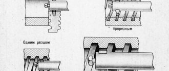
Making a screw with one cutter
Single-start trapezoidal threads are manufactured as follows:
- the workpiece is prepared and channels for sharpening are created;
- The cutter is sharpened according to a special prepared template;
- The sharpened element is installed and secured. It should be positioned so that the centers coincide and are parallel to the cutting axis;
- the equipment is turned on and the workpiece is fed for thread cutting;
- the finished part is checked in accordance with the finished template.
Common production method
It is in production that cutting trapezoidal threads takes place in this way:
- working equipment is checked and adjusted;
- thanks to the slotted cutter, small indentations are made on the screw;
- using a narrow slotted element, the screw is cut to a certain diameter;
- with the help of a profile slotted element, the final production of trapezoidal threads is carried out;
- the finished part is checked in accordance with ready-made templates.
Cutting process
Before you start cutting, you should use drills to make a hole in the workpiece. The diameter of the drill hole must match the internal thread size. When the size of the hole made with drills is chosen incorrectly, the tool can break or the grooves will turn out to be of poor quality.
For example, when cutting M5 (groove diameter is 5 mm), you should choose a drill for a 4.2 mm hole. To cut M4, the diameter of the drill must be 3.3 millimeters, and before working with an M6 tap, a hole is first made with a 5 mm drill. This indicator is calculated taking into account the thread pitch. The pitch can be calculated mathematically, but in practice they resort to correspondence tables, where for an M5 tap the pitch is 0.8, for M4 this figure is 0.7, for M6 - 1. We subtract the pitch index from the diameter and get the required diameter of the drill. When working with brittle metals, such as cast iron, the drill diameter should be reduced by 0.1 mm compared to the size recommended in the table.
The formula for calculating the hole diameter when working with three-pass taps:
here: Dm is the diameter of the tap.
| Type | Diameter | Step |
| M1 | 0,75 | 0,25 |
| M1,2 | 0,95 | 0,25 |
| 1,4 | 1,1 | 0,3 |
| 1,7 | 1,3 | 0,36 |
| 2,6 | 1,6 | 0,4 |
| 2,8 | 1,9 | 0,4 |
| M3 | 2,1 | 0,46 |
| M3 | 2,5 | 0,5 |
| M4 | 3,3 | 0,7 |
| M5 | 4,1 | 0,8 |
| M6 | 4,9 | 1 |
| M8 | 6,7 | 1,25 |
| M10 | 8,4 | 1,5 |
Table 1. Correspondence between thread diameters and preparation hole
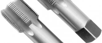
Before starting work, the tap is inserted into a square shank - a knob. The collars can be regular or ratchet. The carving is carried out carefully, the first pass is made with a tap No. 1 to the end
Particular attention must be paid to the direction of movement: only clockwise, and some effort must be applied. It is done like this: 12 turns along the stroke alternate with 14 turns against the screw stroke to destroy the chips
| Thread in inches | External D, mm | Diameter, mm | Pitch, mm |
| 18″ | 2,095 | 0,74 | 1,058 |
| 14″ | 6,35 | 4,72 | 1,27 |
| 316″ | 4,762 | 3,47 | 1,058 |
| 516″ | 7,938 | 6,13 | 1,411 |
| 716″ | 11,112 | 8,79 | 1,814 |
| 38″ | 9,525 | 7,49 | 1,588 |
Table 2. Hole diameters for inch threads
Trapezoidal thread: dimensions
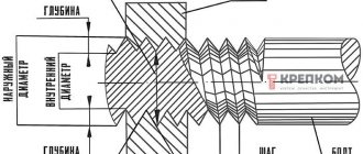
As mentioned earlier, this type of thread has the shape of a trapezoid, in which the angle between the sides can have different values. All main dimensions are set in accordance with GOST.
For a single-start type, trapezoidal threads (dimensions - GOST 9481-81) have dimensions and pitches of various diameters - from 10 to 640 mm. In addition, it can be multi-pass, as well as twisted to the left or right side. These indicators are standardized by GOST 24738-81.
Sides of trapezoid
The paired sides of trapezoids have their own names:
- The bases of a trapezoid are the sides that are located on parallel lines.
- Lateral - sides that are not on parallel lines.
Let's illustrate this with a picture:
In this case, sides AB and CD are parallel to each other. This means that they are the foundations. But AC and BD, on the contrary, are clearly not parallel. And accordingly, these are the sides.
By the way, the location of the sides does not depend on the location of the figure itself. Even in such situations
anyway, parallel sides will be considered bases, and non-parallel sides will be considered lateral.
Features of multi-start thread
To provide the screw with strength characteristics and increase its stroke, multi-start trapezoidal threads are used. In this case, all parameters, such as the height of the thread, its diameter, are absolutely the same, with a single-start appearance. The only difference is the number of moves per step. For example, three-start threads have a stroke three times their pitch. All this can be seen in the pictures.
Let us give an example so that this type becomes clear to every person. Everyone uses regular lids for canning vegetables and fruits. To open them you need to make a minimum of effort. When using large diameter cylinders, it is much more difficult to get into the grooves of a single-thread thread. That is why multi-pass ones are used.
This type of carving can be determined visually, just look at the drawing.
You can see exactly how many turns go from the beginning of the screw. Multi-pass threads are manufactured using complex technologies and, accordingly, are more expensive.
Quality control
To ensure that the workpiece has been processed correctly, it is necessary to use thread templates.
With their help, the thread pitch is checked. But for a comprehensive assessment, a thread gauge is used. For convenience, it is installed in a rack and adjusted according to a standard or template, then the movement of the part itself is checked.
You can also use the simplest and most commonly used method. Take a nut or bolt and scroll it over the completed part.
If scuffing is noticeable on the thread as you move, or more effort needs to be applied, then you have made an error in your work. Now you already know how to use a lathe to make various nuts, bolts or threaded connections.
It is important to remember that such parts require great care and tenderness with each pass, and even quality control. It’s better to spend more time on work than to ruin several pieces later
Other advantages
Trapezoidal joints have many positive qualities. That is why they are used in various manufacturing industries. The most common field is mechanical engineering. So, their advantages include the following:
- the ability to assemble and disassemble various devices an unlimited number of times;
- convenient disassembly and assembly process;
- reliability of the threaded connection;
- easy manufacturing process;
- independent regulation of compression force;
- production of parts in various designs.
Disadvantages of connections
There are not many negative aspects to this type of connection. One of them is the occurrence of high stress in the depressions. In addition, they cannot be used in devices and mechanisms that have high vibration, since the screws can unscrew on their own, which is not a good sign.
Therefore, it is necessary to monitor this, and if such a situation arises, correct the position of the screws.
Quality such as cost can be attributed to both positive and negative aspects.
Single-stroke threads cost significantly less than multi-stroke threads. Here everyone chooses according to personal preferences. Many design organizations use multi-pass threads, as they are reliable and durable.
So, we found out what this type of connection is, such as a trapezoidal thread, its dimensions, advantages and disadvantages.
Let's calculate the screw drive using the example of a jack.
The jack shown in the figure below must lift a load weighing one and a half tons.
So, open the program file in Excel and start working. The program file can be downloaded from the link at the bottom of the post. We will write values only in turquoise cells! Formulas are written in cells with a light yellow fill; we will read the calculation results in them.
The database for the calculation is located on the same Excel sheet. It contains various tabular data that will be calculated programmatically and you will not have to refer to reference books. I will tell you how this is implemented in Excel using the “INDEX” function in one of the upcoming posts in the “Excel Reference” section. The figure below shows a fragment of this database.
Let's write down the axial force in newtons (this is a given load of one and a half tons)
to cell D3: 15000
Select the thread type in the combo box located
in combined cells C4, D4, E4: trapezoidal
For the selected thread type, the program selects from the “Calculation Database” and writes the thread height coefficient from cell H8
to cell D5: 0,5
From cell I8 - the angle of inclination of the working side of the thread profile in degrees
to cell D6: 15
Next, select the materials for the screw and nut in the combo box located
in combined cells C7, D7, E7: steel (hardened) / bronze
For the selected materials, Excel selects from the “Calculation Database” and records from cell K10 the permissible specific pressure in the screw drive in MegaPascals
to cell D8: 12
From cell L10, coefficient of sliding friction in threads (with lubrication)
to cell D9: 0,1
Select the relative height of the nut in the combo box located
in cell D10: 1,2
The program produces the first intermediate result: the calculated average thread diameter (according to the criterion - wear resistance) in millimeters, calculated using the formula
in cell D11: =(D3/PI()/D8/D5/D10)^0.5 =25,8
Based on the data obtained in the previous step, set the outer diameter of the screw thread (inner diameter of the nut thread) in millimeters by selecting the appropriate value in the combo box located
in cell D12: 30
Similarly, we set the thread pitch - also in millimeters
in cell D13: 3
The program produces a second intermediate result: the average thread diameter in millimeters, which is determined by the formula
in cell D14: =IF(C4="Metric";D12-6/8*0.866025*D13;D12-D5*D13) =28,5
Attention! Important point! If the average thread diameter in cell D14 is for some reason less than the calculated one in cell D11, then the program will “fill” the field of cell D14 with red. This will attract the user's attention, and he will have to change the outer diameter and/or thread pitch so that the average diameter in fact becomes slightly larger than the preliminary calculated value.
The program offers to review and approve the height of the nut in millimeters, giving a calculated value using the formula
in cell D15: =D10*D14 =34,2
We take the height of the nut in millimeters a little more than the calculated one and write
to cell D16: 35
Next, Excel gives us a series of intermediate results for calculating the helical gear. Number of threads of the nut
in cell D17: =D16/D13 =11,7
Helix angle of the thread along the average diameter in degrees
in cell D18: =D16/D13 =1,919
Reduced friction angle in degrees
in cell D19: =ATAN (D9/COS (D6/180*PI()))/PI()*180 =5,911
Checking the transmission self-braking condition
in merged cells C20, D20, E20: =IF(D19>D18;"Running";"Not running") =Running
Frictional torque in threads in Newtons per millimeter
in cell D21: =0.5*D3*D14*TAN (D18/180*PI()+D19/180*PI()) =29393
