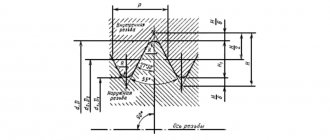
For internal thread
Dimensions, mm
An angle of 60° can be used.
Continuation of the table. 19
| 0,35 | 0,8 | 0,5 | 2,0 | 1,8 | — | — | — | — | — | — | — | — | — | — | 0,3 |
| 0,4 | 0,9 | 0,6 | |||||||||||||
| 0,45 | 1,1 | 0,7 | |||||||||||||
| 0,5 | 1,2 | 0,8 | 3,5 | 3,0 | 2,0* | 0,5 | 0,3 | 1,0 * | 0,3 | 0,2 | d+0.3 | 0,5 | |||
| 0,6 | 1,5 | 1,0 | — | — | — | — | — | — | — | ||||||
| 0,7 | 1,8 | 1,2 | |||||||||||||
| 0,75 | 1,9 | 1,3 | 4,0 | 3,2 | 3,0* | 1,0 | 0,5 | 1,6* | 0,5 | 0,3 | d+0.4 | 1,0 | |||
| 0,8 | 2,1 | 1,4 | — | — | — | — | — | — | — | ||||||
| 1 | 2,7 | 1,8 | 5,0 | 3,8 | 4,0 | 1,0 | 0,5 | 2,0 | 0,5 | 0,3 | 3,6 | 2,0 | d+0.5 | 2,0 | |
| 1,25 | 3,3 | 2,2 | 5,0 | 1,6 | 3,0 | 1,0 | 0,5 | 4,5 | 2,5 | 2,5 | 1,6 | ||||
| 1,5 | 4,0 | 2,7 | 6,0 | 4,5 | 6,0 | 1,0 | 5,4 | 3,0 | d+0.1 |
Continuation of the table. 19
| 1,75 | 4,7 | 3,2 | 7,0 | 5,2 | 7,0 | 1,6 | 1,0 | 4,0 | 1,0 | 0,5 | 6,2 | 3,5 | d+0.7 | 3,0 | 1,6 |
| 2 | 5,5 | 3,7 | 8,0 | 6,0 | 8,0 | 2,0 | 6,5 | d+1.0 | 2,0 | ||||||
| 2,5 | 7,0 | 4,7 | 10,0 | 7,5 | 10 | 3,0 | 5,0 | 1,6 | 1,0 | 8,9 | 5,0 | 4,0 | 2,5 | ||
| 3 | — | 5,7 | — | 9,0 | 6,0 | 11,4 | 6,5 | d+1.2 | |||||||
| 3,5 | 6,6 | 10,5 | 7,0 | 13,1 | 7,5 | 5,5 | 3,0 | ||||||||
| 4 | 7,6 | 12,5 | 12 | 8,0 | 2,0 | 14,3 | 8,0 | d+1.5 | |||||||
| 4,5 | 8,5 9,5 | 14,0 | 14 | 10 | 3,0 | 16,6 | 9,5 | 7,0 | 4,0 | ||||||
| 5 | 16,0 | 16 | 18,4 | 10,5 | d+1.8 | ||||||||||
| 5,5 | — | — | 12 | 18,7 | 8,0 | ||||||||||
| 6 | 18,9 | d+2.0 | 8,5 |
The width of the grooves is given for diameters of 6 mm or more.
GOST 10549-80 also provides dimensions for external and internal thread pitch of 0.2; 0.25 and 0.3mm.
Dimensions of runs, undercuts, grooves and chamfers for tapered pipe threads (GOST 10549-80)
Dimensions, mm
| Thread size designation | Number of steps per length 25.4mm | External thread | Internal thread | Chamfer z | ||||||||||
| Run-off x at an angle of the tool intake part of 20°, no more | Not enough, no more | Groove | Sbegh, no more | Not enough, no more | Groove | |||||||||
| f | R | R1 | df | f | R | R1 | df | |||||||
| 1/16 1/8 | 28 | 2,0 | 3,5 | 2 | 0,5 | 0,3 | 6,0 8,0 | 3,0 | 5,5 | 3 | 1,0 | 0,5 | 8,0 10,0 | 1,0 |
| 1/4 3/8 | 19 | 3,0 | 5,0 | 3 | 1,0 | 0,5 | 11,0 14,0 | 4,0 | 8,0 | 5 | 1,6 | 13,5 17,0 | 1,6 | |
Continuation of the table. 21
| 1/2 | 14 | 3,5 | 6,5 | 4 | 1,0 | 18,0 | 5,5 | 11,0 | 7 | 1,6 | 0,5 | 21,5 | 1,6 | |
| 3/4 | 23,5 | 27,0 | ||||||||||||
| 1 | 11 | 4,5 | 8,0 | 5 | 1,6 | 0,5 | 29,5 | 7,0 | 14,0 | 8 | 2,0 | 1,0 | 34,0 | 2,0 |
| 11/4 | 38,0 | 42,5 | ||||||||||||
| 1 1/2 | 44,0 | 48,5 | ||||||||||||
| 2 | 56,0 | 60,0 | ||||||||||||
| 2 1/2 | 71,0 | 76,0 | ||||||||||||
| 3 | 84,0 | 88,5 | ||||||||||||
| 3 1/2 | 98,0 | 101,0 | ||||||||||||
| 4 | 109,0 | 114,0 | ||||||||||||
| 5 | 134,5 | 139,5 | ||||||||||||
| 6 | 160,0 | 165,0 |
The width of narrow grooves for internal threads can be reduced to 1.5 steps. Dimensions are given for conical pipe threads in accordance with GOST 6211-81.
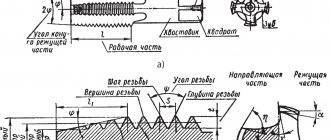
Thread exit Runaways, undercuts, grooves and chamfers
When making external cylindrical pipe threads, as well as point-blank threads with normal undercuts and groove widths, it is recommended to use a thread-forming tool with a chamfer angle of 20°; and with a reduced undercut and a narrow groove - with a intake angle of 30°.
For internal thread
Dimensions, mm
| Thread size designation | Number of steps per length 25.4 mm | Escape x, no more | Not enough, no more | Groove | Chamfer | ||||||||
| normal | decreased | normal | decreased | normal | narrow | df | |||||||
| f | R | R1 | f | R | R1 | ||||||||
| 1/16 1/8 | 28 | 2,2 | 1,4 | 4 | 2,5 | 4 | 1,0 | 0,5 | 2,5 | 1,0 | 0,5 | 8,0 10,0 | 1,0 |
| 1/4 3/8 | 19 | 3,3 | 2,0 | 5 | 3,0 | 5 | 1,6 | 3,0 | 13,5 17,0 | ||||
| 1/2 5/8 3/4 7/8 | 14 | 4,8 | 3,0 | 8 | 5,0 | 8 | 2,0 | 1,0 | 5,0 | 1,6 | 21,5 23,5 27,0 31,0 | 1,6 | |
| 1 | 11 | 6,0 | 4,0 | 10 | 6,0 | 10 | 3,0 | 1,0 | 6,0 | 1,6 | 1,0 | 34,0 | 1,6 |
| 1 1/8 | 39,0 | ||||||||||||
| 1 1/4 | 43,0 | ||||||||||||
| 1 3/8 | 45,0 | ||||||||||||
| 1 1/2 | 48,5 | ||||||||||||
| 1 3/4 | 54,5 | ||||||||||||
| 2 | 60,5 | ||||||||||||
| 2 1/4 | 66,5 | ||||||||||||
| 2 1/2 | 76,0 | ||||||||||||
| 2 3/4 | 82,5 | ||||||||||||
| 3 | 89,0 | ||||||||||||
| 3 1/4 | 95,0 | ||||||||||||
| 3 1/2 | 101,0 | ||||||||||||
| 4 | 114,0 | ||||||||||||
| 4 1/2 | 126,5 | ||||||||||||
| 5 | 139,5 | ||||||||||||
| 5 1/2 | 152,0 | ||||||||||||
| 6 | 165,0 | ||||||||||||
When making internal cylindrical pipe threads against a stop and with a normal undercut and groove width, it is recommended to use a thread-forming tool with a length of the intake part of no more than three steps, and with a reduced undercut and a narrow groove - with a length of the intake part of no more than two steps. The width of narrow grooves can be reduced to 1.5 steps.
21. Dimensions of runs, undercuts, grooves and chamfers for tubular conical threads (GOST 10549-80)
Dimensions, mm
For external thread For internal thread
| Thread size designation | Number of steps per length 25.4 mm | External thread | Internal thread | Chamfer z | ||||||||||
| Run-off x at an angle of the tool intake part of 20°, no more | Undercut, no more | Groove | Escape x, no more | Undercut A , no more | Groove | |||||||||
| f | R | R1 | df | f | R | R1 | df | |||||||
| 1/16 1/8 | 28 | 2,0 | 3,5 | 2 | 0,5 | 0,3 | 6,08,0 | 3,0 | 5,5 | 3 | 1,0 | 0,5 | 8,0 10,0 | 1,0 |
| 1/4 3/8 | 19 | 3,0 | 5,0 | 3 | 1,0 | 0,5 | 11,0 14,0 | 4,0 | 8,0 | 5 | 1,6 | 13,5 17,0 | 1,6 | |
| 1/2 3/4 | 14 | 3,5 | 6,5 | 4 | 1,0 | 0,5 | 18,0 23,5 | 5,5 | 11,0 | 7 | 1,6 | 0,5 | 21,5 27,0 | 1,6 |
| 1 11/411/2 | 11 | 4,5 | 8,0 | 5 | 1,6 | 29,5 38,0 44,0 | 7,0 | 14,0 | 8 | 2,0 | 1,0 | 34,0 42,5 48,5 | 2,0 | |
| 2 21/23 31/2 | 56,0 71,0 84,0 98,0 | 60,0 76,0 88,5 101,0 | ||||||||||||
| 4 5 6 | 109,0 134,5 160,0 | 114,0 139,5 165,0 | ||||||||||||
The width of narrow grooves for internal threads can be reduced to 1.5 pitches. Dimensions are given for conical pipe threads in accordance with GOST 6211-81.
22. Dimensions of runs, undercuts, grooves and chamfers according to GOST 10549-80 for tapered inch threads with a profile angle of 60°
(see sketch to table 21)
Dimensions, mm
| Thread size designation | Number of steps per length 25.4 mm | External thread | Internal thread | Chamfer z | ||||||||||
| Run-off x at an angle of the tool intake part of 20°, no more | Undercut, no more | Groove | Escape x, no more | Undercut a, no more | Groove | |||||||||
| f | R | R1 | df | f | R | R1 | df | |||||||
| 1/16 1/8 | 27 | 2,5 | 3,5 | 2 | 0,5 | 0,3 | 6 8 | 3,0 | 6 | 3 | 1,0 | 0,5 | 8,5 10,5 | 1,0 |
| 1/4 3/8 | 18 | 3,5 | 5,5 | 3 | 1,0 | 0,5 | 11 14 | 4,0 | 9 | 4 | 14,0 17,5 | 1,6 | ||
| 1/2 3/4 | 14 | 4,5 | 6,0 | 4 | 18 23 | 5,5 | 11 | 6 | 1,6 | 1,0 | 22,0 27,0 | |||
| 1 11/411/22 | 111/2 | 5,5 | 7,0 | 5 | 1,6 | 29 38 44 56 | 6,5 | 14 | 7 | 34,0 42,5 48,5 60,5 | 20 | |||
Dimensions are given for conical inch threads with a profile angle of 60° in accordance with GOST 6111-52 as amended. 1992
23. Dimensions of grooves and chamfers of the day of external and internal trapezoidal single-start threads (GOST 10549-80)
Dimensions, mm
For external thread For internal thread
For a multi-start trapezoidal thread, the width of the groove is taken equal to the width of the groove of a single-start thread, the pitch of which is equal to the stroke of the multi-start thread. The dimensions of the remaining elements should be taken according to the table. 23.
| Thread pitch | Groove | Chamfer z | ||||
| f | R | R1 | external thread df | internal thread df | ||
| 2 3 | 3 5 | 1,0 1,6 | 0,5 | d — 3.0 d — 4.2 | d+1.0 | 1,6 2,0 |
| 4 | 6 | 1,6 | 1,0 | d - 5.2 | d+1,1 | 2,5 |
| 5 6 | 8 10 | 2,0 3,0 | d - 7.0 d - 8.0 | d+1.6 | 3,0 3,5 | |
| 8 10 | 12 16 | 3,0 | d - 10.2 d - 12.5 | d+1.8 | 4,5 5,5 | |
| 12 | 18 | d - 14.5 | d+2,1 | 6,5 | ||
| 16 20 | 25 | 5,0 | 2,0 | d - 19.5 d - 24.0 | d+2.8 d+3.0 | 9,0 11,0 |
| 24 32 | 30 40 | d - 28.0 d - 36.5 | d+ 3.5 | 13,0 17,0 | ||
| 40 48 | 50 60 | d - 44.5 d - 52.8 | d+ 4.0 | 21,0 25,0 | ||
General instructions
:
1. Normal undercuts and undercuts should be used in preference. Narrow grooves and reduced undercuts may be used in justified cases. 2. May be used instead of the grooves indicated in the table. 20 - 23 at f £ 2 mm, symmetrical grooves (without chamfer) with a radius of curvature on both sides equal to R. 3. Maximum deviations of the groove sizes df and f are assigned based on the design requirements for the parts being manufactured. It is allowed to use the dimensions of run-offs, undercuts and grooves according to table 24.