Despite the fact that cutting internal threads is not a complex technological operation, there are some features of preparation for this procedure. Thus, it is necessary to accurately determine the dimensions of the preparation hole for threading, and also select the right tool, for which special tables of drill diameters for threads are used. For each type of thread, it is necessary to use the appropriate tool and calculate the diameter of the preparation hole.
The thread diameter and through hole must comply with the standards, otherwise the grooves will come out too small and the threaded connection will be unreliable
Types and parameters of thread
The parameters by which threads are divided into different types are:
- units of diameter (metric, inch, etc.);
- number of thread starts (one-, two- or three-thread);
- the shape in which the profile elements are made (triangular, rectangular, round, trapezoidal);
- direction of rise of turns (right or left);
- location on the product (external or internal);
- surface shape (cylindrical or conical);
- purpose (fastening, fastening and sealing, chassis).
Metric thread parameters
Depending on the above parameters, the following types of thread are distinguished:
- cylindrical, which is designated by the letters MJ;
- metric and conical, designated M and MK respectively;
- pipe, designated by the letters G and R;
- with a round profile, named after Edison and marked with the letter E;
- trapezoidal, designated Tr;
- round, used for installation of sanitary fittings, – Kr;
- thrust and thrust reinforced, marked as S and S45, respectively;
- inch thread, which can also be cylindrical and conical - BSW, UTS, NPT;
- used to connect pipes installed in oil wells.
Thread types according to GOST
TECHNOLOGICAL ELEMENTS OF THREAD
The technological elements of threads include runs, undercuts, grooves and chamfers. The shape and dimensions of these elements, depending on the thread profile, are established by the relevant GOST standards.
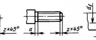
The thread run-out is the section of the thread in which the cutting tool, emerging from the metal (or other material) to the surface, cuts a thread with a gradual decrease in the profile height. The carving in the drawing, as a rule, is shown without a runoff, but if it needs to be shown, then the runway is shown with thin, solid straight lines, as shown in Fig. 406. The size of the thread length in the drawing is indicated before the run-out, but if necessary, indicate the length of the thread with the run-out (Fig. 406, b)
or indicate the length of the thread before the run-out and the amount of run-out (
x
) (Fig. 406,
a).
In the drilled blind hole, a conical recess is formed from the drill, which is always drawn in the drawing with an angle at the apex of the cone equal to 120° (Fig. 406, b).
The dimensions of this recess are not indicated in the drawing.
The hole drilling depth ( l
) is set without taking into account the cone.
The determining size for the rungs is the thread pitch P.
The undercut of the thread is the area that includes the rung and the remaining uncut part of the rod or hole (Fig. 407). An undercut occurs when cutting a thread point-blank, when there is a protruding surface on the rod and the bottom in the hole prevents further passage of the cutting tool (Fig. 407, a and b).
The dimensions of undercuts are established by GOST 10549-80.
The determining size is the thread pitch P.
It is allowed to depict an undercut with thin solid lines, as shown in Fig.
407, v.
Grooves are performed when cutting threads on machines using a cutter in order to avoid thread runaway and obtain its full profile, as well as to ensure free exit of the cutting tool. To do this, the diameter of the external groove is made smaller than the internal diameter of the thread, and the diameter of the internal groove is larger than the external diameter of the thread (Fig. 408).
In the drawings, grooves are depicted in a simplified manner and, if necessary, explained with a remote element on which the shape of the groove is shown and its dimensions are indicated (Fig. 408). Depending on the scale at which the drawing is made, it is possible to depict the shape of the groove and plot its dimensions on the image of the part itself, as shown in Fig. 409. The dimensions of the groove and its shape are established by GOST 10549-80, depending on the type of thread and its pitch.
Chamfers are made at the end of the rod and at the beginning of the hole. They simplify the thread cutting process and contribute to a more convenient and quick connection of two parts, like guide elements. The chamfer is a small truncated cone, the height of which is indicated by the letter z
, and the angle of inclination of the generatrices is 45° (Fig. 409 and 410). The dimensions of chamfers for metric threads are established by GOST 10549-80.
The technological elements of threads include runs, undercuts, grooves and chamfers. The shape and dimensions of these elements, depending on the thread profile, are established by the relevant GOST standards.
The thread run-out is the section of the thread in which the cutting tool, emerging from the metal (or other material) to the surface, cuts a thread with a gradual decrease in the profile height. The carving in the drawing, as a rule, is shown without a runoff, but if it needs to be shown, then the runway is shown with thin, solid straight lines, as shown in Fig. 406. The size of the thread length in the drawing is indicated before the run-out, but if necessary, indicate the length of the thread with the run-out (Fig. 406, b)
or indicate the length of the thread before the run-out and the amount of run-out (
x
) (Fig. 406,
a).
In the drilled blind hole, a conical recess is formed from the drill, which is always drawn in the drawing with an angle at the apex of the cone equal to 120° (Fig. 406, b).
The dimensions of this recess are not indicated in the drawing.
The hole drilling depth ( l
) is set without taking into account the cone.
The determining size for the rungs is the thread pitch P.
The undercut of the thread is the area that includes the rung and the remaining uncut part of the rod or hole (Fig. 407). An undercut occurs when cutting a thread point-blank, when there is a protruding surface on the rod and the bottom in the hole prevents further passage of the cutting tool (Fig. 407, a and b).
The dimensions of undercuts are established by GOST 10549-80.
The determining size is the thread pitch P.
It is allowed to depict an undercut with thin solid lines, as shown in Fig.
407, v.
Grooves are performed when cutting threads on machines using a cutter in order to avoid thread runaway and obtain its full profile, as well as to ensure free exit of the cutting tool. To do this, the diameter of the external groove is made smaller than the internal diameter of the thread, and the diameter of the internal groove is larger than the external diameter of the thread (Fig. 408).
In the drawings, grooves are depicted in a simplified manner and, if necessary, explained with a remote element on which the shape of the groove is shown and its dimensions are indicated (Fig. 408). Depending on the scale at which the drawing is made, it is possible to depict the shape of the groove and plot its dimensions on the image of the part itself, as shown in Fig. 409. The dimensions of the groove and its shape are established by GOST 10549-80, depending on the type of thread and its pitch.
Chamfers are made at the end of the rod and at the beginning of the hole. They simplify the thread cutting process and contribute to a more convenient and quick connection of two parts, like guide elements. The chamfer is a small truncated cone, the height of which is indicated by the letter z
, and the angle of inclination of the generatrices is 45° (Fig. 409 and 410). The dimensions of chamfers for metric threads are established by GOST 10549-80.
Application of the tap
Before you start threading, you need to determine the diameter of the preparation hole and drill it. To facilitate this task, a corresponding GOST was developed, which contains tables that allow you to accurately determine the diameter of the threaded hole. This information makes it easy to select the drill size.
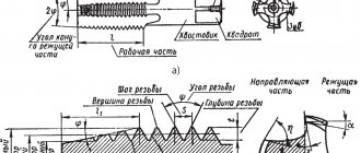
To cut metric threads on the inner walls of a hole made with a drill, a tap is used - a screw-shaped tool with cutting grooves, made in the form of a rod, which can have a cylindrical or conical shape. On its side surface there are special grooves located along its axis and dividing the working part into separate segments, which are called combs. The sharp edges of the combs are precisely the working surfaces of the tap.
Tap: design and parameters
In order for the turns of the internal thread to be clean and neat, and for its geometric parameters to correspond to the required values, it must be cut gradually, by gradually removing thin layers of metal from the surface being treated. That is why for this purpose they use either taps, the working part of which is divided along the length into sections with different geometric parameters, or sets of such tools. Single taps, the working part of which has the same geometric parameters along its entire length, are needed in cases where it is necessary to restore the parameters of an existing thread.
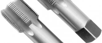
The minimum set with which you can sufficiently perform machining of threaded holes is a set consisting of two taps - rough and finishing. The first one cuts a thin layer of metal from the walls of the hole for cutting metric threads and forms a shallow groove on them, the second one not only deepens the formed groove, but also cleans it.
Types of thread taps and their differences
Minimum set of taps
Combination two-pass taps or sets consisting of two tools are used for tapping small diameter holes (up to 3 mm). To machine holes for larger metric threads, you must use a combination three-pass tool or a set of three taps.
To manipulate the tap, a special device is used - a wrench. The main parameter of such devices, which can have different designs, is the size of the mounting hole, which must exactly match the size of the tool shank.
Some types of tap drivers
When using a set of three taps that differ both in their design and geometric parameters, the sequence of their use must be strictly observed. They can be distinguished from each other both by special marks applied to the shanks and by design features.
- The tap, with which the hole for cutting metric threads is processed first, has the smallest diameter among all the tools in the set and cutting teeth, the upper part of which is heavily cut off.
- The second tap has a shorter fence and longer combs. Its working diameter is intermediate between the diameters of the other tools in the set.
- The third tap, with which the hole for cutting metric threads is processed last, is characterized by full ridges of cutting teeth and a diameter that must exactly match the size of the thread being formed.
Set of three taps
Taps are used primarily for cutting metric threads. Much less often than metric ones, taps designed for processing the internal walls of pipes are used. In accordance with their purpose, they are called pipe, and they can be distinguished by the letter G present in their markings.
American thread with extra fine pitch – UNEF
| Thread size | Threads per inch | D - outer diameter | Dp - average diameter | Di - internal diameter | Thread pitch | |
| inches | mm | millimeters | ||||
| #12 | 5,49 | 32 | 5,49 | 4,97 | 4,63 | 0,79 |
| 1/4 | 6,35 | 32 | 6,35 | 5,83 | 5,49 | 0,79 |
| 5/16 | 7,94 | 32 | 7,94 | 7,42 | 7,08 | 0,79 |
| 3/8 | 9,53 | 32 | 9,53 | 9,01 | 8,67 | 0,79 |
| 7/16 | 11,1 | 28 | 11,11 | 10,52 | 10,13 | 0,91 |
| 1/2 | 12,7 | 28 | 12,70 | 12,11 | 11,72 | 0,91 |
| 9/16 | 14,3 | 24 | 14,29 | 13,60 | 13,14 | 1,06 |
| 5/8 | 15,9 | 24 | 15,88 | 15,19 | 14,73 | 1,06 |
| 11/16 | 17,5 | 24 | 17,46 | 16,77 | 16,32 | 1,06 |
| 3/4 | 19,1 | 20 | 19,05 | 18,22 | 17,68 | 1,27 |
| 13/16 | 20,6 | 20 | 20,64 | 19,81 | 19,26 | 1,27 |
| 7/8 | 22,2 | 20 | 22,23 | 21,40 | 20,85 | 1,27 |
| 15/16 | 23,8 | 20 | 23,81 | 22,99 | 22,44 | 1,27 |
| 7/16 | 11,1 | 20 | 11,11 | 10,29 | 9,74 | 1,27 |
| 1 | 25,4 | 20 | 25,40 | 24,57 | 24,03 | 1,27 |
| 1 1/16 | 26,9 | 18 | 26,99 | 26,07 | 25,46 | 1,41 |
| 1 1/8 | 28,6 | 18 | 28,58 | 27,66 | 27,05 | 1,41 |
| 1 3/16 | 30,2 | 18 | 30,16 | 29,25 | 28,64 | 1,41 |
| 1 1/4 | 31,8 | 18 | 31,75 | 30,83 | 30,22 | 1,41 |
| 1 5/16 | 33,3 | 18 | 33,40 | 32,42 | 31,81 | 1,41 |
| 1 3/8 | 34,9 | 18 | 34,93 | 34,01 | 33,40 | 1,41 |
| 1 7/16 | 36,5 | 18 | 36,51 | 35,60 | 34,99 | 1,41 |
| 1 1/2 | 38,1 | 18 | 38,10 | 37,18 | 36,57 | 1,41 |
| 1 9/16 | 39,7 | 18 | 39,69 | 38,77 | 38,16 | 1,41 |
| 1 5/8 | 41,3 | 18 | 41,27 | 40,36 | 39,75 | 1,41 |
| 1 11/16 | 42,9 | 18 | 42,86 | 41,95 | 41,34 | 1,41 |
Internal thread cutting technology
As mentioned above, before starting work, you need to drill a hole, the diameter of which must exactly fit a thread of a certain size. It should be borne in mind: if the diameters of the holes intended for cutting metric threads are chosen incorrectly, this can lead not only to poor quality execution, but also to breakage of the tap.
Considering the fact that the tap, when forming threaded grooves, not only cuts the metal, but also pushes it, the diameter of the drill for making threads should be slightly smaller than its nominal diameter. For example, a drill for making M3 threads should have a diameter of 2.5 mm, for M4 - 3.3 mm, for M5 you should choose a drill with a diameter of 4.2 mm, for M6 threads - 5 mm, M8 - 6.7 mm, M10 - 8.5 mm, and for M12 - 10.2.
Table 1. Main diameters of holes for metric threads
Table 2. Diameters of holes for inch threads
All diameters of drills for GOST threads are given in special tables. Such tables indicate the diameters of drills for making threads with both standard and reduced pitches, but it should be borne in mind that holes of different diameters are drilled for these purposes. In addition, if threads are cut in products made of brittle metals (such as cast iron), the diameter of the thread drill obtained from the table must be reduced by one tenth of a millimeter.
You can familiarize yourself with the provisions of GOST regulating the cutting of metric threads by downloading the document in pdf format from the link below.
The diameters of drills for metric threads can be calculated independently. From the diameter of the thread that needs to be cut, it is necessary to subtract the value of its pitch. The thread pitch itself, the size of which is used when performing such calculations, can be found out from special correspondence tables. In order to determine what diameter the hole needs to be made using a drill if a three-start tap is used for threading, you must use the following formula:
Differences from metric threads
In terms of their external features and characteristics, metric and inch threads do not have many differences, the most significant of which include:
- profile shape of the threaded ridge;
- procedure for calculating diameter and pitch.
Differences in thread profile
When comparing the shapes of threaded ridges, you can see that in inch threads such elements are sharper than in metric threads. If we talk about exact dimensions, the angle at the top of the ridge of an inch thread is 55°.
The parameters of metric and inch threads are characterized by different units of measurement. So, the diameter and pitch of the former are measured in millimeters, and the latter, respectively, in inches. It should, however, be borne in mind that in relation to an inch thread, it is not the generally accepted one (2.54 cm), but a special pipe inch equal to 3.324 cm that is used. Thus, if, for example, its diameter is ¾ inch, then in terms of millimeters it will correspond to the value 25.
To find out the basic parameters of an inch thread of any standard size, which is fixed by GOST, just look at the special table. The tables containing inch thread sizes contain both whole and fractional values. It should be borne in mind that the pitch in such tables is given in the number of cut grooves (threads) contained in one inch of product length.
Drawing. Main profile parameters according to GOST
Table 1. Main thread profile dimensions
Table 2. Basic parameters of pipe threads
To check whether the pitch of the thread already made corresponds to the dimensions specified by GOST, this parameter must be measured. For such measurements, carried out for both metric and inch threads using the same algorithm, standard tools are used - a comb, a gauge, a mechanical gauge, etc.
The easiest way to measure the pitch of an inch pipe thread is using the following method:
- As a simple template, a coupling or fitting is used, the internal thread parameters of which exactly correspond to the requirements given by GOST.
- The bolt, the external thread parameters of which need to be measured, is screwed into the coupling or fitting.
- If the bolt has formed a tight threaded connection with the coupling or fitting, then the diameter and pitch of the thread that is applied to its surface exactly correspond to the parameters of the template used.
Inch thread pitch is the number of threads per inch
If the bolt does not screw into the template or screws in but creates a loose connection with it, then such measurements should be carried out using another coupling or another fitting. The internal pipe thread is measured using a similar technique, only in such cases a product with an external thread is used as a template.
The required dimensions can be determined using a thread gauge, which is a plate with notches, the shape and other characteristics of which exactly correspond to the parameters of the thread with a certain pitch. Such a plate, acting as a template, is simply applied to the thread being checked with its serrated part. The fact that the thread on the element being tested corresponds to the required parameters will be indicated by a tight fit of the jagged part of the plate to its profile.
Using a thread gauge for inch threads
To measure the outside diameter of an inch or metric thread, you can use a regular caliper or micrometer.
Dimensions and maximum deviations of the diameters of holes of threads with a large pitch
2,052,07+0,07+0,09—30,52,502,52+0,08+0,19+0,143,50,62,902,93+0,08+0,11+0,1540,73,303,33+0,08+0,12+0,164,50,753,703,73+0,09+0,17+0,1850,84,204,23+0,11+0,19+0,22614,955,0+0,17+0,20+0,2681,256,706,75+0,17+0,20+0,26101,58,438,50+0,19+0,22+0,30121,7510,2010,25+0,21+0,27+0,3614211,9011,95+0,24+0,30+0,401613,9013,95182,515,3515,40+0,30+0,40+0,532017,3517,402219,3519,4024320,8520,90+0,30+0,40+0,532723,8523,90303,526,3026,35+0,36+0,48+0,62333,529,3029,3536431,8031,8539434,8034,85+0,36+0,48+0,62424,537,2537,30+0,41+0,55+0,73454,540,2540,30+0,41+0,55+0,7348542,7042,80+0,45+0,60+0,805246,7046,80565,550,2050,306054,2054,3064657,7057,806861,7061,80GOST provides holes for threads with large pitch d = 1.0 ÷ 2.2 mm
American thread with coarse pitch - UNC
| Thread size | Threads per inch | D - outer diameter | Dp - average diameter | Di - internal diameter | Thread pitch, mm | |
| inches | mm | millimeters | ||||
| #1 | 1,85 | 64 | 1,85 | 1,6 | 1,42 | 0,40 |
| #2 | 2,18 | 56 | 2,18 | 1,89 | 1,69 | 0,45 |
| #3 | 2,51 | 48 | 2,51 | 2,17 | 1,94 | 0,53 |
| #4 | 2,84 | 40 | 2,84 | 2,43 | 2,16 | 0,64 |
| #5 | 3,17 | 40 | 3,18 | 2,76 | 2,49 | 0,64 |
| #6 | 3,50 | 32 | 3,51 | 2,99 | 2,65 | 0,79 |
| #8 | 4,16 | 32 | 4,17 | 3,65 | 3,31 | 0,79 |
| #10 | 4,83 | 24 | 4,83 | 4,14 | 3,68 | 1,06 |
| #12 | 5,49 | 24 | 5,49 | 4,8 | 4,34 | 1,06 |
| 1/4 | 6,35 | 20 | 6,35 | 5,52 | 4,98 | 1,27 |
| 5/16 | 7,94 | 18 | 7,94 | 7,02 | 6,41 | 1,41 |
| 3/8 | 9,53 | 16 | 9,53 | 8,49 | 7,81 | 1,59 |
| 7/16 | 11,1 | 14 | 11,11 | 9,93 | 9,15 | 1,81 |
| 1/2 | 12,7 | 13 | 12,70 | 11,43 | 10,58 | 1,95 |
| 9/16 | 14,3 | 12 | 14,29 | 12,91 | 12,00 | 2,12 |
| 5/8 | 15,9 | 11 | 15,88 | 14,38 | 13,38 | 2,31 |
| 3/4 | 19,1 | 10 | 19,05 | 17,40 | 16,30 | 2,54 |
| 7/8 | 22,2 | 9 | 22,23 | 20,39 | 19,17 | 2,82 |
| 1 | 25,4 | 8 | 25,40 | 23,34 | 21,96 | 3,18 |
| 1 1/8 | 28,6 | 7 | 28,58 | 26,22 | 24,65 | 3,63 |
| 1 1/4 | 31,8 | 7 | 31,75 | 29,39 | 27,82 | 3,63 |
| 1 3/8 | 34,9 | 6 | 36,93 | 32,17 | 30,34 | 4,23 |
| 1 1/2 | 38,1 | 5 | 38,10 | 35,35 | 33,52 | 4,23 |
| 1 3/4 | 44,4 | 5 | 44,45 | 41,15 | 38,95 | 5,08 |
| 2 | 50,8 | 4 1/2 | 50,80 | 47,13 | 44,69 | 5,64 |
| 2 1/4 | 57,1 | 4 1/2 | 57,15 | 53,48 | 51,04 | 5,64 |
| 2 1/2 | 63,5 | 4 | 63,50 | 59,38 | 56,63 | 6,35 |
| 2 3/4 | 69,9 | 4 | 69,85 | 65,73 | 62,98 | 6,35 |
| 3 | 76,2 | 4 | 76,20 | 72,08 | 69,33 | 6,35 |
| 3 1/4 | 82,5 | 4 | 82,55 | 78,43 | 75,68 | 6,35 |
| 3 1/2 | 88,9 | 4 | 88,9 | 84,78 | 75,68 | 6,35 |
| 3 3/4 | 95,2 | 4 | 95,25 | 91,13 | 88,38 | 6,35 |
| 4 | 101,6 | 4 | 101,60 | 97,48 | 94,73 | 6,35 |
Dimensions and maximum deviations of the diameters of fine-pitch thread holes
| Nominal thread diameter d | Thread pitch P | Thread hole diameter with tolerance range | ||||
| 4H5H; 5H; 5H6H; 6H; 7H | 6G; 7G | 4H5H; 5H | 5H6H; 6H; 6G | 7H; 7G | ||
| Denomination | Deviations | |||||
| 2,5 | 0,35 | 2,15 | 2,17 | +0,05 | +0,07 | — |
| 3 | 2,65 | 2,67 | ||||
| 3,5 | 3,15 | 3,17 | ||||
| 4 | 0,5 | 3,50 | 3,52 | +0,08 | +0,10 | +0,14 |
| 4,5 | 4,00 | 4,02 | ||||
| 5 | 4,50 | 4,52 | ||||
| 5,5 | 5,00 | 5,02 | ||||
| 6 | 0,5 | 5,50 | 5,52 | +0,08 | +0,10 | +0,14 |
| 0,75 | 5,20 | 5,23 | +0,11 | +0,17 | +0,22 | |
| 8 | 0,5 | 7,50 | 7,52 | +0,08 | +0,10 | +0,14 |
| 0,75 | 7,20 | 7,23 | +0,11 | +0,17 | +0,22 | |
| 1 | 6,95 | 7,00 | +0,17 | +0,20 | +0,26 | |
| 10 | 0,5 | 9,50 | 9,53 | +0,08 | +0,10 | +0,14 |
| 0,75 | 9,20 | 9,23 | +0,11 | +0,17 | +0,22 | |
| 1 | 8,95 | 9,00 | +0,17 | +0,20 | +0,26 | |
| 1,25 | 8,70 | 8,75 | +0,17 | +0,20 | +0,26 | |
| 12 | 0,5 | 11,50 | 11,52 | +0,08 | +0,10 | +0,14 |
| 0,75 | 11,20 | 11,23 | +0,11 | +0,17 | +0,22 | |
| 1 | 10,99 | 11,00 | +0,17 | +0,17 | +0,26 | |
| 1,25 | 10,70 | 10,75 | +0,17 | +0,20 | +0,26 | |
| 1,5 | 10,43 | 10,50 | +0,19 | +0,22 | +0,30 | |
| 14 | 0,5 | 13,50 | 13,52 | +0,08 | +0,10 | +0,14 |
| 0,75 | 13,20 | 13,23 | +0,11 | +0,17 | +0,22 | |
| 1 | 12,95 | 13,00 | +0,17 | +0,20 | +0,26 | |
| 1,25 | 12,70 | 12,75 | +0,17 | +0,20 | +0,26 | |
| 1,5 | 12,43 | 12,50 | +0,19 | +0,22 | +0,30 | |
| 16 | 0,5 | 15,50 | 15,52 | +0,08 | +0,10 | +0,14 |
| 0,75 | 15,20 | 15,23 | +0,11 | +0,17 | +0,22 | |
| 1 | 14,95 | 15,00 | +0,17 | +0,20 | +0,26 | |
| 1,5 | 14,43 | 14,50 | +0,19 | +0,22 | +0,30 | |
| 18 | 0,5 | 17,50 | 17,52 | +0,08 | +0,10 | +0,14 |
| 0,75 | 17,20 | 17,23 | +0,11 | +0,17 | +0,22 | |
| 1 | 16,95 | 17,00 | +0,17 | +0,20 | +0,26 | |
| 1,25 | 16,43 | 16,50 | +0,19 | +0,22 | +0,30 | |
| 1,5 | 15,90 | 15,95 | +0,24 | +0,30 | +0,40 | |
| 20 | 0,5 | 19,50 | 19,52 | +0,08 | +0,10 | +0,14 |
| 0,75 | 19,20 | 19,23 | +0,11 | +0,17 | +0,22 | |
| 1 | 18,95 | 19,00 | +0,17 | +0,20 | +0,26 | |
| 1,5 | 18,43 | 18,50 | +0,19 | +0,22 | +0,30 | |
| 2 | 17,90 | 17,95 | +0,24 | +0,30 | +0,40 | |
| 22 | 0,5 | 21,50 | 21,52 | +0,08 | +0,10 | +0,14 |
| 0,75 | 21,20 | 21,23 | +0,11 | +0,17 | +0,22 | |
| 1 | 20,95 | 21,00 | +0,17 | +0,20 | +0,26 | |
| 1,5 | 20,43 | 20,50 | +0,19 | +0,22 | +0,30 | |
| 2 | 19,90 | 19,95 | +0,24 | +0,30 | +0,40 | |
| 24 | 0,75 | 23,20 | 23,23 | +0,11 | +0,17 | +0,22 |
| 1 | 22,95 | 23,00 | +0,17 | +0,20 | +0,26 | |
| 1,5 | 22,43 | 22,50 | +0,19 | +0,22 | +0,30 | |
| 2 | 21,90 | 21,95 | +0,24 | +0,30 | +0,40 | |
| 27 | 0,75 | 26,20 | 26,23 | +0,11 | +0,17 | +0,22 |
| 1 | 25,95 | 26,00 | +0,17 | +0,20 | +0,26 | |
| 1,5 | 25,43 | 25,50 | +0,19 | +0,22 | +0,30 | |
| 2 | 24,90 | 24,95 | +0,24 | +0,30 | +0,40 | |
| 30 | 0,75 | 29,20 | 29,23 | +0,11 | +0,17 | +0,22 |
| 1 | 28,95 | 29,00 | +0,17 | +0,20 | +0,26 | |
| 1,5 | 28,43 | 28,50 | +0,19 | +0,22 | +0,30 | |
| 2 | 27,90 | 27,95 | +0,24 | +0,30 | +0,40 | |
| 3 | 26,85 | 26,90 | +0,30 | +0,40 | +0,53 | |
| 33 | 0,75 | 32,20 | 32,23 | +0,11 | +0,17 | +0,22 |
| 1 | 31,95 | 32,00 | +0,17 | +0,20 | +0,26 | |
| 1,5 | 31,43 | 31,50 | +0,19 | +0,22 | +0,30 | |
| 2 | 30,90 | 30,95 | +0,24 | +0,30 | +0,40 | |
| 3 | 29,85 | 29,90 | +0,30 | +0,40 | +0,53 | |
| 36 | 1 | 34,95 | 35,00 | +0,17 | +0,20 | +0,26 |
| 1,5 | 34,43 | 34,50 | +0,19 | +0,22 | +0,30 | |
| 2 | 33,90 | 33,95 | +0,24 | +0,30 | +0,40 | |
| 3 | 32,85 | 32,90 | +0,30 | +0,40 | +0,53 | |
| 39 | 1 | 37,95 | 38,00 | +0,17 | +0,20 | +0,26 |
| 1,5 | 37,43 | 37,50 | +0,19 | +0,22 | +0,30 | |
| 2 | 36,90 | 36,95 | +0,24 | +0,30 | +0,40 | |
| 3 | 35,85 | 35,90 | +0,30 | +0,40 | +0,53 | |
| 42 | 1 | 40,95 | 41,00 | +0,17 | +0,20 | +0,26 |
| 1,5 | 40,43 | 40,50 | +0,19 | +0,22 | +0,30 | |
| 2 | 39,90 | 39,95 | +0,24 | +0,30 | +0,40 | |
| 3 | 38,85 | 38,90 | +0,30 | +0,40 | +0,53 | |
| 4 | 37,80 | 37,85 | +0,36 | +0,48 | +0,62 | |
| 45 | 1 | 43,95 | 44,00 | +0,17 | +0,20 | +0,26 |
| 1,5 | 43,43 | 43,50 | +0,19 | +0,22 | +0,30 | |
| 2 | 42,90 | 42,95 | +0,24 | +0,30 | +0,40 | |
| 3 | 41,85 | 41,90 | +0,30 | +0,40 | +0,53 | |
| 4 | 40,80 | 40,85 | +0,36 | +0,48 | +0,62 | |
GOST provides holes for threads with d = 1.0 ÷ 200 mm and for the 3rd row.
GOST provides a method for determining the diameters of holes for cutting metric threads for materials of high viscosity.
Source: razvitie-pu.ru
American fine pitch thread - UNF
| Thread size | Threads per inch | D - outer diameter | Dp - average diameter | Di - internal diameter | Thread pitch | |
| inches | mm | millimeters | ||||
| #0 | 1,52 | 80 | 1,52 | 1,32 | 1,18 | 0,32 |
| #1 | 1,85 | 72 | 1,85 | 1,63 | 1,47 | 0,35 |
| #2 | 2,18 | 64 | 2,18 | 1,93 | 1,76 | 0,40 |
| #3 | 2,51 | 56 | 2,51 | 2,22 | 2,02 | 0,45 |
| #4 | 2,84 | 48 | 2,84 | 2,50 | 2,27 | 0,53 |
| #5 | 3,17 | 44 | 3,18 | 2,80 | 2,55 | 0,58 |
| #6 | 3,51 | 40 | 3,51 | 3,09 | 2,82 | 0,63 |
| #8 | 4,17 | 36 | 4,17 | 3,71 | 3,4 | 0,71 |
| #10 | 4,83 | 32 | 4,83 | 4,31 | 3,88 | 0,79 |
| #12 | 5,49 | 28 | 5,49 | 4,90 | 4,40 | 0,91 |
| 1/4 | 6,35 | 28 | 6,35 | 5,76 | 5,37 | 0,91 |
| 5/16 | 7,94 | 24 | 7,94 | 7,25 | 6,79 | 1,06 |
| 3/8 | 9,53 | 24 | 9,53 | 8,84 | 8,38 | 1,06 |
| 7/16 | 11,1 | 20 | 11,11 | 10,29 | 9,74 | 1,27 |
| 1/2 | 12,7 | 20 | 12,70 | 11,87 | 11,33 | 1,27 |
| 9/16 | 14,3 | 18 | 14,29 | 13,37 | 12,76 | 1,41 |
| 5/8 | 15,9 | 18 | 15,88 | 14,96 | 14,35 | 1,41 |
| 3/4 | 19,1 | 16 | 19,05 | 18,02 | 17,33 | 1,59 |
| 7/8 | 22,2 | 14 | 22,23 | 21,05 | 20,26 | 1,81 |
| 1 | 25,4 | 12 | 25,40 | 24,03 | 23,11 | 2,12 |
| 1 1/8 | 28,6 | 12 | 28,58 | 27,20 | 26,28 | 2,12 |
| 1 1/4 | 31,8 | 12 | 31,75 | 30,38 | 29,46 | 2,12 |
| 1 3/8 | 34,9 | 12 | 34,93 | 33,55 | 32,63 | 2,12 |
| 1 1/2 | 38,1 | 12 | 38,10 | 36,73 | 35,81 | 2,12 |