A thread drill is a metal-cutting tool that is used before using a tap or similar device. It is necessary that all parameters comply with current requirements and standards. Otherwise, the fastening will be unreliable.
To select the optimal drill diameter for threads, special tables have been developed. The value depends on the type of cut. Requirements for drill size and metric hole parameters are regulated by the interstate standard GOST 19257-73. As an auxiliary tool, it is necessary to use a caliper or other device to calculate the size and pitch of the thread.
Hole parameters
Threads are distinguished according to the following characteristics:
- Unit of measurement. Throughout the country, the metric system is predominantly used. Inch values were used in the pipe industry.
Abroad, the inch system is considered the main one. Owners of cars that were assembled for the American market know that there is not a single element with metric cutting.
- Thread pitch and number of thread starts. Non-standard parameters are used in the automotive and machine tool industries.
- Profile form. The figures differ in the type of cutting. There are elements of triangular, rectangular, trapezoidal and round shapes.
- Direction of turns. There are right- and left-handed cuts.
- View. External or internal.
- Surface type. It can be cylindrical or conical.
The main condition for a high-quality connection is the correspondence of the indicators of the external and internal threads. If one of the parameters does not match, the fastening will be unreliable.
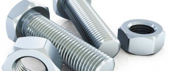
The most common threaded connection methods are bolt and stud fasteners. In the latter case, in addition to the main device, nuts and washers are used as auxiliary elements.
Pre-drilling holes is an essential procedure prior to cutting. In this case, the diameter of the gimlet should be slightly smaller than the size of the bolt or stud.
Drilling depth is one of the most important indicators. When calculating, the following factors must be taken into account:
- screw-in depth of the threaded element;
- the size of the external thread;
- presence and chamfer parameters.
To calculate the screw depth, the type of material being processed must be taken into account. For steel, titanium, bronze and brass no corrections are needed, but for gray and ductile cast iron a multiplying factor of 1.25 is used. For light alloys this figure is even higher - it is doubled.
Device Features
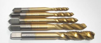
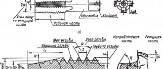
At first, a three- or four-sided rod was used, on which the teeth were cut. The end was sharpened into a shallow cone. When screwing such an artifact into the hole of a nut or body, toothed bridges cut an internal thread. It is clear that such a tool was far from perfect, since the cutting teeth did not have a back angle, and the front angle was negative. However, its design was gradually improved until it became more rational. Today, any tap for threading has similar design elements:
- Grooves for the release of chips and the supply of cooling and lubricating fluid (coolant). Their number is usually from 2 to 6 .
- The profile of the depressions can be different: single-radius, straight front and rear surfaces, straight front and radius rear.
- Groove direction: straight, spiral right and left . The former are used in conventional universal taps. Flutes with a left-handed helical line are used to cut threads for passage. In this case, the chips go in front of the tap so as not to spoil the cutting. Right-hand recesses are used for blind holes so that the chips are brought back, otherwise they, being compressed, will break the tool.
- The intake part is made conical in order to facilitate cutting of the cutting teeth into the material of the part . The tilt angle is from 3 to 20 degrees, depending on the purpose of the tap (roughing, intermediate, finishing).
- The calibrating part is cylindrical, has a reverse lowering of up to 0.1 mm, which serves to reduce the friction force . For the same purpose, the calibrating teeth are backed at a distance of 1/3 of the width of the feather from the top of the tooth. The reduction is about one tenth of a millimeter for threads with a diameter of 12 to 30 mm.
Drill and hole size chart for metric and inch threads
Let's consider the calculation results from GOST 19257-73:
- For M3 threads, a tap is required, for which the standard pitch is 0.5, drills are 2.5 mm.
- For M4 threads, a tap is required, for which the standard pitch is 0.7, drill bits are 3.3 mm.
- For M5 threads, a tap is required, for which the standard pitch is 0.8, drill bits are 4.2 mm.
- For M6 threads, a tap is required, for which the standard pitch is 1.0, drill bits are 5.0 mm.
- For M8 threads, a tap is required, for which the standard pitch is 1.25, drill bits are 6.75 mm.
- For M10 threads, a tap is required, for which the standard pitch is 1.5, drills are 8.5 mm.
- For M12 threads, a tap is required, for which the standard pitch is 1.75, drill bits are 10.25 mm.
- For M16 threads, a tap is required, for which the standard pitch is 2.0, drills are 13.5 mm.
Despite the fact that the metric system is the most popular, we recommend that you familiarize yourself with the table of threaded drill diameters:
Buy a screw thread set from AliExpress from 105 rubles →
Thread cutting tools
To form an internal thread in a part, a specialized tool is used - taps. They are cylindrical rods with a cut thread profile in a mirror image. But before using the tap, it is necessary to obtain a hole with the required diameter in the workpiece. We will explain below what the diameters of drills for threads should be, and in this section we will describe the thread-cutting tool.
In addition to the screw profile, the cylindrical surface of the tap has longitudinal grooves, which extend beyond the working part of the tool in size. These grooves are designed to remove metal shavings from the working area. In addition, these axial grooves divide the tap rod into several elements - combs. Their sharp edges are the main working elements of the tap. The tail part and square of the tool are designed for fixation in the spindle and chuck of the machine or in the driver. The working area of the tap is divided into cutting and calibrating parts. The cutting or tapping part cuts a groove in the hole, and the calibration part brings the dimensions of the thread profile into exact compliance with the required ones.
If one universal tap is used for cutting, then along its length it will have several areas with different characteristics of the working profile. This allows you to simultaneously cut out a layer of metal, remove burrs and irregularities, and also bring the dimensions to the required value. Taps, whose working profile has constant dimensions, are used to update the damaged profile of an existing internal thread. But more often in practice, several taps are used, which are used in turn.
The roughing tap cuts a groove of insignificant thickness on the inner cylindrical surface, that is, such a groove is a preparatory groove. Then, using a finishing tap, the groove is cut to the required depth, and also cleaned and leveled.
For large diameters and complex thread profiles, an adapter tap can also be used. When cutting threads manually, special holders called knobs are used. The shank of the thread-cutting tool is fixed in them. Also, the knob, due to the lever, allows you to reduce the force of manual action on the tool.
Drilling tool selection formula
Selecting the optimal drill size for threading is the key to high-quality operation of the threading device.
The easiest way to calculate is to use the well-known formula: the step size is subtracted from the nominal diameter. For example, for M8 you need a device with a cross section of 8-1.25 (standard pitch) = 6.75 mm.
It should be remembered that when working with plastic materials, the calculated number of turns increases. Thus, to drill into brass, it is necessary to prepare a gimlet with a larger diameter than is necessary for brittle metals and alloys such as cast iron or bronze.
As practice shows, the hole diameter should be smaller than the nominal thread size. At the same time, there are limit values, exceeding which is considered a violation of the technological process. For example, for M6, the maximum hole diameter should not exceed 5.153 mm.
Thread characteristics
A thread is a screw profile cut into metal in the form of a recess or protrusion, which is formed, respectively, on the internal or external surface of the part. To form a thread on the outer surface, a special tool called a die or die is used. Taps are used to obtain internal threads. In both cases, thread cutting can be achieved using a lathe and specialized cutters. Next, we will consider the issues of cutting internal threads in the recess of a metal part. To figure out which hole to drill for a thread in each specific case, you should know the types of threads and their main characteristics.
If the thread is formed on a cylindrical surface, then it is called cylindrical. If the surface of the hole has the shape of a cone, then the thread obtained on it will be, accordingly, of a conical type. Basic terms and concepts relating to the structure and characteristics of cylindrical and conical threads are contained in the GOST 11708-82 standard.
By profile type they are divided into:
- triangular;
- trapezoidal;
- round;
- rectangular;
- special.
Round threads are used in fire fittings and plumbing fittings.
Trapezoidal ones are used in running mechanisms to transmit translational motion. The most common are triangular threads, which we will discuss below.
Drilling for threads requires knowledge of its other characteristics. Based on the movement of rotation, the thread contours are divided into right and left.
For a right-hand thread, the profile groove is formed by rotation to the right side and longitudinal movement away from the entry point. For left-hand threads, rotation is directed in the opposite direction. In technology, right-hand threads are more common and in their coding this is implied by default and is not indicated additionally. LH marks appear in the left-hand thread markings. Depending on the number of starts, threads can be single-start or multi-start (usually no more than two- and three-start). Multi-start threads allow working under heavy loads.
Important criteria influencing the choice of a drill for a thread are its nominal diameter, as well as the pitch. The diameter corresponds to the actual diameter of the outer profile.
The thread pitch is the distance between the vertices of the nearest two vertices of the profile. The step can be large or main and small (there may be more than one). The thread length is the full size of the profile cutting area on the part.
To select a drill for threading, you also need to know that, based on the totality of thread parameters, threads are classified into several main types:
- Metric. The most commonly used thread in the engineering industry and in household items. Its main dimensions are fixed in GOST 24705-81. Designated by the letter M indicating the nominal diameter. For example, M6 defines a metric thread with a diameter of 6 millimeters, right rotation, coarse pitch.
- Inch threads are used in countries where the inch system of sizing is adopted. The size is indicated in inches – ½”.
- Cylindrical pipe threads have found application in plumbing for detachable connections of units, parts and fittings. Its dimensions are determined according to GOST 6357-81. The designation contains the letter G and the size in inches – G ¾, G 1.
- Inch tapered threads in accordance with GOST 6111-52 are used in low-pressure pipelines.
- Tapered metric threads are used in pipeline connections and are determined according to GOST 25229-82.
- Trapezoidal threads are used in moving mechanisms to transmit translational motion.
- Round thread is determined according to GOST 13536-68 and is used in sanitary fittings.
Which drill is better to use
Modern industry offers consumers a wide selection of devices for processing various surfaces. The following metal drills are available:
- Spiral. The most common type. It is a cylindrical tool made of high quality materials. High-speed steel is most often used. The maximum diameter of the gimlet can reach 80 mm. They are used in large metalworking enterprises.
- Stepped. They have the shape of an expanding drill. They should not be used as a preparation tool before using the tap. The main area of use is processing of thin sheet metal.
- Feathers. A universal tool. A special feature is the presence of removable cutting plates. With their help you can get a perfectly shaped hole. Feather drills are a relatively inexpensive tool. They are rarely used for drilling holes for threading. The main scope of application is the correction of defects and distortions.
- Elongated. This design allows you to make blind or through holes at significant depths. The operation of such devices involves the use of cutting fluid, which is supplied through special channels. In industrial enterprises, gimlets are used to process superhard materials.
- Centering. Refers to turning devices. Used for drilling holes to further secure the workpiece in the centers.
It is necessary to pay attention to the accuracy class. The cleanliness of the finished hole depends on this parameter. There are three accuracy classes:
- "IN". Lowest class. Allows you to design holes with an accuracy of 15 grades.
- "IN 1". High purity tool. The accuracy indicator is up to 14th grade.
- "A". High precision device. Allows you to make holes in the range of 10–13 quality. They are distinguished by their high cost.
Selecting the correct drill size for making a hole before cutting a thread is an important procedure, the quality of which determines the reliability of the future connection.
Do you use a selection formula or prefer to be guided by auxiliary tables? Write about your method in the comments block.
How is thread cutting done?
When it is determined which thread drill is needed and the hole is cut, you can move on to the next stage - direct cutting.
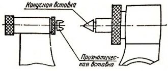
The walls of the hole should be cleaned of foreign contaminants. This can be done with a metal brush or by blowing it with air. The workpiece must be securely fixed. The tap must be installed in the hole strictly parallel to its axis. For high-quality centering in the hole when drilling, a chamfer is usually made at 30 or 45 degrees. The parallelism of the axes of the tap and the hole is checked using a square, which is applied to the surface of the tool and the edge of the part. Then the thread is cut by rotating the tool clockwise (in the case of a right-hand thread). It is especially important to cut the first turns of the thread exactly.
The crank is turned gradually. Having made a full turn, the tap is unscrewed half a turn. If the applied force increases, the tap is removed from the hole and chips are removed from it. It is recommended to use lubricant during operation. This can be a special lubricant, for example, a paste based on fats and wax, which is applied directly to the instrument. A replacement can be drying oil, kerosene or machine oil. Thread cutting on a drilling machine is carried out using special taps. The cutting process itself is no different from handmade technology.
Application of the tap
Before you start threading, you need to determine the diameter of the preparation hole and drill it. To facilitate this task, a corresponding GOST was developed, which contains tables that allow you to accurately determine the diameter of the threaded hole. This information makes it easy to select the drill size.
To cut metric threads on the inner walls of a hole made with a drill, a tap is used - a screw-shaped tool with cutting grooves, made in the form of a rod, which can have a cylindrical or conical shape. On its side surface there are special grooves located along its axis and dividing the working part into separate segments, which are called combs. The sharp edges of the combs are precisely the working surfaces of the tap.
Tap: design and parameters
In order for the turns of the internal thread to be clean and neat, and for its geometric parameters to correspond to the required values, it must be cut gradually, by gradually removing thin layers of metal from the surface being treated. That is why for this purpose they use either taps, the working part of which is divided along the length into sections with different geometric parameters, or sets of such tools. Single taps, the working part of which has the same geometric parameters along its entire length, are needed in cases where it is necessary to restore the parameters of an existing thread.
The minimum set with which you can sufficiently perform machining of threaded holes is a set consisting of two taps - rough and finishing. The first one cuts a thin layer of metal from the walls of the hole for cutting metric threads and forms a shallow groove on them, the second one not only deepens the formed groove, but also cleans it.
Types of thread taps and their differences
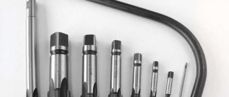
Minimum set of taps
Combination two-pass taps or sets consisting of two tools are used for tapping small diameter holes (up to 3 mm). To machine holes for larger metric threads, you must use a combination three-pass tool or a set of three taps.
To manipulate the tap, a special device is used - a wrench. The main parameter of such devices, which can have different designs, is the size of the mounting hole, which must exactly match the size of the tool shank.
Some types of tap drivers
When using a set of three taps that differ both in their design and geometric parameters, the sequence of their use must be strictly observed. They can be distinguished from each other both by special marks applied to the shanks and by design features.
- The tap, with which the hole for cutting metric threads is processed first, has the smallest diameter among all the tools in the set and cutting teeth, the upper part of which is heavily cut off.
- The second tap has a shorter fence and longer combs. Its working diameter is intermediate between the diameters of the other tools in the set.
- The third tap, with which the hole for cutting metric threads is processed last, is characterized by full ridges of cutting teeth and a diameter that must exactly match the size of the thread being formed.
Read also: How to bend an aluminum profile at 90 degrees
Set of three taps
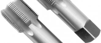
Taps are used primarily for cutting metric threads. Much less often than metric ones, taps designed for processing the internal walls of pipes are used. In accordance with their purpose, they are called pipe, and they can be distinguished by the letter G present in their markings.