The phase diagram of iron carbon can have the following phases:
- liquid phase – a solution of carbon in iron;
- solid solution of carbon in gamma iron;
- solid solution of carbon in alpha iron (delta iron);
- carbon in the form of graphite;
- iron carbide Fe3C, which is more often called cementite.
Cementite is present even in relatively slowly cooled alloys: prolonged exposure at elevated temperatures is required to decompose cementite into iron and graphite. For this reason, -carbon phase diagram
has two types: stable
iron-carbon diagram and metastable iron-cementite diagram
. They are also called “cementite system” and “graphite system”.
The phase diagram is the foundation for understanding steels
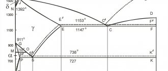
The study of the microstructure of all steels usually begins with a consideration of the metastable iron-carbon (Fe-C) phase diagram (figure). It is also called iron-cementite (iron-iron carbide) phase diagram. This diagram provides a foundation for understanding the structure and phase composition of both carbon and alloy steels, as well as the various heat treatments to which they are subjected. See, for example, the “work” of the phase diagram, or, perhaps more correctly, the phase diagram, during the crystallization of steel in the article “Cast structure of steel.”
Figure - Metastable phase diagram shows what phases can be expected in steel at various combinations of carbon content and temperature. It is sometimes called the iron-cementite phase diagram.
Properties of commercially pure iron
Magnetic properties of iron at different temperatures:
- less than 768° C – ferromagnetic;
- more than 768° C – paramagnetic.
And the temperature point of 768° C is called the magnetic transformation point, or the Curie point.
Properties of technically pure iron:
- hardness – 80 HB;
- temporary resistance - 250 MPa;
- yield strength – 120 MPa;
- relative elongation 50%;
- relative narrowing – 80%;
- high modulus of elasticity.
Solubility of carbon in austenite and ferrite
At the low-carbon left end of the metastable iron-carbon diagram we see ferrite (alpha iron), which has a maximum solubility of 0.022% at 727°C, and austenite (gamma iron), which dissolves 2.11% carbon at 1148°C. It can be seen that the austenite (gamma iron) region is much larger compared to the ferrite (alpha iron) region. This clearly indicates a significantly higher solubility of carbon in austenite with a maximum of 2.11% at 1148 °C.
The strengthening of carbon steels, like many other steels, is based precisely on this difference in the solubility of carbon in alpha iron (ferrite) and gamma iron (austenite).
On the carbon-rich side of the metastable Fe-C diagram we find cementite (Fe3C). Of less interest, with the exception of high-alloy steels, is delta ferrite at the highest temperatures.
Classification of iron-carbon alloys
Various combinations of these elements lead to a large number of alloys, which can be divided into three large groups:
- Technical hardware.
- Become.
- Cast iron.
Technical hardware
Technical iron includes materials containing less than 0.02% carbon. Steels include materials in which carbon is in the range from 0.02 to 2.14%. And the cast iron group includes materials in which the amount of carbon exceeds 2.14%.
Single-phase diagram areas
The vast majority of steels have only two allotropic forms of iron:
- alpha iron with a body-centered cubic (bcc) atomic lattice and
- gamma-iron with a face-centered cubic (fcc) atomic lattice.
At room temperature, bcc ferrite is stable from a temperature of 912 °C (point A3), at which it transforms into fcc austenite. Austenite transforms back into ferrite at a temperature of 1394 °C (point A4).
This high temperature ferrite is called delta ferrite, even though its crystal structure is identical to that of alpha ferrite. Delta ferrite remains stable until it melts at 1538°C.
Heat treatment of steels at KVADRO LLC
Our company has been producing custom heat treatment of metals in St. Petersburg for almost a quarter of a century. You can order heat treatment from us by leaving your request by email or calling us.
We carry out heat treatment of steels (including stainless steel, tool steel, etc.) according to the Customer’s drawings or specified conditions, as well as other metals and alloys (aluminum and titanium, brass and bronze, etc.).
The main types of heat treatment of metals carried out at our enterprise to order:
- hardening (including in salt baths, for example, for hardening high-speed cutters);
- vacation;
- annealing;
- normalization;
- improvement;
- cementation.
We also remind you that with us you can use a wide range of metalworking methods, including milling and turning.
Critical temperatures of steel
The most important boundaries of single-phase regions have special names. They include (in international notation):
- A1 – eutectoid temperature, which is the minimum temperature for austenite;
- A3 – low-temperature boundary of austenite at low carbon content (the boundary between the “gamma-iron” and “gamma-iron + ferrite” regions);
- Acm is the opposite boundary of the austenitic region at high carbon content (the boundary between the “gamma-iron” and “gamma-iron + cementite” regions).
Sometimes the letters c, e and r are added to the designations of these temperatures, for example, Ac1, Ac3 and Accm. The letter c indicates that phase transformations occur during heating, the letter e indicates phase equilibrium, and the letter r indicates cooling.
Stable iron-graphite diagram
This diagram is also called “graphite”. At very low cooling rates, carbon in the form of graphite can crystallize directly from the liquid phase. In this case, a eutectic mixture of austenite and graphite is formed instead of the eutectic austenite and cementite. As shown in the diagram, the dashed lines that belong to the iron-graphite system pass at higher temperatures than the corresponding lines of the iron-cementite system. This indicates greater stability and proximity to complete equilibrium of the iron-graphite system. This conclusion is also supported by the fact that heating high-carbon steels with a high content of cementite leads to its decomposition: cementite -> iron + graphite.
At moderate cooling rates, part of the alloy can crystallize according to the “graphite” phase diagram, and the other part according to the “cementite” phase diagram.
The phase equilibrium lines in the diagrams of both systems can shift depending on specific cooling rates. The most noticeable shift can be seen for the carbon evolution lines in the gamma-ray solid solution. Therefore, the diagram is only truly correct if the alloys are cooled very slowly.
Eutectoid pearlite
The carbon content at which austenite has a minimum temperature is called the eutectoid content (0.77% carbon by mass for the case of a metastable phase diagram). The mixture of ferrite and cementite phases with this carbon composition, which is formed during slow cooling, has a characteristic lamellar structure called pearlite. Pearlite is a collection of alternating plates of ferrite and cementite. These plates, after being held at a temperature close to A1, are coarsened (“spheroidized”) into cementite particles distributed in a ferrite matrix.
Educational materials
The components of this system are iron and carbon. Iron is a silver-white metal, atomic number 26, atomic weight 55.85, atomic radius 1.27 Å, melting point 1539 0C, density 7.86 g/cm3. Iron has low hardness and strength: НВ80, sв = 250 MPa, d = 50%, j = 80%; has three polymorphic modifications Fea, Feg and Fed.
Carbon
- non-metallic element, atomic number 6, atomic radius 0.77 Å, atomic weight 12.01, melting point 3500 0C, density 2.5 g/cm3. Carbon is polymorphic. It can form three crystallographic forms: graphite, diamond, fullerene.
Carbon is soluble in iron in liquid and solid states; with iron it can form a chemical compound - cementite.
There can be four phases in the Fe-C diagram:
1) liquid phase (L); 2) ferrite (F); 3) austenite (A); 4) cementite (C).
Liquid phase - exists above the liquidus line. Iron dissolves carbon well, forming a homogeneous liquid phase.
Ferrite
— solid solution of carbon intercalation in Fea.
Carbon is located in the a-Fe lattice in the center of the cube face. Maximum solubility reaches 0.02% C at 727 0C. At room temperature, it dissolves to a maximum of 0.006% C. The hardness and mechanical properties of ferrite are close to the properties of technical iron.
Austenite
- solid solution of carbon intercalation in Feg.
The carbon atom is located at the center of the unit cell. The limiting solubility of carbon in g-Fe is 2.14% at 1147 0C and 0.8% at 727 0C.
Cementite
- a chemical compound of iron with carbon Fe3C.
Cementite contains 6.67% C. It has a complex orthorhombic lattice, the unit cell of which contains 12 iron atoms and 4 carbon atoms. The melting point of cementite is not precisely determined and is about 1500 0C. Cementite has a very high hardness - about 800 HB, and is brittle. Up to 217 0C it has weak ferromagnetic properties. Based on the moment of formation in the alloy, cementite is conventionally divided into primary (CI) - crystallizes from the liquid phase, secondary (CII) - precipitates from austenite, tertiary (CIII) - precipitates from ferrite.
Cementite is an unstable compound and, under certain conditions, decomposes to form free carbon in the form of graphite.
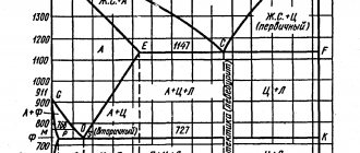
The tutorial discusses a simplified “Fe-C” diagram without the high-temperature section of the peritectic transformation (Figure 29).
Lines on the diagram:
ASD - liquidus; AECF—solidus; SE—line of limiting solubility of carbon in austenite; PQ—line of limiting solubility of carbon in ferrite; GS - line of the beginning of secondary recrystallization (during cooling) - austenite into ferrite; РG—line of the end of secondary recrystallization; S—eutectoid point; РSК—line of eutectoid transformation; C—eutectic point; ECF - eutectic transformation line.
Alloys on the chart:
- up to 0.02% C - technical iron (ferrite);
- up to 2.14% C - carbon steels;
- over 2.14% C to 6.67% C - carbon cast iron;
- from 0.006% C to 0.8% C - hypoeutectoid steels;
- 0.8% C - eutectoid steel;
- over 0.8% C to 2.14% C - hypereutectoid steels;
- from 2.14% C to 4.3% C - hypoeutectic cast irons;
- 4.3% C - eutectic cast iron;
- over 4.3% C to 6.67% C - hypereutectic cast iron;
- 6.67% C - cementite.
The eutectoid is a fine mechanical mixture of two phases - ferrite and secondary cementite (F+CI) and is called pearlite (P). The eutectoid is formed with a strictly defined amount of carbon in the alloy - 0.8%. The eutectoid transformation (during cooling) occurs at a constant temperature (727 0C):
Figure 29 — Diagram of the state of alloys of the “iron-carbon” system and cooling curves
Eutectic
is a fine-grained mechanical mixture of two phases - austenite and primary cementite (A + CI) at 1147 0C and is called ledeburite (L). The eutectic transformation occurs at a constant temperature (1147 0C), when the liquid phase has a strictly defined carbon content - 4.3%:
Phase transformations in alloys during cooling can be traced along the cooling curves.
Alloy I
contains 0.8% C and is eutectoid. Crystallization of austenite begins at point 1 and ends at point 2. Until point S, no phase transformations occur in the alloy: the alloy simply cools. At a temperature of 727 0C (point S), all austenite turns into pearlite. After the eutectoid transformation, ferrite contains 0.02% C.
As it cools, its carbon content decreases to 0.006%. Excess carbon goes to the formation of tertiary cementite (CIII). The structure of steel at room temperature is pearlite. Due to the small amount in the alloy, tertiary cementite is not indicated in the diagram.
Alloy II
is hypereutectoid. From point 3 to point 4, austenite crystallizes. At point 4, crystallization is completed, and the alloy is cooled without phase transformations to point 5, which corresponds to the limiting solubility of carbon in austenite.
As it cools, the carbon content drops to 0.8%. Excess carbon goes to the formation of secondary cementite (CII). At a temperature of 727 0C, the eutectoid transformation occurs (point 6). As a result of cooling the alloy to room temperature, tertiary cementite (CIII) is formed. The steel structure is pearlite and secondary cementite (located along the boundaries of pearlite grains).
Alloy III
is eutectic cast iron and contains 4.3% C. When the alloy is cooled at a temperature of 1147 0C (point C), the entire liquid phase turns into ledeburite, in which austenite contains 2.14% C. As cooling occurs, the carbon content in it decreases to 0. 8 %. Excess carbon forms secondary cementite. At point 7, the eutectoid transformation occurs, and below, as cooling occurs, tertiary cementite (CIII) is formed. The change in the phase composition of the eutectic alloy occurs according to the scheme
The structure of eutectic cast iron is ledeburite.
Alloy IV
is a hypereutectic alloy. From point 8 to point 9 there is crystallization of primary cementite (CI). At point 9, the liquid phase reaches the eftectic concentration (4.3% C) and the eutectic transformation occurs, ledeburite is formed. The transformation of ledeburite to room temperature is similar to alloy III. The structure of the alloy is needles of primary cementite and ledeburite.
All carbon cast irons have a crystallization end temperature lower than carbon steels, since they contain eutectic (ledeburite). This determines the high casting properties of cast iron (fluidity, low shrinkage and low tendency to absorb gases) and the lack of ductility due to the high content of cementite.
The microstructure of iron-carbon alloys is shown in Figure 31.
Critical points on the Iron-Carbon diagram > Continue >
conclusions
It is impossible to achieve absolute equilibrium, both physical and chemical, except under special laboratory conditions.
In practice, equilibrium can be close to absolute, but under certain conditions: a slow increase or decrease in the temperature of the alloy is sufficient, which will be maintained for a long time.
Sources
- https://FB.ru/article/340918/diagramma-jeleza-ugleroda-diagramma-sostoyaniya-sistemyi-jelezo-uglerod
- https://PokVorota3.ru/prokat/zhelezo-uglerod-2.html
- https://intehstroy-spb.ru/spravochnik/diagramma-sostoyaniya-zhelezo-uglerod-2.html
- https://NiceSpb.ru/materialy/diagramma-zhelezo.html
- https://pressadv.ru/stali/zhelezo-uglerod.html
- https://wiki2.org/ru/%D0%94%D0%B8%D0%B0%D0%B3%D1%80%D0%B0%D0%BC%D0%BC%D0%B0_%D1%81 %D0%BE%D1%81%D1%82%D0%BE%D1%8F%D0%BD%D0%B8%D1%8F_%D1%81%D0%BF%D0%BB%D0%B0%D0 %B2%D0%BE%D0%B2_%D0%B6%D0%B5%D0%BB%D0%B5%D0%B7%D0%BE-%D1%83%D0%B3%D0%BB%D0% B5%D1%80%D0%BE%D0%B4
- https://generator98.ru/raboty-so-stalyu/tablica-zhelezo-uglerod.html