Guides are an important part in the design of a milling machine. Many craftsmen can make CNC guides with their own hands; most practitioners have experience working at home.
When planning home furniture production, it is necessary to maintain precision in design. Therefore, many masters mastering it need high-quality equipment. A special woodworking mechanism will make work easier and allow you to create high-quality products in a short time.
To ensure that products are highly accurate but meet modern specifications, CNC models are used.
Computer numerical control
Numerical program control provides such an opportunity, but not every entrepreneur can buy it. It is for this reason that there is a need to manufacture a home-made unit, for the construction of which parts of our own production are used.
The main parts of milling machines designed for processing a particular material are guides. They are ball or roller bearings whose purpose is to move the carriage. Their goal is to speed up, simplify and add precision to production.
Types of linear guides
Linear guides come in two types:
- with ball circulation;
- with circulation of rollers.
Ball guides are made in two, four and six rows. They are miniature, suitable for use in limited installation space. Linear guides are manufactured with different drives. Among them, the most common are a toothed belt or a ball screw drive (ball screw drive).
Roller guides are made in the form of cylindrical guides and guides with a flat cage.
All guides must have the following main properties:
- low friction;
- high efficiency;
- smooth linear movement;
- ability to maintain operating parameters.
Main functional purpose
Various types of sliding door guides must ensure the free closing and opening of sliding doors, regardless of whether they are interior doors or cabinet doors. The basis of any design is the rails along which the doors move horizontally using rollers.
Additional accessories include:
- roller hangers or supports;
- profile seals and plugs;
- clamps;
- small fittings;
- additional devices, the availability of which depends on the specific choice of rollers and guides.
- "SLIDER-Volkhovets",
- "Framir"
- "Herkules" or "Rollan".
So are imported ones, the price of which is quite high:
- "Raumplus"
- "Francco"
- "Archie"
- "Hangroller"
Linear Motion Modules
Recently, in connection with the development of automation, the use of linear motion modules, which consist of:
- durable supporting profile;
- precise guiding system;
- durable drive mechanism;
- Servomotor with easy control.
In such a modular component, guides with both ball bearings and roller bearings are used. The working drive is carried out using a linear motor, toothed belt or ball screw mechanism.
Linear tables have also found their application, used when it is necessary to move large masses along axes. Due to their dimensions, they absorb large moment loads. Linear tables use:
- linear motion bushings;
- guides with ball circulation.
Igrek
Let's move on.
The cross beam on which the Y-axis rails will be installed is 510 mm long. For the purpose of unification, we will make it from the same aluminum box 80x40x4 mm. We will place the rails directly on the ends of the beam.
A large rectangular hole on the wide edge of the profile will accommodate the motor axis with a gear mounted on it. On the opposite side of the beam there will be a carriage Z. That is. the beam should pass as if through the Y carriage. To do this, we will put two identical parts on ball blocks, made from sections of a standard aluminum channel 60x40x5 mm.
We will carry out the wiring of the toothed belt in exactly the same way as along the X axis, only we will make devices for fastening and tensioning the belt at the corners.
The belt is well protected from chips and dirt. At the bottom of the profile (inside) there will be a cable loop from the Y and Z motors. All that remains is to put the plugs on the ends of the beam and that’s it.
On the front side (from the side of the Z carriage) the beam has no holes, which is very good, because This is where the chips fly. As you can see, the beam with the Y carriage turned out to be very simple.
Stiffness and preload
During operation, profile rail guides are subjected to elastic information due to the applied load. Indications of the amount of deformation depend on the types of rolling elements. But one way or another it becomes smaller when the load increases.
To increase the rigidity of the system, preload is applied. It reduces the life of linear guides by causing internal stress in them, but is capable of absorbing deformation loads when the linear guide is operated under severe vibration or shock loads. Due to the fact that preload causes elastic deformation of bearings, they become dependent on the negative influence of installation errors. This suggests that more attention should be paid to the precision of the mounting surface.
Types of preload:
- normal - used in the presence of minor vibrations;
- light - used in the presence of light vibrations and light torque;
- medium - used for shock loads and strong vibrations, as well as for overturning loads.
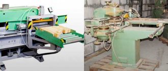
Homemade tabletop mini sawmill
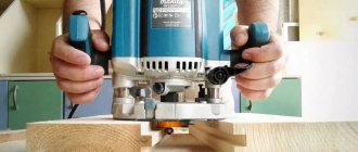
A hand-held circular saw is a must-have tool in the home workshop of a self-respecting owner. To work successfully, it must have a circular saw guide bar. Saw blades are of considerable importance; the quality and accuracy of cutting depends on their thickness and the size of the teeth. The smaller the tooth, the cleaner the surface being processed will be.
A well-equipped workshop has hand-held power tools that have a circular saw guide bar, made and set up for successful work. As well as a special connection for a vacuum cleaner and bags or containers for sawdust. This is a very practical solution, because during long sawing you won’t have to stop every minute to clean the work area. This saw is produced by Bosch for professionals. In addition, it has the ability to adjust the angle of deviation from the vertical and the cutting depth.
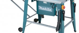
Choosing the right tool
Before purchasing, you should make sure that the selected tool provides the required cutting depth vertically and at an angle. An additional aspect that can make normal operation easier is the length of the cable. If conditions are not favorable for using an extension cord, you should choose a saw with a long cord.
The saws offered by well-known manufacturers are equipped with a device for easy replacement of discs, which further simplifies the work. This is an excellent electric tool that can be used for minor repairs around the house or garden.
Installation of rail guides
It is important to know that linear rail guides are subject to force and torque. For them, the following values must be determined: permissible static moment and load capacity, which are calculated using formulas. When calculating the nominal life of ball and roller guides, it is necessary to use different formulas.
With a constant stroke length and frequency of movements, the service life is expressed in terms of time. With compact mounting dimensions, profile rail guides have a high load capacity. Installed in various types of machines or other equipment, they are mounted in two different ways: as a horizontal rail and as a side mounting method.
Since the set consists of two parallel rails, the first rail is located on the base side, and the other on the adjustable side.
When working with large shock loads and vibrations, installing additional side parts - a side pressure plate, set tension screws, a conical wedge - helps eliminate them.
Installation of additional clamping parts when working with low loads and low speeds of movement is not necessary.
Device manufacturing algorithm
First you need to measure the diameter of the tool. Before doing this, be sure to remove the nut that holds the drill. Then apply the obtained data to the neck of the bottle and cut out a circle. For safety and convenience, you can also sand the edges of the bottle. Next, you need to insert the cap into the bottle until it fits completely and glue it with glue. This device will be very primitive and its design features will not allow the instrument to be moved vertically. But it is very cheap and very easy to manufacture.
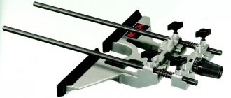
There are also more complicated ways. To implement this we need a smooth wooden board, metal rods and springs.
The first step is also to take measurements. The next step is to make wooden parts. Make two rounded rectangles and make holes in them. The first will be for the instrument itself.
And others must be placed in the corners of a wooden rectangle. We place metal rods in them, they will serve to move the drill vertically. We put springs on the rods and fix the mechanism with glue.
This device is already more functional, because it allows you to move the tool vertically.
Linear guides for CNC machines
What makes up a linear motion system? This is a combination of gear and linear guides.
Linear guides for CNC are linear bearings, guide bushings, shafts. The guides themselves must solve three main tasks:
- be a support for completing the machine;
- with minimal friction, with the required accuracy along a given trajectory, ensure the movement of machine parts;
- accept the loads arising during the work process.
Linear guides are divided depending on the method of attachment to the machine. These are guides that provide full support - the method of attachment to the frame along the entire length of the guides, and partial support - the method of end attachment.
Fully supported rails have a higher load capacity than partially supported rails. Sometimes there are options when linear guides are installed along the axes - both with full and partial fixation.
Representatives of this group are linear cylindrical guides. They make it possible to use several types of cylindrical guides:
- polished guide shafts - the most common (high availability, ease of installation);
- splined shafts – high wear resistance and rigidity, the ability to accept torsional forces from the bushing. Used for end mounting of guides;
- the shafts on the support are cylindrical rails. They are used as direct attachment to the machine.
Polished shafts
They are characterized by affordability and ease of installation, which reduces repair costs. They are not recommended for use as guides for moving tables whose flow exceeds 1 m, since fastening to the frame at two points leads to sagging under loads. At the same time, they are suitable for moving the spindle along the Z axis, provided that the spindle is not loaded (engraving, cutting thin sheet metal, wood carving, etc.) and is balanced by a counterweight.
Flaws:
- when using rolling bearings, pressure from the ball is applied at one point, and over time a groove is pressed at this point;
- increased sensitivity to chips and dust;
- impossibility of fitting the bearing to the shaft and creating preload.
However, these disadvantages are offset by the low cost and ease of replacing the shaft, and the problem of dust and shavings in wood and stone processing workshops is solved by installing a hood with a socket directly in the work area.
Mounting surface accuracy
Profile rail guides are installed using fastening on a machined base surface. The fastening method consists of creating a shoulder on the seating surface and placing the base surface or carriage on it. It is possible to avoid distortions if there is a groove in the corner of the bead itself.
There is a direct relationship between rail surface accuracy and moving accuracy. The accuracy of all equipment will depend on this. In this case, the accuracy of the processed mounting surface necessarily corresponds to the specified movement accuracy. It is important to remember that it is necessary to take into account the flatness of the block, while eliminating the deformation of the carriage.
Installation procedure
Installation of rails (Hiwin and other brands)
Before installing the guide, clean the supporting surface from burrs and dust. Note. Because the guide is coated with anti-rust oil, before using the guide, remove the oil from the base surface by wiping it with absorption oil. After removing the anti-corrosion oil, the base surface remains unprotected from corrosion
It is recommended to coat it with low viscosity spindle oil. Carefully place the rail on the support surface and temporarily secure it with bolts so that the rail is lightly pressed (align the mark on the rail with the side reference surface of the support). Note. In order for the installation of rail guides to proceed correctly, at this stage the guide must be secured
Clean bolts should be used to secure the guide. When installing bolts into rail mounting holes, check that the holes are not misaligned. Forcibly tightening a bolt in an offset hole may degrade the guide's accuracy.
Tighten the rail mounting screws in order to a torque sufficient to press the rail firmly against the side support surface. Tighten the mounting bolts to the specified torque using a torque wrench (see Table 1) Note. To ensure consistent accuracy when tightening the rail mounting screws, tighten them in order from the middle to the ends of the rail.
Install the second rail in the same way. This completes the installation of the rails. Drive the plugs into the bolt holes on the top surface of each rail so that the plugs are flush with the top surface of the rail.
Installation of carriages
Carefully place the table on the carriages and temporarily secure it with the mounting bolts. Press the carriages on the main rail side to the side base surface of the table using the locking bolts and install the table in place. Fully tighten the installation bolts on the main and auxiliary sides. This completes the installation
Note To secure the table evenly. tighten the installation bolts diagonally
This method saves time and ensures the straightness of the rail, and also avoids machining of the locating pins, which significantly reduces the labor intensity of installation.
Example of installing a guide when the main rail does not have mounting screws
- Main Rail Installation After temporarily tightening the installation bolts, press the rail firmly against the side base surface at the location of each installation bolt using a small vise, and then fully tighten each bolt. Tightening is carried out in order from one end of the rail to the other.
- Installation of the auxiliary rail To install the auxiliary rail in parallel with the main one, which is already correctly installed, we recommend using the methods described below. Using a Ruler Place the rulers between the two rails parallel to the side reference surface of the main rail using an indicator head. Then tighten the installation bolts in order while maintaining the straightness of the auxiliary rail, using the indicator head and ruler as a reference.
Using Parallel Table Edges Secure the two carriages to the main rail using a table (or temporary measuring table), and temporarily mount the rail and carriage to the auxiliary rail using a table. Place the indicator head on the side of the auxiliary rail carriage. In this case, the head holder is fixed on top of the table. Then tighten the bolts in order, keeping the auxiliary rail parallel by moving the table toward the end of the rail.
Installing the Sub Rail on the Main Rail Place the table on the carriages of the properly installed main rail and temporarily secure the sub rail, then fully tighten the installation bolts of the two carriages on the main rail and one of the two carriages on the sub. Fully tighten the bolts on the auxiliary rail in order when temporarily securing the second carriage to the auxiliary rail
Using a conductor Using a device similar to that shown in Fig. below to ensure parallelism of the base surface on the auxiliary side relative to the side base surface on the main side is carried out from the end of the rail in the direction of travel in accordance with the pitch of the rail. At the same time, the bolts are fully tightened in the correct order.
Ready!
The installation of HIWIN rails (or the installation of other brand rails) is complete.
Corrosion protection and lubrication
To protect the guides from corrosion, they are made of stainless steel. There is an option with the application of a special protective coating. Its use is carried out when a high degree of corrosion protection is required.
The finished factory guides are lubricated with lithium soap-based grease. After this, they can be used for their intended purpose. Different operating conditions will require the desired frequency of adding the same type of lubricant.
Axle preparation
Preparing the axle is the main secret. The axle must be prepared so as not to damage the rather delicate interlayer material. Even the skin can easily suffer from the slightest burr on a metal axle. The rag will wipe off instantly. Previously, strong round wooden shafts were used as cart axles. Wood is a good material for such axles, as it is quite easy to polish, and it is quite soft, so it is additionally polished in the bearing itself on a leather spacer.