LLC SO "PRESSMASH" produces and sells open-type crank presses. The equipment is designed for processing sheet metal using the cold stamping method. The following operations can be performed on open crank presses:
- flexible,
- pruning,
- hole punching,
- shallow hood,
- cutting down and a number of other actions.
The functionality of this equipment allows the production of parts of various shapes - from simple plates and disks to stepped shafts. Stamping equipment allows you to give workpieces a certain shape. An open crank press is one of the most popular categories of equipment used in metalworking.
We will advise you on any questions!
Have a question?
Our services
Machines for performing forging and stamping operations (or rather, because some equipment is usually created for the developed technology, and not vice versa) are a common type of device for metalworking.
For example, in machine- and instrument-making enterprises or factories for the production of metal structures, for every 5 metal-cutting machines there is necessarily one piece of equipment for pressure processing. And not only metals: for example, the same PET bottles are produced on injection molding machines, which are also specialized stamping equipment.
Information about the manufacturer of the single-crank press KD2124
The developer of the single-crank press KD2124 is the Azov Special Design Bureau of Forging Equipment and Automatic Lines, SKB Co.
The KD2124 press was produced at the following factories:
- Salsky plant of forging and pressing equipment , Salsk
- AKMA, Astrakhan Machine-Building Plant KPO , Astrakhan
- Leninakan plant KPO Leninakan (Gyumri)
Currently, the KD2124 press is produced by:
- Dolina, PJSC Kuvandyk plant KPO, Kuvandyk, Orenburg region.
- PressMash, LLC Machine Tool Association, Moscow
- PressKomplekt, LLC Salsk, Rostov region.
- PromStroyMash, LLC Orenburg
- Construction machines, LLC St. Petersburg
- YuUMZ, LLC Uzhno Ural Mechanical Plant, Kuvandyk
- Stankogid, LLC Orenburg
Machines produced by the Salsky Forging and Press Equipment Plant
- KD2122
- open single-crank press 160 kN - KD2124
- open single-crank press 250 kN - KD2126
- open single-crank press 400 kN - KD2128
- open single-crank press 630 kN - KD2322
- single-crank, single-action, tilting press 160 kN - KD2324
- single-crank, single-action tilting press 250 kN - KD2326
- single-crank, single-action, tilting press 400 kN - KD2328
- single-crank, single-action tilting press 630 kN
Types of stamping technologies
The stamping process of processing blanks can be carried out using the hot or cold method. These technological varieties involve the use of special equipment and the use of certain metal processing conditions.
Cold stamping is one of the types of stamping
The hot stamping method processes workpieces that are preheated in special devices to a given temperature. Hot stamping is necessary when there is not enough equipment power to process a cold alloy. Heating devices can be electric or plasma ovens. This method requires accurate calculation of the parameters of the finished part, taking into account the shrinkage of the metal during the cooling process.
In cold stamping, parts are formed due to the mechanical pressure of the elements of the stamping press. Cold stamping is considered a more common method of metal processing. It does not require additional equipment, complex calculations or mechanical modification of parts. Thanks to this method, the strength properties of the material increase. The resulting products are distinguished by high surface quality and precision.
Overall dimensions of the working space of the K2130 press
Overall dimensions of the working space of the K2130 press
Installation dimensions of single crank press K2130
Evolution of equipment development
Until the 15th and 16th centuries, almost all metal products were produced by private workshops and small workshops. However, the beginning of the Great Geographical Discoveries with the accompanying increase in the tonnage of sea vessels required the production of fairly large anchors and other ship equipment. It was no longer possible to forge such large parts by hand with a hammer. As a result, the first mechanical hammers powered by water power appeared.
Further, the impetus was the development of weapons and vehicles, and in the 19th century entire metalworking giants with steam equipment emerged.
The invention of hydraulic presses made it possible to introduce stamping as the main technology for mass production of products. And the further emergence of electric motors gave impetus to the development of crank presses, which form the modern basis of forging and stamping equipment.
Making a diagram of the press
The simplest scheme that implements the desired algorithm may look like this:
The simplest diagram of a crank press
What does it remind you of? Yes, this is a classic self-retaining circuit, which is widely used to start electric motors. I decided not to indicate the neutral wire of the sensor so as not to clutter the diagram. I did not show the power, emergency and supply circuits - I have already written on this issue on the blog more than once.
The sensor contacts are equivalent to the “Stop” button, SB is a pedal, or 2 consecutive buttons on the panel. Relay KA1 has 2 groups of contacts - one for self-retaining, the other for turning on the electromagnet of the EM pneumatic valve.
The operation of a self-retaining circuit can be represented as a trigger, since when you briefly press Start, it is armed, i.e. Start = Set, Stop = Reset, KA1 = Q (output).
Pressing the SB pedal - the KA relay turns on, becomes self-retaining with its KA contacts, and remains on until the sensor opens the relay power circuit. This may take several strokes while the operator keeps the pedal pressed. When the pedal is depressed, the shock cycle will end at the top point, at the point where the sensor crosses zero.
When a full revolution is made, the sensor is deactivated, KA1 is turned off, the sensor activator rotates by inertia, and the sensor is activated so that a new pressing cycle can begin.
To prevent the valve from clicking when crossing zero, the KA1 contacts, which turn on the EM, can be bypassed with NO pedal contacts. Since the pedal, as a rule, does not have such contacts, you need to install an intermediate relay.
We continue to improve the scheme. In order to be able to continuously rotate the flywheel, the sensor can be bypassed. Then, when you briefly press the pedal, the EM will turn on and will remain on until the continuous mode is turned off:
Add switch SA1 to the circuit
This is the diagram I stopped at, only the sensor is connected via an intermediate relay.
There is also an interesting and necessary feature in the setup mode - when you turn on this manual mode, you can make the engine turn off. Then you can manually turn the flywheel in one direction or the other. This is useful in emergency situations when the press punch gets stuck in the down position. This can happen in different cases - jamming of a part, loss of air (more precisely, a decrease in pressure), and getting your hand under the press. Unfortunately, all these cases in mass production are not uncommon...
We continue to complicate things. We introduce another relay KA2, which allows you to work in the “1 press = 1 hit” mode. This mode is needed for safety and does not allow the operator to get too carried away.
Press diagram with a limit of 1 hit
The right side of the circuit remains absolutely the same, only the second NC contact of the pedal serves as an “anti-self-retaining” - if the pedal is pressed, it is open, and when the sensor opens at the end of the cycle, relay KA2 turns off.
This mode is turned off by toggle switch SA2.
Types of stamping equipment
To produce products from sheet metal, presses equipped with various stamps are used. During operation of the equipment, the upper component of the die moves, the lower part remains stationary.
Deformation of the workpiece occurs at the moment of contact between parts of the equipment. There are various models of stamping presses, which allows you to choose the right machine to produce the required parts.
Hydraulic Punching Machine
Presses for metal stamping are:
- crank type;
- hydraulic;
- radial forging type;
- electromagnetic type.
Crank presses are a simple type of equipment and can be double or triple acting. The presses got their name from the crank mechanism, which is the main structural element of the machine. The principle of operation of the mechanism is based on the transformation of rotational motion from the drive into reciprocating periodic movement of the press element - the slide.
General view of the single-crank press KD2124
Photo of single crank press KD2124
Photo of single crank press KD2124
Photo of single crank press KD2124
Photo of single crank press KD2124
Operating principle and design of various types of presses
metal stamping workshop
Any standard stamping machine consists of the following main components: motor, transmission, actuator. The transmission and motor together make up the "drive". The main characteristic of the drive is the type of connection between the engine and the actuator: mechanical or non-rigid (liquid, gas, steam). Working parts of the press: rollers, slider, cross-beams, rollers, women.
Crank press
The machine drive rotates, the movement on the slide is converted to reciprocating. Under the influence of this movement, the metal is processed using a stamp. All machine parts are made of durable steel and equipped with stiffeners. The movement of the slider occurs according to a strict schedule. The force on the slide reaches 8 thousand tons. Crank forging plants make it possible to speed up, simplify and reduce the cost of production of parts, saving up to 30% of rolled stock. All crank machines are divided into simple, double and triple action.
The crank press is capable of performing the following types of work:
- stamping in open and closed dies;
- burr formation;
- extrusion;
- firmware;
- combined processing.
A mechanical press acts on the material with an impact, while a hydraulic press, applying less force, gets a greater effect. Therefore, the latter are used for the manufacture of large products with thick walls.
Hydraulic presses
Capable of stamping surfaces, pressing and forging metal products. They are also used for recycling metal waste. The operation of the machine is based on increasing the force of pressure on the metal many times. The press consists of two communicating cylinders with water, between which a pipe passes. Pistons are installed in the cylinders. The operating principle of the press is based on Pascal's law.
Radial forging apparatus
Processes metal using the hot method. The blank enters the heating module, which operates on the induction principle. Here it is heated, when the metal becomes sufficiently pliable, it is fed through a conveyor to a gripping mechanism, which feeds the workpiece directly into the processing zone. Forging or stamping is carried out with strikers; during the process, the workpiece rotates all the time, due to which it is processed evenly on all sides. The press is powered by an electric motor connected by a V-belt drive to the shafts. They are placed vertically and direct movement to the connecting rod and striker, between which the slider is installed. To ensure that all movements of the mechanism are synchronous, there are copying drums. The blank holder is rotated by an electric motor through worm gears. The spring clutch slows down the movement at the right moments.
Electromagnetic press
This is the latest development, which is just beginning to be used in industry. The working body of the machine is the core of an electromagnet, which moves under the influence of an electromagnetic field. The core moves the slider or die, the springs return the slider to its original position. Such machines are characterized by high productivity and efficiency. Today, there are models with a small amplitude of movement of the working body - 10 mm and a force of no more than 2.5 tons.
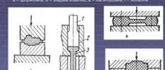
Description of individual components of the crank press KD2124
Balancer
The counterbalancer is designed to eliminate the influence of the weight of the slider and the upper half of the die on the operation of the press and to prevent arbitrary lowering of the slider in emergency cases: breakage of the adjustment screw in the connecting rod or the studs of the connecting rod cover.
By design, the balancer is a single-acting pneumatic cylinder mounted on a frame.
Rod 3 (Fig. 14) is connected to the slider bracket. The compressed air into the pneumatic cylinder 2 comes from the receiver through the hole in the bottom cover 4. The piston I by the rod 3 constantly pulls the slide up.
KD2124 crank press drive
KD2124 crank press drive
The press is driven from an electric motor 3 through a V-belt drive 5, a flywheel 6, and a brake clutch to the eccentric shaft.
The electric motor is installed on a swinging sub-motor plate 4. Rotation of the electric motor is counterclockwise (if you look at the end of the shaft from the flywheel side).
The belt tension is adjusted using screw 2 and nut I.
“Clutch-brake” device for single-crank press KD2124
Clutch brake single-crank press KD2124
The “Clutch-brake” device consists of a normalized “clutch-brake” unit UV3138, an air supply head 19 and a flywheel 12, the supports of which are radial ball bearings 17 mounted on a sleeve 18, which in turn is installed on an eccentric shaft 22.
Actually, the clutch-brake itself, a rigidly interlocked multi-disc friction with pneumatic activation, consists of the following parts:
- driving - driving disks 14 of the clutch with friction linings 15;
- driven - a hub with a fixedly attached piston 2, a cylinder 3 moving along the axis, support disks 8 mounted on the threads of the hub 21 and piston 2, a brake pressure disk 7 mounted rigidly on the cylinder, an intermediate clutch disk 16;
- brake - brake disc 10 with friction linings.
The “Clutch-brake” device works as follows: compressed air through the air supply head 19, the eccentric shaft 22 enters the pneumatic chamber 1 and moves the cylinder 3 along the axis of the eccentric shaft towards the clutch and clamps the drive disks 14 of the clutch, connected to the constantly rotating flywheel 12 through the fingers 13, ensuring the transmission of torque through the hub 21 to the eccentric shaft 22.
At the moment of braking of the eccentric shaft 22, compressed air from the pneumatic chamber is released into the atmosphere through the air supply head 19, the connecting sleeve and the three-way double interlocked valve.
In this case, cylinder 3, under the influence of springs 20, returns towards the brake and clamps the brake disc 10, sitting on fingers 11 connected to the frame 9. In this case, the moving parts of the press are braked.
Eccentric shaft of single-crank press KD2124
Eccentric shaft of single-crank press KD2124
The eccentric shaft consists of the eccentric shaft 5 itself (Fig. 11), an eccentric bushing 6, an axle box 8 and an adapter bushing 9, intended for installing mechanization equipment on the press.
The slider stroke is adjusted by rotating the eccentric sleeve 6, which engages with the shaft 5 through an involute gear and is disengaged by rotating the nut 7.
In this case, in order to avoid displacement of the connecting rod, it is necessary to insert a wooden spacer between the connecting rod and the frame axle box.
After setting the required stroke value of the slider, the eccentric sleeve 6 is engaged with the eccentric shaft 5 and locked with screws 10, and the wooden spacer is removed.
Stopping the slider at top dead center after adjusting the slider stroke is done by rotating discs 3. Discs I and 2 are designed to control the braking distance and to count strokes. The discs are pinned together and can be rotated together after loosening the bolts 4.
Slider of single crank press KD2124
Slider of single crank press KD2124
The slider is the working body to which the upper part of the stamp is attached.
Slider 3 (Fig. 12) of the press has a box-shaped shape with prismatic double-sided guides.
The slider is attached to the eccentric shaft by means of an adjusting screw 10 and a detachable connecting rod 11, in the housing and cover of which bronze plain bearing shells are installed, covering the eccentric sleeve. An adjusting screw 10 is screwed into the connecting rod from below, the ball head of which is enclosed between the lower support 5 and the upper floating liner 6.
The ball head, support and floating liner are placed in the cup 4. After adjusting the gap in the ball joint, the nut 8 screwed into the cup is locked with a key 19. The support of the cup 4 is a shear safety washer 22, designed to be destroyed when the press is overloaded. The safety washer is installed on the wedge mechanism 2 for removing the press from the expansion. When cutting off the safety washer, it is necessary to lift the connecting rod with the adjusting screw and the sleeve by rotating the press flywheel in the “Manual crank” mode, replace the safety washer, lower the connecting rod with the adjusting screw 10 and the sleeve 4 to the original position, tighten the nut 9 and lock it with screw 20.
The size of the stamping space is adjusted by rotating the adjusting screw by its hexagon using a wrench. Before this, it is necessary to adjust the pressure in the pneumatic network using a pressure regulator within the range of 1.5...2 kgf/cm2 to ensure ease of turning the adjusting screw.
The established size of the die space is fixed by locking bushings 15 and 16, which are pulled back by screw 17.
The lower limit of die space adjustment is limited by clamp 14.
The amount of adjustment is determined by ruler 12.
At the bottom of the slide there are holes for fastening the upper die plate and a hole for the shank of the upper die plate.
The shank is fastened with clamp 23 using two studs with nuts.
The locking screw 31 serves to push away the clamp when removing the stamp. The ejector rocker arm I is located in the groove of the slider. The stops for the rocker arm are height-adjustable stops 7, mounted on the frame.
Locking bushings 15 and 16 are kept from turning by screws 18.
Pneumatic diagram of single-crank press KD2124
Features of open and closed dies
Closed stamping
Stamping equipment can be equipped with open or closed dies. In an open die, excess metal flows into a burr or flash that performs a specific function. The main disadvantages of this technology are: loss of alloy due to flash, reduction in product quality due to cut fibers when removing burrs.
Closed dies are used to produce simple shaped products. This flash-free technology is characterized by metal savings, no costs for cutting burrs, and high product quality due to all-round compression. Metal fibers are not cut. The closed die processing method is used for low-plasticity alloys. The main disadvantages are: the need for precise dosage of the alloy, the complex design of the die.
In modern manufacturing, stamping is primarily a preparatory operation that allows the production of parts for both electronics and aircraft or watercraft. The resulting products are subsequently subjected to welding, cutting, riveting and other processing methods depending on the technological process.
Download files
If you want to know how relay circuits are compiled in science, download an interesting book:
• Logical techniques for compiling and analyzing relay-contact and non-contact circuits / Guidelines (manual) for practical classes in the course “Automated control systems” Direction 220300 - Automated technologies and production , pdf, 304.8 kB, downloaded: 965 times./
Splan file, in which I made the diagrams for this article:
• Press CD / Schemes in SPlan format., zip, 16.7 kB, downloaded: 1235 times./
Overview of IPONMAC presses and their characteristics
| Model series | KD 23D | HL41 | PG41 |
| Nominal force, t | 10-80 | 40-315 | 40-315 |
| Opening height/clearance, mm | 130-280 | 800-1600 | 800-1600 |
| Table/bottom plate size, mm | up to 520*860 | up to 1400*1200 | up to 1400*1200 |
| Drive power, kW | 1,1-7,5 | 5,5-30 | 5,5-30 |
| Weight, kg | 600-5280 | 3000-36000 | 3-36000 |
Values of the main parameter in the designation of presses:
Table 1. Designation of the main parameter of the press
| Press designation | Press force, kN | Press designation | Press force, kN | Press designation | Press force, kN | Press designation | Press force, kN |
| 14 | 25 kN | 20 | 100 kN | 30 | 1000 kN | 40 | 10000 kN |
| 15 | 31.5 kN | 21 | 125 kN | 31 | 1250 kN | 41 | 12500 kN |
| 16 | 40 kN | 22 | 160 kN | 32 | 1600 kN | 42 | 16000 kN |
| 18 | 63 kN | 23 | 200 kN | 33 | 2000 kN | 43 | 20000 kN |
| 24 | 250 kN | 34 | 2500 kN | 44 | 25000 kN | ||
| 25 | 315 kN | 35 | 3150 kN | 45 | 31500 kN | ||
| 26 | 400 kN | 36 | 4000 kN | 46 | 40000 kN | ||
| 28 | 630 kN | 38 | 6300 kN | 48 | 63000 kN |
Example of designation of mechanical presses:
- KD2122 - 160 kN, single-crank open press (C type), simple action, two-post with a fixed table
- KD2124 - 250 kN, single-crank open press (C type), simple action, two-post with a fixed table
- KD2126 - 400 kN, single-crank open press (C type), simple action, two-post with a fixed table
- KD2128 - 630 kN, single-crank open press (C type), simple action, two-post with a fixed table
- K2130 - 1000 kN, single-crank open press (C - type), simple action, two-post with a fixed table
Example of hydraulic press designation:
- P6320B - 100 kN, single-column press with correct pressing
- P6328B - 630 kN, single-column press with correct pressing
- P6330 - 1000 kN, single-column press with correct pressing
- P6334 - 2500 kN, single-column press with correct pressing
rice. 3. Single-acting open single-crank presses with a force of up to 630 kN
- a - non-tilting single-post with a movable table and a horn of the KD14 type
- b - the same with the horn installed;
- c - non-tiltable two-post with a fixed table, type KD21
- g — tilting two-column presses with a fixed table, type KD23
Design features
All units for processing metal workpieces have approximately the same structure. Three main nodes can be distinguished. These include:
- equipment engine;
- torque transmission;
- actuating mechanism.
The first nodes form the drive system, on which the functioning of the actuator depends. Each organ is responsible for a specific result. Therefore, you should understand what types of machines there are.
Zero protection
I already wrote about zero protection in an article about emergency circuits in industrial equipment. The main idea is that the machine should not start rotating when the power is turned on. You must first return all the mechanisms to their original state, press the ready button, and only then can you start the engines.
For example, this principle is inherent in the zero protection of lathes - when power is applied, the engine cannot be turned on until the gearbox is brought to the neutral position.
I propose a circuit that, when power is applied, checks that the pedal is not pressed, which will be indicated by the switched on relay KA3:
Zero protection circuit
When the SB pedal is briefly pressed, relay KA3 continues to remain on in self-retaining mode, and KA1 becomes self-retaining. The EM is turned on through relay contacts KA1 and KA3. When the sensor is deactivated (end of cycle), both relays are reset. Due to inertia, the sensor becomes active again, and KA3 turns on. The circuit is ready for use again.
This scheme eliminates spontaneous activation of the press in case of problems with the pedal - getting stuck, pressing with an arbitrary object.
Hydraulic and crank type stamping presses
From the moment people learned to perform metal forming, the work of the specialist who did it was considered one of the most honorable. Over time, the need for metal products obtained using forging technology only increased, and the actively developing industry began to need them. All this led to the fact that for forging, not the manual labor of blacksmiths, but special equipment for stamping was used.
A fairly common type of device used for forging is a kind of hammer analogue - a stamping press. Using such stamping equipment, it is possible to perform a whole list of technological operations, namely: changing the shape of the workpiece by means of its plastic deformation, forming a given relief on its surface, cutting out individual fragments, etc. On such a device, in particular, they give shape to the workpieces for the manufacture of which casting was used. Presses used for stamping operations can be crank or hydraulic.
Press diagrams: a – vertical hydraulic; b – horizontal; c – crank; g – friction; d – hydraulic screw
A crank press is used in cases where it is necessary to perform simple metal forming by pressure. The main element of such equipment, which converts the rotational movement of the drive motor shaft into reciprocating movement of the slider, is the crank mechanism. That is why a crank press is often called a stamping crank press. It is very popular both among manufacturers and private craftsmen; there are even models of a tabletop crank press. This popularity is explained not only by the high efficiency and functionality of this equipment, but also by the fact that maintenance and repair of crank presses does not cause any special problems.
Hydraulic stamping press 4-column
Hydraulic stamping presses are equipped with two working chambers in which the required pressure is created in the working fluid. The liquid under pressure enters the cylinder with another piston, through which reciprocating motion is imparted to the slide.
Location of the components of the single-crank press KD2124
Location of the components of the KD2124 press
List of components of the single-crank press KD2124
- Tilt mechanism - KD2324-12-001
- Drive guard - KD2324-71I-001
- Clutch-brake device - KD2324-26E-001
- Bed - KD2324-11I-001, KD2124-11I-001
- Drive - KD2324-21I-001
- Air duct - KD2324-41I-001
- Work area fencing - KD2324-73I-001
- Electrical equipment - KD2324-91E-001
- Slider balancer - KD2324-34-001
- Eccentric shaft - KD2324-23E-001
- Fencing - KD2324-72-001
- Slider - KD2324-31I-001
- Oil line - KD2324-82-001
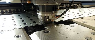
Types of technological operations
Technological operations with metal sheets are separating and forming.
Separation stamping operations are performed on equipment equipped with special tools. As a result, a certain part is separated from the workpiece along a straight line or a given contour. The separation of part of the sheet occurs in the following processes:
- Segment _ To perform this action, the equipment is equipped with disk, vibration devices or guillotine shears.
- Trimming . This operation separates the extreme parts of the resulting product.
- Punching . Holes of various configurations are created in a metal sheet using a stamp.
- Felling . A shaped part with a closed contour is obtained from the workpiece.
Form-changing operations are intended to create a product with different parameters and dimensions without mechanical destruction. The following types of these operations are distinguished:
- Beading. The contour of the workpiece or the internal holes are exposed to the stamp to form beads of certain sizes.
- Hood. This operation is a type of volumetric stamping, in which a spatial element is obtained from a flat material.
- Crimping To narrow the ends of a hollow workpiece, a stamp with a conical-type matrix having a narrowing working area is used.
- Flexible. As a result of the operation, the curvature of the surface changes by bending the metal and deforming the workpiece.
- Molding is a change in the shape of individual sections by reducing the thickness of the part without disturbing the external contour of the product.
- Puklyovka. Connecting two plates with a stamp without using additional elements.
Ladder logic
As I already said, any circuit on a relay corresponds to a circuit on logical elements. AND, OR, NOT, Delay Line, Trigger (memory cell) - all this is implemented on a relay.
Here is an interesting video that talks about this in detail:
I recommend the site pro-rza.ru for those who work with relay circuits (as well as program algorithms) professionally, and not just based on intuition). You can also find a lot of interesting information on the topic if you enter the query “relay logic circuits” in Yandex.
Radial forging equipment for hot metal processing
A radial forging machine is used to produce shafts of various diameters with high productivity. With such a unit it is possible to set up production of up to 300 thousand finished products per year, which is quite enough to supply a large manufacturing enterprise with them.
The limited use of such a machine for metal stamping is explained not only by its high cost, but also by the fact that setting up its operating modes is a rather complex process, so it is advisable to perform it only if you plan to produce products of a certain diameter in large quantities.
Radial forging machine (RFM) ensures high stamping accuracy, producing parts with minimal allowances
The sequence of actions during which radial forging is performed is as follows.
- The part is fed into an induction device to bring it to the required heating temperature.
- After the metal acquires the required degree of plasticity, the part is sent along a roller container (rolling table) to a gripping device, with the help of which it is fed into the processing zone.
- There, the workpiece is fixed by elements of another gripping device, after which it is acted upon using special strikers.
- To ensure uniform processing on all sides, the part is constantly rotated, for which a special gripping mechanism is used.
Schemes of operation of forging machines of radial and rotary type
In order to set in motion the working mechanism of equipment for radial forging, a kinematic diagram is used, the elements of which are:
- drive motor;
- V-belt transmission;
- four vertically mounted shafts with eccentric axle boxes;
- a connecting rod with a striker and a slider attached to it.
The main automatic elements of the machine are the tracing drums, which are responsible for both the synchronous approach of the strikers and the subsequent movement of the workpiece. The rotation of the grip in which the workpiece is held is imparted by an electric motor through the worm gear elements. The braking of this mechanism, which occurs during forging, is provided by a spring clutch.
One of the types of forging equipment is a horizontal forging machine, in which the workpiece is also located parallel to the ground. Devices of this type are used primarily for forming end thickenings on rod-type workpieces. During processing, the part is located in a split matrix, the channels of which are oriented in the horizontal plane.
The processing process performed on such a machine occurs in the following sequence.
- The workpiece is placed in the stationary part of the matrix.
- The moving part of the matrix, connected to the slider, is driven by the crankshaft.
- Approaching the stationary half of the mold, the movable part of the matrix tightly covers the processed rod.
- After clamping the part with the top of the mold, the crankshaft connected to the connecting rod drives the impact punches.
- At the end of processing, all moving parts of the machine return to their original position, and the moving and stationary parts of the mold are opened.
Data for building a diagram
The diagram looked like this:
Diagram of an electric press KD
The initial data is as follows.
Pedal, engine on/off buttons, manual mode on/off toggle switch (adjustment mode), two manual cutting buttons (as in a hydraulic and pneumatic press), inductive crank position sensor. These are the input elements of the circuit.
Output data - asynchronous three-phase electric motor 1.5 kW, electro-pneumatic valve at +24 V, and a little indication.
Since there was already a transformer, any control circuit will be powered through it. The option with galvanic isolation is always preferable, since the circuit will be at a low potential, and is safe when touching live parts.
Of course, candy from
Giblets inside the electrical cabinet
It won’t be possible to do this, since it’s a budget option, but I guarantee that my scheme will work reliably. At the time of writing, the press has been running for more than a year and a half, without complaints.
Air driven forging hammer
A pneumatic press is an efficient, but at the same time affordable forging equipment, which is also distinguished by its compact dimensions. This machine operates using the energy of compressed air, which is supplied to the mechanisms by a built-in compressor. The operation of the compressor, the pistons of which, moving in its main cylinder, create an air flow with the required pressure, is ensured by a drive electric motor.
Since the impact mechanism of a pneumatic forging machine is operated by a crank, its design resembles that of a crank press. Before starting such equipment, the compressor and working pistons in the master cylinder are in their highest and lowest positions. When the machine is put into operation, the pistons begin to move towards each other, compressing the air between them, the pressure of which is transmitted to the crank, directly connected to the striker. For one blow of the working part of the hammer of a pneumatic machine there is one revolution of the crank mechanism. Accordingly, in order for the hammer to act on the workpiece at a higher frequency, it is necessary to ensure more intensive operation of the compressor. Even despite its small dimensions, a pneumatic press can provide a hammer impact weight of up to 1 ton.
Pneumatic forging hammer MA-4129 is designed for hot stamping in open dies
A steam-air hammer operates on a principle similar to a pneumatic press, in which the impact energy is provided by hot steam supplied directly from the boiler or through a special compressor. The mass of impacts that such equipment allows to achieve can reach up to 8 tons, and the speed of their application is 50 m/sec. Depending on the model, it can work in automatic mode, when blows are applied to the part continuously, or in manual mode, when the corresponding button or pedal must be pressed to activate the striker.
Mechanical hammers can be used for:
- free forging or forging operations in which a mold is used to form the finished product;
- stamping operations with sheet metal parts - cutting along a straight or curved line, cutting along various contours, punching holes (punching press), etc.;
- punches - making products using a special template.
Location of controls for single-crank press KD2124
Location of press controls KD2124
List of controls for the single-crank press KD2124
- Pedal
- Button “Slider stroke” (two-handed activation)
- Button "Stop Autowork"
- "General stop" button
- Local lighting switch
- Light signaling
- Lube Pump Button
- Light signaling
- Move counter
- Operating mode switch
- Input switch
- Control circuit lock
- Machine start button