Machines for performing forging and stamping operations (or rather, because some equipment is usually created for the developed technology, and not vice versa) are a common type of device for metalworking.
For example, in machine- and instrument-making enterprises or factories for the production of metal structures, for every 5 metal-cutting machines there is necessarily one piece of equipment for pressure processing. And not only metals: for example, the same PET bottles are produced on injection molding machines, which are also specialized stamping equipment.
Types of stamping technologies
The stamping process of processing blanks can be carried out using the hot or cold method. These technological varieties involve the use of special equipment and the use of certain metal processing conditions.
Cold stamping is one of the types of stamping
The hot stamping method processes workpieces that are preheated in special devices to a given temperature. Hot stamping is necessary when there is not enough equipment power to process a cold alloy. Heating devices can be electric or plasma ovens. This method requires accurate calculation of the parameters of the finished part, taking into account the shrinkage of the metal during the cooling process.
In cold stamping, parts are formed due to the mechanical pressure of the elements of the stamping press. Cold stamping is considered a more common method of metal processing. It does not require additional equipment, complex calculations or mechanical modification of parts. Thanks to this method, the strength properties of the material increase. The resulting products are distinguished by high surface quality and precision.
This is interesting: Radial drilling machine 2M55: characteristics and documentation
Forging and stamping
From the time man learned about iron, he began to look for ways to make it stronger, more reliable and at the same time give it the desired shape. Sponge iron was beaten with cold hammers to give the metal the desired shape and remove impurities from it. Then, to make it easier to solve this problem, they decided to beat it while it was hot. This method was called hot forging.
Forging is one of the most ancient methods of metal processing. In the distant past, the tools of a blacksmith’s labor were an anvil, a hammer and simple tools: bits, chisels, smoothers, etc. In the 16th century. hammers appeared that were driven by the energy of moving water (water drive).
This made it possible to increase the mass of the hammer (falling striker) by 10-15 times - up to 400 kg. The impact force of such a hammer naturally increased significantly. With the advent of steam engines, new opportunities opened up for increasing the force of a hammer blow. Almost simultaneously with the steam locomotive, the steam hammer was born.
Evolution of equipment development
Until the 15th and 16th centuries, almost all metal products were produced by private workshops and small workshops. However, the beginning of the Great Geographical Discoveries with the accompanying increase in the tonnage of sea vessels required the production of fairly large anchors and other ship equipment. It was no longer possible to forge such large parts by hand with a hammer. As a result, the first mechanical hammers powered by water power appeared.
Further, the impetus was the development of weapons and vehicles, and in the 19th century entire metalworking giants with steam equipment emerged.
The invention of hydraulic presses made it possible to introduce stamping as the main technology for mass production of products. And the further emergence of electric motors gave impetus to the development of crank presses, which form the modern basis of forging and stamping equipment.
Types of stamping equipment
To produce products from sheet metal, presses equipped with various stamps are used. During operation of the equipment, the upper component of the die moves, the lower part remains stationary.
Deformation of the workpiece occurs at the moment of contact between parts of the equipment. There are various models of stamping presses, which allows you to choose the right machine to produce the required parts.
Hydraulic Punching Machine
Presses for metal stamping are:
- crank type;
- hydraulic;
- radial forging type;
- electromagnetic type.
Crank presses are a simple type of equipment and can be double or triple acting. The presses got their name from the crank mechanism, which is the main structural element of the machine. The principle of operation of the mechanism is based on the transformation of rotational motion from the drive into reciprocating periodic movement of the press element - the slide.
Mechanisms for metal processing
The hydraulic press is capable of developing significant force up to 2 thousand tons. It is used for bending or stamping operations of thick-walled products. The action of the mechanism is based on the movement of the pistons of two communicating hydraulic cylinders, which have different diameters. It is the difference in diameters that determines the amount of force that a metal stamping press can develop.
Drawing of a hydraulic press
The radial forging machine is designed to perform forming operations in order to obtain cylindrical products. The design of the mechanism includes an induction furnace for preheating the part. During the processing process, the workpiece rotates from an electric motor as it passes through the forging zone.
Drawing of a radial forging machine
Electromagnetic presses are new high-performance, economical equipment for stamping. The principle of operation is based on the movement of an electromagnetic core, which directs the actuator of the machine to the metal part.
Drawing of an electromagnetic press
Operating principle and design of various types of presses
metal stamping workshop
Any standard stamping machine consists of the following main components: motor, transmission, actuator. The transmission and motor together make up the "drive". The main characteristic of the drive is the type of connection between the engine and the actuator: mechanical or non-rigid (liquid, gas, steam). Working parts of the press: rollers, slider, cross-beams, rollers, women.
Crank press
The machine drive rotates, the movement on the slide is converted to reciprocating.
Under the influence of this movement, the metal is processed using a stamp. All machine parts are made of durable steel and equipped with stiffeners. The movement of the slider occurs according to a strict schedule. The force on the slide reaches 8 thousand tons. Crank forging plants make it possible to speed up, simplify and reduce the cost of production of parts, saving up to 30% of rolled stock. All crank machines are divided into simple, double and triple action. The crank press is capable of performing the following types of work:
- stamping in open and closed dies;
- burr formation;
- extrusion;
- firmware;
- combined processing.
A mechanical press acts on the material with an impact, while a hydraulic press, applying less force, gets a greater effect. Therefore, the latter are used for the manufacture of large products with thick walls.
Hydraulic presses
Hydraulic Press
Capable of stamping surfaces, pressing and forging metal products. They are also used for recycling metal waste. The operation of the machine is based on increasing the force of pressure on the metal many times. The press consists of two communicating cylinders with water, between which a pipe passes. Pistons are installed in the cylinders. The operating principle of the press is based on Pascal's law.
Radial forging apparatus
Processes metal using the hot method. The blank enters the heating module, which operates on the induction principle. Here it is heated, when the metal becomes sufficiently pliable, it is fed through a conveyor to a gripping mechanism, which feeds the workpiece directly into the processing zone. Forging or stamping is carried out with strikers; during the process, the workpiece rotates all the time, due to which it is processed evenly on all sides. The press is powered by an electric motor connected by a V-belt drive to the shafts. They are placed vertically and direct movement to the connecting rod and striker, between which the slider is installed. To ensure that all movements of the mechanism are synchronous, there are copying drums. The blank holder is rotated by an electric motor through worm gears. The spring clutch slows down the movement at the right moments.
Electromagnetic press
This is the latest development, which is just beginning to be used in industry. The working body of the machine is the core of an electromagnet, which moves under the influence of an electromagnetic field. The core moves the slider or die, the springs return the slider to its original position. Such machines are characterized by high productivity and efficiency. Today, there are models with a small amplitude of movement of the working body - 10 mm and a force of no more than 2.5 tons.
Operation of a roughing stamping machine in the video:
§ 8. Presses for cold stamping
Section: LIBRARY OF TECHNICAL LITERATURE Short path https://bibt.ruBook contents Forward Back
All cold stamping operations are performed on presses. Depending on the processing conditions and the nature of the parts being manufactured, various types of presses are used.
Based on the type of drive, presses are classified into mechanical, hydraulic, pneumatic, electromagnetic and manual. In cold forming production, presses with mechanical and hydraulic drives are usually used; pneumatic, electromagnetic and manual presses are used primarily when performing pressing and assembly operations.
According to the method of influencing the stamped material, both mechanical and hydraulic presses are divided into single-, double- and triple-action presses.
Single-action presses have one moving slide and are used for a wide variety of stamping work - cutting, punching, bending, shallow drawing, forming, etc.
Double-action presses have two independently moving rams, one inside the other. The outer slider is a pressing one, and the inner one is a pulling one. Double-action presses are used primarily for drawing sheet material, but they are often used for forming and separating operations.
Triple-action presses have two upper and one lower sliders that perform the drawing in the opposite direction, or two sliders and a counter-moving table. These types of presses are used to perform complex deep drawing of sheet metal parts. In Fig. 48, a and b show stamping diagrams on single- and double-action presses.
Of the simple-action presses, the most common are crank and eccentric ones. They come in open and closed types.
Crank and eccentric presses are divided according to the type of frame into single-column (open) and double-column. Single-column presses have a crank mechanism located at the cantilever end of the working shaft, and on double-column presses, the connecting rod is located in the middle of the crankshaft supports.
Rice. 48. Schemes of stamping on presses: a - on a single-action press, b - on a double-action press (P - upper pressing force, Q - clamping force)
The rotational movement of the shaft is converted into a reciprocating movement of the slider by a crank mechanism. The crank, rotating, determines two positions of the slider: the extreme bottom and the extreme top. The distance between the upper and lower extreme positions is called the stroke of the slider. For one revolution of the crank, the slider makes two moves: down and up. Stamping is carried out only when the slide moves downwards.
In open-type crank single-column presses with a force of up to 100 T, the stroke of the slide can be constant and adjustable.
The advantages of eccentric presses include the ability to easily regulate the stroke of the slider by turning the bushing of the upper connecting rod head on the eccentric of the shaft. This feature is rare in crank presses, since in most designs the upper head of the connecting rod is connected directly to the journal of the shaft.
To press the workpiece during drawing or bending and to push parts out of the bottom of the die, buffer devices are used, which are usually attached to the bottom of the press under the table. According to the design and principle of operation, buffer devices are spring, rubber, pneumatic, as well as pneumatic-hydraulic and hydraulic.
Presses with a capacity of up to 100 T are usually equipped with spring or rubber buffer devices. These devices are simple in design, but have the disadvantage that as they are compressed, their resistance increases, and therefore at the end of the stroke the pressing or pushing force is much greater than at the beginning of the operation.
Pneumatic, pneumohydraulic and hydraulic buffer devices make it possible to obtain constant pressing or pushing forces during a working operation and, in addition, are often used to drive various die assemblies.
All eccentric and crank presses have devices that protect the crank mechanism from damage when overloaded. Typically, press overload primarily affects the connecting rod. Therefore, depending on the design of the connecting rod, a safety washer is placed under the ball head bearing or under the end of the cylindrical thickening on the support ring, which is cut off when the press is overloaded and can be quickly replaced.
Hydraulic presses are mainly divided into single, double and triple action presses. They are either driven by a centralized battery powered by a pump, or individually driven by one or more pumps.
In double-action presses, the outer working slide and the exhaust slide moving inside it can move both together and separately. Stamping on them, in order to avoid the formation of folds, is carried out by pressing the edge of the sheet blank.
Rice. 49, Press characteristics parameters (a) and corresponding stamp parameters (b): 1—backing plate, 2—press table
Hydraulic sheet metal stamping presses, compared to other types of presses, have a significantly larger inter-die space required for pressing parts from large-sized workpieces. The press force is very high - from 150 to 2000 T or more.
Technical characteristics of presses. The main characteristics of the press are the following (Fig. 49, a).
The nominal force of the press P in tons is the greatest force that, without compromising the strength of the main components of the press, can be applied to the slider when turning the crank from the lower zero position to an angle of no more than 30°.
For double-action crank presses, the rated force of the inner slider determines the greatest drawing force, and the rated force of the outer slider determines the greatest clamping force. In double-action presses produced in the USSR, this ratio is accepted for single-crank presses as 1.4:1.6. for double crank 1:1.
The stroke length of the slider h in millimeters is the distance between the upper and lower positions of the slider, i.e., the path that the slider travels during half a revolution of the shaft. The stroke length in some presses can be changed by turning the eccentric sleeve. In this case, the greatest stroke of the slider is equal to twice the sum of the eccentricities of the sleeve and shaft, and the smallest is equal to twice their difference. If the bushing is installed so that its greatest eccentricity coincides with the greatest eccentricity of the shaft, then the greatest stroke is obtained.
The press passport usually indicates the largest, smallest and intermediate strokes that can be obtained on a given press. The stroke size determines the possibility of using the press for various operations.
The number of double strokes of the slider per minute n must be known to calculate the speed of the slider and the productivity of the press. The passports indicate the number of double strokes per minute when switched on for continuous operation.
The amount of regulation of the length of the connecting rod M in millimeters (the difference between the longest and shortest length of the connecting rod) determines the change in the limits of the closed height of the press. The greatest closed height of the press N in millimeters is the distance from the plate to the slide in its lower position at the maximum stroke and the shortest length of the connecting rod. It is determined for any stroke by adding to the closed height indicated in the passport the half-difference of the largest stroke and the stroke at which the closed height is determined.
The smallest closed press height H2 is determined as the difference between H and M.
The distance from the press table to the guides is indicated by the letter L.
The overhang of the slider R in millimeters—the distance from the axis of the slider to the frame—determines the greatest distance from the axis of the shank to the rear protrusion of the die installed on the press.
The dimensions of the slide K XS and the table (or die plate) A X B in millimeters are indicated from right to left and front to back and serve to determine the overall dimensions of the dies that can be installed on a given press.
The dimensions of the hole in the table a xb and the stamping plate D determine the possibility of the cut-out part falling out or moving away and installing a buffer device.
The dimensions of the square hole in the slide F*F*l (section X depth) determine the dimensions of the shank for attaching the upper part of the die.
Dimension C determines the maximum stroke of the upper ejector, which indicates the depth of possible drawing of the glass, provided that the glass is pulled upside down.
Dimension N shows the distance from the ejector to the bottom surface of the slide.
The thickness of the die plate H1 in millimeters, which should be subtracted from the closed height of the die taken according to the passport, determines the possible closed height of the stamp installed on the press plate.
The height of the stamp Hsht (Fig. 49, b) is determined, as a rule, in its lower working position, since in this position the interaction of the upper and lower working parts of the stamp, its pressing and removing parts is best coordinated. The height of the die should not exceed the closed height of the press.
The practically closed height of the die (in the lower working position) should be between the largest closed height of the press H and the smallest closed height of the press H2. In Fig. 49 shows the conditionally minimum gap between H and H pieces, equal to 5 mm. If the closed height of the die Hsht is significantly less than H2 of the press, it is necessary to use intermediate backing plates or place specially treated bars under the bottom plate of the die.
Book contents Forward Back
Skip to navigation
Features of open and closed dies
Closed stamping
Stamping equipment can be equipped with open or closed dies. In an open die, excess metal flows into a burr or flash that performs a specific function. The main disadvantages of this technology are: loss of alloy due to flash, reduction in product quality due to cut fibers when removing burrs.
Closed dies are used to produce simple shaped products. This flash-free technology is characterized by metal savings, no costs for cutting burrs, and high product quality due to all-round compression. Metal fibers are not cut. The closed die processing method is used for low-plasticity alloys. The main disadvantages are: the need for precise dosage of the alloy, the complex design of the die.
In modern manufacturing, stamping is primarily a preparatory operation that allows the production of parts for both electronics and aircraft or watercraft. The resulting products are subsequently subjected to welding, cutting, riveting and other processing methods depending on the technological process.
Related video: Sheet stamping
This is interesting: Types and characteristics of welding inverters
We will advise you on any questions!
Have a question?
Our services
Stamping, which is performed using a metal press, is one of the most common technological operations for processing this material. The essence of this procedure is to give a workpiece made of metal the required shape, for which plastic deformation is used, squeezing out a certain relief, patterns or punching holes. Presses for metal processing, depending on the list of tasks for which they are intended, differ from each other both in their technical parameters and design.
Presses for metal processing are used in any production: small-scale, serial or mass production
Overview of IPONMAC presses and their characteristics
| Model series | KD 23D | HL41 | PG41 |
| Nominal force, t | 10-80 | 40-315 | 40-315 |
| Opening height/clearance, mm | 130-280 | 800-1600 | 800-1600 |
| Table/bottom plate size, mm | up to 520*860 | up to 1400*1200 | up to 1400*1200 |
| Drive power, kW | 1,1-7,5 | 5,5-30 | 5,5-30 |
| Weight, kg | 600-5280 | 3000-36000 | 3-36000 |
Design features
All units for processing metal workpieces have approximately the same structure. Three main nodes can be distinguished. These include:
- equipment engine;
- torque transmission;
- actuating mechanism.
The first nodes form the drive system, on which the functioning of the actuator depends. Each organ is responsible for a specific result. Therefore, you should understand what types of machines there are.
Hydraulic and crank type stamping presses
From the moment people learned to perform metal forming, the work of the specialist who did it was considered one of the most honorable. Over time, the need for metal products obtained using forging technology only increased, and the actively developing industry began to need them. All this led to the fact that for forging, not the manual labor of blacksmiths, but special equipment for stamping was used.
A fairly common type of device used for forging is a kind of hammer analogue - a stamping press. Using such stamping equipment, it is possible to perform a whole list of technological operations, namely: changing the shape of the workpiece by means of its plastic deformation, forming a given relief on its surface, cutting out individual fragments, etc. On such a device, in particular, they give shape to the workpieces for the manufacture of which casting was used. Presses used for stamping operations can be crank or hydraulic.
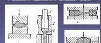
Press diagrams: a – vertical hydraulic; b – horizontal; c – crank; g – friction; d – hydraulic screw
A crank press is used in cases where it is necessary to perform simple metal forming by pressure. The main element of such equipment, which converts the rotational movement of the drive motor shaft into reciprocating movement of the slider, is the crank mechanism. That is why a crank press is often called a stamping crank press. It is very popular both among manufacturers and private craftsmen; there are even models of a tabletop crank press. This popularity is explained not only by the high efficiency and functionality of this equipment, but also by the fact that maintenance and repair of crank presses does not cause any special problems.
Hydraulic stamping press 4-column
Hydraulic stamping presses are equipped with two working chambers in which the required pressure is created in the working fluid. The liquid under pressure enters the cylinder with another piston, through which reciprocating motion is imparted to the slide.
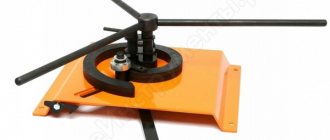
Rotary and roller forging equipment
At large manufacturing enterprises, roller-type conveyor equipment is often used to perform forging operations. The workpieces are processed using the crimping method, which is performed by rotating rollers. Rotary forging machines operate on a similar principle, the processing of parts in which is also carried out during the rotation of the working bodies.
The rotational forging method ensures waste-free processing of workpieces
Specialists who professionally engage in forging and stamping operations have to solve a number of issues in order to obtain a product of the required quality. Among such issues, in particular, are the choice of equipment, the development and production of molds, and the equipping of machines with various tools and devices.
Types of technological operations
Technological operations with metal sheets are separating and forming.
Separation stamping operations are performed on equipment equipped with special tools. As a result, a certain part is separated from the workpiece along a straight line or a given contour. The separation of part of the sheet occurs in the following processes:
- Segment _ To perform this action, the equipment is equipped with disk, vibration devices or guillotine shears.
- Trimming . This operation separates the extreme parts of the resulting product.
- Punching . Holes of various configurations are created in a metal sheet using a stamp.
- Felling . A shaped part with a closed contour is obtained from the workpiece.
Form-changing operations are intended to create a product with different parameters and dimensions without mechanical destruction. The following types of these operations are distinguished:
- Beading. The contour of the workpiece or the internal holes are exposed to the stamp to form beads of certain sizes.
- Hood. This operation is a type of volumetric stamping, in which a spatial element is obtained from a flat material.
- Crimping To narrow the ends of a hollow workpiece, a stamp with a conical-type matrix having a narrowing working area is used.
- Flexible. As a result of the operation, the curvature of the surface changes by bending the metal and deforming the workpiece.
- Molding is a change in the shape of individual sections by reducing the thickness of the part without disturbing the external contour of the product.
- Puklyovka. Connecting two plates with a stamp without using additional elements.
Types of stamping technological operations and equipment
Stamping as a method of processing metal blanks can be:
- hot;
- cold.
The first implies that the metal is processed in a heated state. The great advantage of hot stamping is that when it is performed, the characteristics of the workpiece being processed are improved (in particular, the metal structure becomes denser and more uniform). Meanwhile, a layer of scale is not created on the surface of metal workpieces processed using cold stamping technology, and the dimensions of the finished products are more accurate and their surface is smoother.
Hot stamping often replaces forging, providing more accurate dimensional accuracy
Depending on the type of workpiece being stamped, such a technological operation can be sheet or volumetric. Stamping of the first type is used for processing sheet metal blanks; this technology is used to produce:
- dishes;
- jewelry;
- weapon;
- medical equipment and instruments;
- parts of watches, household, climate control and electrical equipment;
- parts for completing automotive equipment;
- parts of machine tools and other engineering products.
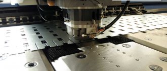
Stamping sheet metal on a coordinate turret press
Finished metal products obtained using sheet stamping technology do not require further refinement. The formation of their geometric parameters when performing volumetric stamping occurs in special forms in which hot or cold metal is subjected to extrusion.
The press machine is usually used for:
- production of metal blanks by forging;
- pressing and pressing out of shafts, bearings and gears;
- performing sheet and volume stamping.
According to the principle of operation, pressing machines can be of the mechanical or hydraulic type and perform metal processing using static or impact methods.
The single-crank mechanical press K2130 is a double-column type equipment
Mechanical pressing equipment can be designed according to its design:
- eccentric;
- crank.
Crank machines are used for both cold and hot metal stamping. This stamping equipment is also used to perform such technological operations as drawing, cutting and cutting. The hydraulic press is used for stamping and forging technological operations with bulk metal blanks.
Metal cold processing stamping shop
According to their functionality, pressing machines are divided into the following types:
- universal;
- special;
- specialized.
A universal pressing machine has the widest functionality; such equipment can be used to perform almost any forging operation. Specialized dies or presses are used to implement one technological process. Special presses that are used for stamping products of one type have minimal functionality, while their operation is based on one technology.
Radial forging equipment for hot metal processing
A radial forging machine is used to produce shafts of various diameters with high productivity. With such a unit it is possible to set up production of up to 300 thousand finished products per year, which is quite enough to supply a large manufacturing enterprise with them.
The limited use of such a machine for metal stamping is explained not only by its high cost, but also by the fact that setting up its operating modes is a rather complex process, so it is advisable to perform it only if you plan to produce products of a certain diameter in large quantities.
Radial forging machine (RFM) ensures high stamping accuracy, producing parts with minimal allowances
The sequence of actions during which radial forging is performed is as follows.
- The part is fed into an induction device to bring it to the required heating temperature.
- After the metal acquires the required degree of plasticity, the part is sent along a roller container (rolling table) to a gripping device, with the help of which it is fed into the processing zone.
- There, the workpiece is fixed by elements of another gripping device, after which it is acted upon using special strikers.
- To ensure uniform processing on all sides, the part is constantly rotated, for which a special gripping mechanism is used.
Schemes of operation of forging machines of radial and rotary type
In order to set in motion the working mechanism of equipment for radial forging, a kinematic diagram is used, the elements of which are:
- drive motor;
- V-belt transmission;
- four vertically mounted shafts with eccentric axle boxes;
- a connecting rod with a striker and a slider attached to it.
The main automatic elements of the machine are the tracing drums, which are responsible for both the synchronous approach of the strikers and the subsequent movement of the workpiece. The rotation of the grip in which the workpiece is held is imparted by an electric motor through the worm gear elements. The braking of this mechanism, which occurs during forging, is provided by a spring clutch.
» data-lazy-type=»iframe» src=»data:image/gif;base64,R0lGODlhAQABAIAAAAAAAP///yH5BAEAAAAALAAAAAABAAEAAAIBRAA7″>
One of the types of forging equipment is a horizontal forging machine, in which the workpiece is also located parallel to the ground. Devices of this type are used primarily for forming end thickenings on rod-type workpieces. During processing, the part is located in a split matrix, the channels of which are oriented in the horizontal plane.
The processing process performed on such a machine occurs in the following sequence.
- The workpiece is placed in the stationary part of the matrix.
- The moving part of the matrix, connected to the slider, is driven by the crankshaft.
- Approaching the stationary half of the mold, the movable part of the matrix tightly covers the processed rod.
- After clamping the part with the top of the mold, the crankshaft connected to the connecting rod drives the impact punches.
- At the end of processing, all moving parts of the machine return to their original position, and the moving and stationary parts of the mold are opened.
» data-lazy-type=»iframe» src=»data:image/gif;base64,R0lGODlhAQABAIAAAAAAAP///yH5BAEAAAAALAAAAAABAAEAAAIBRAA7″>
Air driven forging hammer
A pneumatic press is an efficient, but at the same time affordable forging equipment, which is also distinguished by its compact dimensions. This machine operates using the energy of compressed air, which is supplied to the mechanisms by a built-in compressor. The operation of the compressor, the pistons of which, moving in its main cylinder, create an air flow with the required pressure, is ensured by a drive electric motor.
Since the impact mechanism of a pneumatic forging machine is operated by a crank, its design resembles that of a crank press. Before starting such equipment, the compressor and working pistons in the master cylinder are in their highest and lowest positions. When the machine is put into operation, the pistons begin to move towards each other, compressing the air between them, the pressure of which is transmitted to the crank, directly connected to the striker. For one blow of the working part of the hammer of a pneumatic machine there is one revolution of the crank mechanism. Accordingly, in order for the hammer to act on the workpiece at a higher frequency, it is necessary to ensure more intensive operation of the compressor. Even despite its small dimensions, a pneumatic press can provide a hammer impact weight of up to 1 ton.
Pneumatic forging hammer MA-4129 is designed for hot stamping in open dies
A steam-air hammer operates on a principle similar to a pneumatic press, in which the impact energy is provided by hot steam supplied directly from the boiler or through a special compressor. The mass of impacts that such equipment allows to achieve can reach up to 8 tons, and the speed of their application is 50 m/sec. Depending on the model, it can work in automatic mode, when blows are applied to the part continuously, or in manual mode, when the corresponding button or pedal must be pressed to activate the striker.
Mechanical hammers can be used for:
- free forging or forging operations in which a mold is used to form the finished product;
- stamping operations with sheet metal parts - cutting along a straight or curved line, cutting along various contours, punching holes (punching press), etc.;
- punches - making products using a special template.