Power supplies for radio and electrical equipment almost always use rectifiers designed to convert alternating current to direct current. This is due to the fact that almost all electronic circuits and many other devices must be powered from DC sources. A rectifier can be any element with a nonlinear current-voltage characteristic, in other words, passing current differently in opposite directions. In modern devices, planar semiconductor diodes are usually used as such elements.
Planar semiconductor diodes
Along with good conductors and insulators, there are many substances that occupy an intermediate position in conductivity between these two classes. Such substances are called semiconductors. The resistance of a pure semiconductor decreases with increasing temperature, unlike metals, whose resistance increases under these conditions.
By adding a small amount of impurity to a pure semiconductor, its conductivity can be significantly changed. There are two classes of such impurities:
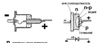
Figure 1. Planar diode: a. diode device, b. designation of a diode in electrical circuits, c. appearance of planar diodes of various powers.
The layer at the interface of p- and n-type semiconductors (pn junction) has one-way conductivity? conducts current well in one (forward) direction and very poorly in the opposite (reverse) direction. The structure of a planar diode is shown in Figure 1a. The basis ? a semiconductor plate (germanium) with a small amount of donor impurity (n-type), on which a piece of indium, which is an acceptor impurity, is placed.
Once heated, indium diffuses into the adjacent regions of the semiconductor, converting them into a p-type semiconductor. A pn junction occurs at the boundary of regions with two types of conductivity. The terminal connected to the p-type semiconductor is called the anode of the resulting diode, the opposite? its cathode. An image of a semiconductor diode on circuit diagrams is shown in Fig. 1b, appearance of planar diodes of various powers? in Fig. 1st century
History of invention
In 1873, the English scientist Frederick Guthrie developed the operating principle of directly heated vacuum tube diodes. A year later, in Germany, physicist Karl Ferdinand Braun suggested similar properties in solid-state materials and invented a point rectifier.
In early 1904, John Fleming created the first complete tube diode. He used copper oxide as the material for its manufacture. Diodes have begun to be widely used in radio frequency detectors. The study of semiconductors led to the invention of the crystal detector in 1906 by Greenleaf Witter Pickard.
In the mid-30s of the 20th century, the main research of physicists was aimed at studying the phenomena occurring at the metal-semiconductor contact boundary. Their result was the production of a silicon ingot with two types of conductivity. While studying it, in 1939, the American scientist Russell Ohl discovered a phenomenon later called the pn transition. He found that depending on the impurities existing at the interface of two semiconductors, the reducibility changes. In the early 50s, Bell Telephone Labs engineers developed planar diodes, and five years later, germanium-based diodes with a transition of less than 3 cm appeared in the USSR.
The simplest rectifier
Figure 2. Current characteristics in various circuits.
The current flowing in a conventional lighting network is variable. Its magnitude and direction change 50 times within one second. A graph of its voltage versus time is shown in Fig. 2a. Positive half-cycles are shown in red, ? negative.
Since the current value varies from zero to the maximum (amplitude) value, the concept of the effective value of current and voltage is introduced. For example, in a lighting network the effective voltage value is 220 V? in a heating device connected to this network, the same amount of heat is generated over equal periods of time as in the same device in a 220 V DC circuit.
But in fact, the network voltage changes in 0.02 s as follows:
- the first quarter of this time (period)? increases from 0 to 311 V,
- second quarter of the period? decreases from 311 V to 0,
- third quarter of the period? decreases from 0 to 311 V,
- last quarter of the period? increases from 311 V to 0.
In this case, 311 V? voltage amplitude Uо. The amplitude and effective (U) voltages are related to each other by the formula:
When a series-connected diode (VD) and load are connected to an alternating current circuit (Fig. 2b), current flows through it only during positive half-cycles (Fig. 2c). This happens due to the one-way conductivity of the diode. Is such a rectifier called half-wave? During one half of the period there is current in the circuit, during the second? absent.
The current flowing through the load in such a rectifier is not constant, but pulsating. You can turn it almost constant by connecting a filter capacitor Cf of a sufficiently large capacity in parallel with the load. During the first quarter of the period, the capacitor is charged to the amplitude value, and in the intervals between pulsations it is discharged to the load. The tension becomes almost constant. The greater the capacitor capacity, the stronger the smoothing effect.
Direct and alternating current
From the physics course, everyone knows that electric current involves the flow of electric charge from one conductor to another. Unlike direct current, which actually flows in one direction (from negative to positive), alternating current flows first in one direction and then in the other. If you connect an oscilloscope to a power outlet, you can get a schematic representation of such current movement.
The figure shows an alternating current oscillogram, where the x-axis shows time and the y-axis shows voltage. The graph clearly shows that the voltage smoothly increases to a value of 220 V, then decreases to zero and increases to the same value, but with the opposite sign. In other words, the voltage in the outlet constantly changes sign at a rate of 50 times per second.
For comparison, you can connect the oscilloscope probes to a DC source. Battery terminals can be used as it. In this case, the picture will be somewhat different.
The DC waveform shown in the image clearly demonstrates how the terminal voltage remains constant throughout the entire time. When the circuit is closed, the current will flow in one direction.
Diode bridge circuit
More advanced is the full-wave rectification circuit, when both positive and negative half-cycles are used. There are several varieties of such schemes, but the most commonly used is pavement. The diode bridge circuit is shown in Fig. 3c. The red line on it shows how current flows through the load during positive times, and the blue line? negative half-cycles.
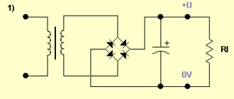
Figure 4. 12 volt rectifier circuit using a diode bridge.
In both the first and second half of the period, the current through the load flows in the same direction (Fig. 3b). The amount of pulsation within one second is not 50, as with half-wave rectification, but 100. Accordingly, with the same filter capacitor capacity, the smoothing effect will be more pronounced.
As you can see, to build a diode bridge you need 4 diodes? VD1-VD4. Previously, diode bridges on circuit diagrams were depicted exactly as in Fig. 3c. The image shown in Fig. 1 is now generally accepted. 3g. Although there is only one picture of a diode, it should not be forgotten that the bridge consists of four diodes.
The bridge circuit is most often assembled from individual diodes, but sometimes monolithic diode assemblies are also used. They are easier to mount on the board, but if one arm of the bridge fails, the entire assembly is replaced. The diodes from which the bridge is mounted are selected based on the amount of current flowing through them and the amount of permissible reverse voltage. This data can be obtained from diode instructions or reference books.
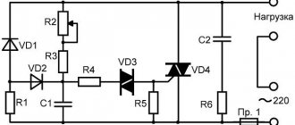
The complete circuit of a 12 volt rectifier using a diode bridge is shown in Fig. 4. T1? step-down transformer, the secondary winding of which provides a voltage of 10-12 V. Fuse FU1? This is a useful detail from a safety point of view and should not be neglected. The brand of diodes VD1-VD4, as already mentioned, is determined by the amount of current that will be consumed from the rectifier. Capacitor C1? electrolytic, with a capacity of 1000.0 μF or higher for a voltage of at least 16 V.
Output voltage? fixed, its value depends on the load. The higher the current, the lower the voltage. To obtain a regulated and stable output voltage, a more complex circuit is required. Obtain the regulated voltage from the circuit shown in Fig. 4 can be done in two ways:
It is hoped that the descriptions and diagrams given above will provide practical assistance in assembling a simple rectifier for practical needs.
There is an inconsistency in electrical engineering. On the one hand, it is more convenient to transmit energy over long distances if it is in the form of alternating voltage. On the other hand, direct current is required to power smartphones, LEDs in light bulbs, circuit boards in TVs and similar household appliances. This problem is successfully solved by a family of radio components such as rectifier diodes.
A little theory about batteries
Any battery is a storage device for electrical energy. When voltage is applied to it, energy is stored due to chemical changes inside the battery. When a consumer is connected, the opposite process occurs: a reverse chemical change creates voltage at the terminals of the device, and current flows through the load. Thus, in order to get voltage from the battery, you first need to “put it down,” that is, charge the battery.
Almost any car has its own generator, which, when the engine is running, provides power to the on-board equipment and charges the battery, replenishing the energy spent on starting the engine. But in some cases (frequent or difficult engine starts, short trips, etc.) the battery energy does not have time to be restored, and the battery is gradually discharged. There is only one way out of this situation - charging with an external charger.
How to find out the battery status
To decide whether charging is necessary, you need to determine the state of the battery. The simplest option - “turns/does not turn” - is at the same time unsuccessful. If the battery “doesn’t turn”, for example, in the garage in the morning, then you won’t go anywhere at all. The “does not turn” condition is critical, and the consequences for the battery can be dire.
The optimal and reliable method for checking the condition of a battery is to measure the voltage on it with a conventional tester. At an air temperature of about 20 degrees, the dependence of the degree of charge on the voltage at the terminals of a battery disconnected from the load (!) is as follows:
- 12.6…12.7 V - fully charged;
- 12.3…12.4 V - 75%;
- 12.0…12.1 V - 50%;
- 11.8…11.9 V - 25%;
- 11.6…11.7 V - discharged;
- below 11.6 V - deep discharge.
It should be noted that the voltage of 10.6 volts is critical. If it drops below, the “car battery” (especially a maintenance-free one) will fail.
Correct charging
There are two methods of charging a car battery - constant voltage and constant current. Each has its own characteristics and disadvantages:
- Constant voltage charging - suitable for restoring the charge of not completely discharged batteries, the voltage at the terminals of which is not lower than 12.3 V. The process is as follows: a direct current source with a voltage of 14.2–14.7 V is connected to the battery terminals. The end of the process is monitored by the current consumption: when it drops to zero, charging is considered complete. The disadvantage of this method is that the initial charging current may be high; The more the battery is discharged, the higher the current. The advantages of the method are obvious - you do not need to constantly adjust the charging current, and the battery is not in danger of being overcharged if you forget about it.
- DC charging is the most common and reliable method. In this mode, the charger produces a constant current equal to 1/10 of the battery capacity. The end of the charging process is determined by the voltage on the battery - when it reaches 14.7 V, the battery stops charging. The disadvantage of this method is that the battery can be damaged if you do not remove it from charging in time.
What are diodes
A diode is a semiconductor element based on a silicon crystal. Previously, these parts were also made of germanium, but over time this material was forced out due to its shortcomings. The electrical diode functions as a valve, i.e. it allows current to flow in one direction and blocks it in the other. Such capabilities are built into this part at the level of the atomic structure of its semiconductor crystals.
Read also: Fursuit. Making a head from foam rubber
One diode cannot obtain a full constant voltage from an alternating voltage. Therefore, in practice, more complex combinations of these elements are used. An assembly of 4 or 6 parts, combined according to a special circuit, forms a diode bridge. He is already quite capable of coping with full current rectification.
Interesting. Diodes have parasitic sensitivity to temperature and light. Transparent rectifiers in a glass case can be used as light sensors. Germanium diodes (approx. D9B) are suitable as a temperature-sensitive element. Actually, due to the strong dependence of the properties of these elements on temperature, they stopped producing them.
How to solder and connect
It is not difficult to study and know the circuits; the main difficulties arise when a beginner decides to solder a diode bridge with his own hands. To solder a rectifier from 4 Soviet copies of the KD202 type, use the illustration below.
To assemble a diode bridge from modern discrete diodes such as low-power 1n4007 (and others - they all look similar and differ only in size), take a close look at the following illustration.
But if you do not assemble it from separate parts, but use a ready-made bridge, then see below how to properly connect it to the circuit.
Also, beginners will be interested in watching a video on how to make a simple 12V power supply:
Tags: , ampere, anode, battery, sconce, view, choice, generator, house, , capacity, charging, measurement, pulse, like, computer, capacitor, design, circuit, , magnet, marking, installation, power, voltage, oscilloscope, variable, connection, polarity, constant, rule, principle, wire, start, , work, size, calculation, resistor, rheostat, socket, row, garden, homemade, light, LED, network, resistance, stabilizer, circuit, ten , type, current, transistor, transformer, three-phase, , installation, phase, filter, electricity, electronic, power supply, effect
Single-phase and three-phase diode bridge
There are two main types of straightening assemblies:
- Single-phase bridge. Most often used in household electrical appliances. Has 4 outputs. Two of them are supplied with alternating voltage, i.e. phase (L) and zero (N). The permanent one is removed from the remaining two, i.e. plus (+) and minus (-).
- Three-phase bridge. It is found in powerful industrial installations and equipment powered by a 380 volt network. Three phases are supplied to its input (L1, L2, L3). The constant voltage is also removed from the output. Such bridges are distinguished by their large size and impressive currents that they are capable of passing through themselves.
Practical use
In practice, the diode bridge has a fairly wide range of applications - this includes digital technology, power supplies in personal computers, laptops, various devices, car generators powered by low DC voltage. In addition, they can be found in sound reproduction systems, measuring equipment, television and radio broadcasting, and they are installed in a number of different devices throughout the house. To better understand the role of the diode bridge in these devices, we will look at several specific circuits in which it is used.
Examples of diode bridge circuits and their descriptions
One of the simplest circuits using a diode bridge is a charger used for equipment powered by low voltage. Let's look at one of these options using the following example:
Rice. 5. Charger circuit
As you can see in the figure, from the step-down transformer T1 the voltage from alternating 220V is converted to alternating at a level of 7 - 9V. After this, the reduced voltage is supplied to the diode bridge VD, from which it is rectified through the smoothing capacitor C1 to the KR microcircuit. The rectified voltage from the microcircuit is stabilized and supplied to the connector terminals.
Rice. 6. Flashlight diagram
The figure above shows an example of a flashlight circuit; this model is connected to a 220V household network through a socket, which is represented by connecting connectors X1 and X2. Next, the voltage is supplied to the VD bridge, and from it to the DA1 chip, which, if there is input power, signals this through the HL1 LED. After this, the power supply is supplied to the GB battery, which is charged and then used as the main power source for the flashlight lamp.
Example of a welding unit diagram
Here is an example of a welding unit circuit in which a diode bridge is installed immediately after a step-down transformer to rectify the electric current. Due to the complexity of the circuit, further consideration of the operation of the device is impractical. It is worth noting that there are other devices with an even more complex operating principle - switching power supplies, PWM modulators, converters, etc.
Operating principle of a diode bridge
You can understand how a bridge performs its task by understanding how a separate diode behaves. Initially there are only two wires with alternating voltage (L and N). It has the shape of a sinusoid (Fig. a). If you add one diode to the circuit, then it will transmit only the positive half-wave (Fig. b), if this component is deployed, then the negative component (Fig. c). This voltage will no longer be variable. However, it is not suitable for powering serious electrical appliances. There are moments in it when there is no current at all. The use of four diodes will allow you to obtain a constant voltage without any interruptions (Fig. d). Three-phase bridges are straightened using the same method. However, they do this with three sine waves at the same time.
Rectifier
The voltage obtained after the diode bridge has the shape of a sinusoid, in which the negative component is reflected relative to the time axis. In simple terms, it is shaped like hills and is called pulsating. This voltage is positive. Does not contain moments when current does not flow. But it is still unstable. For example, at point “a” it is early 0 volts, and at “b” it has a maximum value. This rectifier cannot be considered complete.
To solve this problem, a smoothing electrolytic capacitor is required. On the board it is usually located in the same place as the diode assembly. The capacitance accumulates energy at those moments when it has peak values (point b), and releases it at moments of dips (a). The output is a straight line - full-fledged direct current, suitable for powering subsequent electronic components, processors, microcircuits, etc.
Calculation of the number of turns
The number of layers for each winding is determined from the core area using the formula K = 50: Sc = 50/45 = 1.11 turns per volt.
Attention! In this formula, as well as in the first, the coefficient of 50 is adopted for transformers with cores of types P and Sh., for ring cores it will be equal to 35 for, ShL and ShP - 40.
Now we determine the maximum current on the primary winding using the formula: Imax = P: U = 6750: 220 = 30.71 A. Based on these data, you can find out the number of layers for winding. The calculation is carried out using the formula Wx = Ux * K. For the secondary, it will be W2 = U2 x K = 60 x 1.11 = 67 turns.
We will find out the number of layers of the primary winding later because To do this, you need to apply a different formula. To adjust the output power, several outputs are made from the primary winding. The number of turns for the primary winding is found by the formula: W1st = (U1 x W2): Ust, vit.
Where:
- Ust – voltage on the secondary winding.
- U1 – voltage of the primary winding;
- W2 – number of turns of the secondary winding;
- W1st – the number of primary windings of a certain stage.
But first it is necessary to calculate the voltage of each stage Ust. To do this, we use the formula U=P: I, B.
Using the formula U = P: I, V. for the original design transformer P = 6750 W, we calculate the data for four stages with a power of 95 A, 110 A, 135 A and 165 A. Substituting the data into the formula, we obtain U1st1 = 6750:95 = 71 V, U1st2=61 V, U1st3=50 V, U1st4=41 V.
Next, we use the obtained data to calculate the winding. According to the formula W1st = (U1 x W2): Ust, vit. we get the number of turns for each stage (rounded up) W1st1 = (220x67): 71 = 208 turns, W1st2 = 242 W1st3 = 295 turns, W1st4 = 359 turns.
By adding a value of 6% to the larger number of turns, we obtain the required calculated total number of turns of the primary winding W1 = 359 + 18 = 377.
Finally, let's calculate the cross-section of the wire on the primary and secondary windings. To do this, divide the maximum current for each winding by the current density. As a result of the calculation: Ssecond = 165: 3 = 55 mm2, Sfirst = 11 mm2.
As a result, the calculation of a welding transformer powered from a single-phase network U1 = 220V, with a power of 6.75 kW. we get:
Iron: U-shaped stamped sheets of transformer steel 0.5 mm thick Type of windings - circular wound on a frame; Number of turns W1 = 377 V., W2 = 67 V., Number of adjustable steps - 4. at Ireg - 95 A, 110 A, 135 A and 165 A. Wire cross-section Ssecond = 55 mm2, Sfirst = 11 mm2
Disadvantages of a full bridge
A full-fledged full-wave bridge has disadvantages:
- The current is forced to flow not through one diode, but through two at once, connected in series. Therefore, the voltage drop across the rectifier element doubles. For low-power bridges on silicon diodes it can reach 2 volts. In powerful rectifiers - about 10 V. Hence, significant power losses on the rectifying element and its increased heating.
- If one or four diodes fail, the bridge continues to operate. This defect may not be noticeable without special measurements. However, it creates the risk of more serious damage to the device, which is powered through a faulty bridge.
Calculation of the cross-section of the wires of the primary winding of the transformer
Diagram of a welding transformer.
The theory of transformers is complex in that it is based on the laws of electromagnetic induction and other phenomena of magnetism. However, without using complex mathematical apparatus, it is possible to explain how a transformer works and whether it can be assembled independently.
The transformer can be manually wound on a metal core assembled from transformer steel plates. It is easier to wind on a rod or armored core than on a toroidal one.
You should immediately note that the image clearly shows the difference in the thickness of the wires: the thin wire is located directly on the core, and a larger number of turns is clearly visible in it. This is the primary winding.
The thicker wire with fewer turns is the secondary winding.
Without taking into account the power losses inside the transformer, let's calculate what the current I1 should be in its primary winding.
The ideal network voltage is U=220 V. Knowing the power consumption, for example, P=5 kW, we have:
I1 = P:U= 5000_220=22.7 A.
Based on the current in the primary winding of the transformer, we determine the diameter of the wire. The current density for a household welding transformer should be no more than 5 A/mm2 of wire cross-section. Therefore, for the primary winding you will need a wire with a cross section of S1 = 22.7:5 = 4.54 mm2.
Using the cross-section of the wire, we determine the square, its diameter d without taking into account the insulation:
d2=4S/π=4×4.54/3.14=5.78.
Taking the square root, we get d=2.4 mm. These calculations were performed for copper wire cores. When winding wires with an aluminum core, the obtained result must be increased by 1.6-1.7 times.
For the primary winding, copper wire is used, the insulation of which must withstand high temperatures well. This is fiberglass or cotton insulation. Rubber and rubber-fabric insulation is suitable. Wires with PVC insulation should not be used.
Design
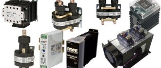
The circuit of any rectifier bridge includes diodes. They can be separately soldered onto a printed circuit board or located in the same housing. Regarding the size, rectifiers are miniature, for example, imported MB6S or Soviet KTs405A. The latter are popularly called “ka-tseshki” or “chocolates”.
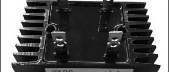
There are samples with impressive dimensions. For example, a three-phase rectifier bridge made in China. The device is designed for currents of hundreds of amperes, therefore it has screw fastening for power wires and a flat metal heat-conducting surface with holes for fixing on the cooling radiator.
Features of rectifiers
The rectifier for the welding machine is made according to a bridge circuit. When manufacturing and using B200 diodes, it is necessary to take into account that their housing is energized.
Therefore, when the rectifier is installed on a radiator, it must be isolated from the rest of the circuit elements, from the device body and from neighboring diodes too. And this creates certain inconveniences for the welder.
You have to use a larger body. To reduce the dimensions of the device, a VL200 rectifier device is used, which has a different polarity. This allows semiconductors to be combined into two paired heatsinks.
In recent years, quite powerful diode bridges in one housing have begun to be produced. In size, such a design of diodes approximately corresponds to a matchbox, has a platform for landing a radiator, and a maximum forward current of 30-50 A. The diode assembly has a significantly lower cost compared to B200 diodes.
If the operation of the device requires a more powerful bridge, then this problem can be easily solved by using parallel connection of bridge assemblies. However, their reliability in this case will be lower than that of single powerful diodes.
Rectifier markings
There are no generally accepted rules according to which manufacturers label their diode bridges. Everyone has the right to name their product as they see fit, i.e. according to its own nomenclature.
However, most of these parts have similar features that help visually determine the purpose of their pins. In the photo of a three-phase bridge (see above), the alternating current symbol is highlighted separately - a wavy line. It indicates that a sinusoidal input voltage is connected to this pin. Also on some bridge models, the input terminals are marked with the letters AC (Alternative Current), indicating alternating current. In this case, the output contacts from which direct current is removed are indicated by the symbols DC (Direct Current) or the traditional “+” and “-”. Additionally, on some rectifiers, one of the corners is “filed” on the plus side. An extended pin can also indicate “+”. This type of marking is common to many electronic components and is called a key.
Manufacturing of welding machine
Today it is almost impossible and quite difficult to weld metal or process it in the proper way without using welding equipment. After you make a welding machine with your own hands, you will be able to perform any work with metal products.
Transformer circuit with a separate choke.
To produce a high-quality unit, you must have knowledge and skills that will help you understand the circuit of a DC or AC welding machine, which are two options for assembling equipment.
For home use, it is best to learn how to make mini welding.
It is more convenient to call a specialist or purchase a ready-made unit, but sometimes this can be too expensive, since it is quite difficult to determine the choice of model based on various parameters, such as the weight of the welding machine, and the number of volts per welding machine.
There are several types of welding machines: operating on alternating current, direct current, having three phases or inverter. To choose one of the options and start assembling, you need to consider each circuit of the first 2 types
During the preparatory process, you need to pay attention to the voltage stabilizer
AC
To make homemade welding machines, you need to select a voltage indicator, the best is 60 volts, the current is best adjusted from 120 to 160 amperes.
You can independently determine the cross-sectional value of the required wire for the manufacture of the primary winding of the transformer, which must be connected to a 220-volt network.
The cross-section according to the area parameters should not be more than 7 mm2, since it is worth noting the possible voltage drop and possible additional load.
Based on calculations, the optimal size of the diameter of the copper core for the primary winding, which reduces the action of the mechanism, is 3 millimeters. When choosing aluminum for the wire, the cross-section is multiplied by 1.6.
If the necessary wire is not available, it is possible to replace it with a slightly thinner wire, winding it in pairs. However, it must be remembered that the thickness of the winding will increase, which is why the dimensions of the welding equipment will be larger. For the secondary winding, a thick wire with a large number of copper cores is used.
DC
Electrical circuit of a DC welder.
Some welding machines operate using direct current. Thanks to this unit, you can weld cast iron products and stainless steel structures.
It may take no more than half an hour to create a DC welding machine with your own hands. In order to convert a homemade product with alternating current, it is necessary that the secondary winding be connected to a rectifier, which is assembled on a diode.
In turn, the diode must withstand a current of 200 amperes and have good cooling. To equalize the current value, you can use capacitors that have certain characteristics and voltage characteristics. After this, the unit is assembled sequentially according to the scheme.
Chokes are used to regulate current, and contacts are used to attach a holder. Additional parts are used to transmit current from an external carrier to the welding site.
DIY diode bridge
To assemble the rectifier yourself, you will need 4 diodes of the same type. At the same time, they must be suitable in terms of reverse voltage, maximum current and operating frequency. Connections must be made in accordance with the diagram below. A positive voltage is removed between the two cathodes and a negative voltage between the anodes. An alternating voltage source is connected to the points at which opposite terminals of the diodes are connected. The entire circuit can be soldered by surface mounting in a couple of minutes, or you can work hard and make it in the form of a small printed circuit board.
Additional Information. The reverse voltages of diodes connected in a series circuit are added to each other.
Requirements for structural assembly
The circuit for a simple rectifier is not particularly complicated; you will need conductors that pass the electrical flow and are directed in the right direction.
Welding rectifier circuit
Electrical parts should be prepared from the following configuration:
- diodes - they allow the circuit to operate without control units
- thyristors that supply signals to elements for good electrical passage
- flows, when they decrease, the valves close
- transistors that control all processes with voltage
- resistors that allow you to regulate the current
In order for electrical elements to serve longer in operation, they are selected with high parameters, while ensuring that the actual current in the circuit is less than the specified nominal value.
The welding rectifier is assembled using the following items:
- transformer
- diode
- radiator
- throttle
- electrode
- capacitor
- ceramic core
- nickel wire
The assembled semiconductor circuit in the form of a diode rectifier is installed with a radiator that provides heat exchange and cooling. A choke is provided for the falling characteristic of the electric current, an increased resistance or a rheostat is used to regulate the required parameters. The poles, positive and negative, are connected to the electrode and the object.
The function of the electrolytic capacitor in the circuit serves to implement smoothing filtering and reduce ripple.
Many specialists independently cope with winding rheostats on ceramic cores. Use nichrome or nickel wire. Their diametric selection depends on the magnitude of the welding current flows.
Rheostatic resistance is calculated based on the wire parameters:
- resistivity
- section
- length
Adjustment of the welding current depends on the number of turns.
Selecting a build type
For each task there is its own optimal version of the rectifier diode assembly. All of them can be divided into 3 types:
- Rectifier with one diode. It is used in the simplest and cheapest circuits where there is no c.l. requirements for the quality of the output voltage, as, for example, in night lights.
- Dual diode. These parts look similar to transistors, because they are produced in the same packages. They also have 3 pins. Essentially, these are two diodes placed in one housing. One of the conclusions is average. It can be the common cathode or the anode of the internal diodes.
- Full diode bridge. 4 parts in one case. Suitable for devices with high currents. It is mainly used on the inputs and outputs of various power supplies and chargers.
Additional Information. Rectifiers are also used in cars. They are needed to convert the alternating voltage coming from the generator to direct voltage. This, in turn, is necessary to charge the battery. A conventional gas generator produces alternating current.
Read also: Affordable and simple: how to make a beautiful envelope from A4 sheet
Features of voltage types
A natural question arises about why alternating current is used in sockets, if the vast majority of electronic equipment is powered by direct current. The fact is that to power the nodes of this or that equipment, voltages of different magnitudes are required. A computer processor, for example, is powered by 3 V, and a mobile phone requires as much as 5 V to charge. A music center amplifier already needs about 25 V.
DC voltage is quite difficult to transform from one value to another, but alternating voltage is easy. For example, transformers are used for this. Some important power components, such as motors, still require AC power. Therefore, industrial generators that power household sockets produce it to a generally accepted value (for example, 220 V), and each device already receives from it what it needs on site.
Checking elements
In most cases, it is not necessary to unsolder the bridge from the board for testing. It should be tested in the same way as a 4 pn junction with a diode bridge connection. This measurement is so common that its capability is implemented in any multimeter. The test device must be switched to diode continuity mode.
The forward voltage drop across a working rectifier diode is 500-700 mV. Otherwise, the device will display “1”. A burnt part most often shows “0” in both directions, i.e. short circuit. Less often, a complete breakage of the element occurs (also in both directions). All measurements should be repeated for each diode included in the bridge. Total 8 measurements, i.e. 4 in forward direction and 4 in reverse. If a Schottky diode is tested, then this parameter is 200-400 mV.
Specifications
When choosing a specific diode bridge to replace in a rectifier block or for any other circuit, it is important to have a good understanding of the basic technical parameters.
Among these characteristics, the most significant for a diode bridge are:
- The maximum amplitude voltage of reverse polarity is a threshold value beyond which an irreversible process will already occur and the semiconductor will fail. Designated as UAobr in domestic models or Vrpm for foreign ones.
- Average reverse voltage - represents the nominal value of an electrical quantity that can be applied during operation. It is designated Uobr in domestic samples or Vr(rms) for foreign diode bridges.
- Average rectified current - indicates the effective value of the electric current at the output of the diode bridge. On devices it is indicated as Ipr or Io for models of domestic or foreign production, respectively.
- The peak-to-peak rectified current is the maximum current at the output of the rectifier, determined by the half-wave peak on the curve, denoted as Ifsm for the pulsating current at the positive and negative terminals.
- Voltage drop in direct polarity - determines the voltage loss from the diode bridge’s own resistance. On the device it is designated as Vfm.
If you want to choose a replacement model, let’s say in a 220 V network, then the main parameter for the diode bridge is reverse current and voltage. The performance characteristics must significantly exceed the network rating, for example, at a voltage of 220 V - the diode bridge must withstand about 400 V. In terms of current, a smaller reserve is suitable, but it should also be provided for.
Using the Schottky barrier
The use of a Schottky diode is justified in two cases. Firstly, when you need to rectify high-frequency current. The Schottky barrier is ideal for such a task, because it has a low junction capacitance and, accordingly, is fast-acting. Secondly, when it is necessary to rectify a large current of tens or hundreds of amperes. In this case, the part performs well due to the low voltage drop and low heat generation.
Diode bridges in the world of electronics play the role of a matching element. With their help, you can connect devices that require direct current to a network of alternating voltage convenient for transmission. There are a lot of such devices in everyday life; they are extremely important for a person’s comfortable life.
The main element used to create a rectifier unit is a diode. Its operation is based on the electron-hole transition (pn).
The generally accepted definition says: a pn junction is a region of space located at the boundary of the junction of two semiconductors of different types. In this space, an n-type to p-type transition is formed. The value of conductivity depends on the atomic structure of the material, namely on how tightly the atoms hold electrons. Atoms in semiconductors are arranged in a lattice, and electrons are bound to them by electrochemical forces. This material itself is a dielectric. It either conducts current poorly or does not conduct it at all. But if atoms of certain elements are added to the lattice (doping), the physical properties of such a material change radically.
Mixed atoms begin to form, depending on their nature, free electrons or holes. The resulting excess electrons form a negative charge, and the holes form a positive charge.
An excess charge of one sign causes carriers to repel each other, while an area with an opposite charge tends to attract them towards itself. An electron, moving, occupies a free space, a hole. At the same time, a hole also forms in its old place. As a result, two flows of charge movement are created: one main and the other reverse. A material with a negative charge uses electrons as majority carriers and is called an n-type semiconductor, while a material with a positive charge using holes is called a p-type semiconductor. In both types of semiconductors, minority charges generate a current opposite to the movement of the main charges.
In radio electronics, germanium and silicon are used from materials to create pn junctions. When crystals of these substances are doped, a semiconductor with different conductivity is formed. For example, the introduction of boron leads to the appearance of free holes and the formation of p-type conductivity. Adding phosphorus, on the other hand, will create electrons and the semiconductor will become n-type.
Transformers (with or without rectifier)
The heart of a transformer is the core. It is assembled from transformer steel plates, which are quite problematic to make by hand. By hook or by crook, the source material is extracted at factories, construction teams, and scrap metal collection points. The resulting structure (usually in the form of a rectangle) must have a cross-section of no less than 55 cm². This is a rather heavy structure, especially after laying the windings.
During assembly, it is imperative to provide an adjusting screw, with which you can move the secondary winding relative to the stationary primary.
In order not to go into the complexity of calculating the cross-section of wires, we will take typical parameters:
- secondary current 100–150 A;
- open circuit voltage 60–65 volts;
- operating voltage when welding 18–25 volts;
- current on the primary winding is up to 25 A.
Based on this, the cross-section of the primary wire should be at least 5 mm²; if you do it with a margin, you can take a wire of 6–7 mm². The insulation must be heat-resistant and made from a material that does not support combustion.
The secondary winding is made of wire (or better yet, a copper busbar) with a cross-section of 30 mm². The insulation is rag. Don't let the thickness scare you, the number of turns on the secondary is small.
The number of turns of the primary winding is determined by a coefficient of 0.9–1 turns per volt (for our parameters).
The formula looks like this:
W(number of turns) = U(voltage) / coefficient.
That is, with a network voltage of 200–210 volts, it will be about 230–250 turns.
Accordingly, if the secondary voltage is 60–65 volts, the number of its turns will be 67–70.
From a technical point of view, the transformer is ready. For ease of use, it is recommended to make a small margin on the secondary winding, with several branches (at 65, 70, 80 turns). This will allow you to work confidently in places with low network voltage.
Hiding the unit in the housing or leaving it open is a matter of safety of use. A typical DIY welding transformer looks like this:
The optimal material for the case is 10–15 mm textolite.
Adding a rectifier
A homemade powerful welding transformer from a circuit design point of view is a regular power supply. Accordingly, the rectifier is designed as simply as in a network charger for a mobile phone. Only the element base will look several orders of magnitude more massive.
As a rule, a pair of capacitors are added to a simple diode bridge circuit to dampen rectified current pulses.
You can assemble a rectifier without them, but the smoother the current, the better the quality of the weld. To assemble the bridge itself, powerful diodes of the D161–250(320) type are used. Since a lot of heat is generated on the elements when loaded, it must be dissipated using radiators. The diodes are attached to them using a bolt connection and thermal paste.
Of course, the radiator fins must either be blown by a fan or protrude above the case. Otherwise, instead of cooling, they will heat the transformer.
Mini welding transformer
If you do not need to weld rails or channels from 4–5 mm steel, you can assemble a compact welder for soldering steel wire (making frames for homemade products) or welding thin sheet metal. To do this, you can take a ready-made transformer from a powerful household appliance (the ideal option is a microwave) and rewind the secondary winding. Wire cross-section 15–20 mm², power consumption no more than 2–3 kW.
The calculation of the circuit is carried out in the same way as for more powerful units. When assembling the rectifier, you can use less powerful diodes.
Micro welder
If the scope of application is limited to soldering copper wires (for example, when installing distribution boxes), you can limit yourself to a design the size of a pair of matchboxes.
Performed on transistor KT835 (837). The transformer is manufactured independently. In fact, it is a high-frequency boost converter.
We wind the transformer on a ferrite rod. Two primary windings: collector (20 turns 1 mm), base (5 turns 0.5 mm). Secondary (boost) winding - 500 turns of 0.15 wire.
We assemble the circuit, solder the resistor circuit according to the circuit (so that the transformer does not overheat at idle), the device is ready. Power supply from 12 to 24 volts, with the help of such a device you can weld wire harnesses, cut thin steel, and join metals up to 1 mm thick.
A thick sewing needle can be used as welding electrodes.
Diode operating principle
A diode is a semiconductor device that has low resistance to current in one direction and prevents it from flowing in the opposite direction. Physically, the diode consists of one pn junction. Structurally, it is an element containing two outputs. The terminal connected to the p-region is called the anode, and the terminal connected to the n-region is called the cathode.
When a diode operates, there are three states:
A forward potential is a signal when the positive pole of the power source is connected to the p-type region of the semiconductor, in other words, the polarity of the external voltage coincides with the polarity of the main carriers. With reverse potential, the negative pole is connected to the p-region and the positive pole to the n region.
There is a potential barrier in the area where the n- and p-type material joins. It is formed by a contact potential difference and is in a balanced state. The height of the barrier does not exceed tenths of a volt and prevents the movement of charge carriers deep into the material.
If direct voltage is connected to the device, then the magnitude of the potential barrier decreases and it practically does not resist the flow of current. Its value increases and depends only on the resistance of the p- and n-regions. When a reverse potential is applied, the barrier value increases, since electrons leave the n-region and holes leave the p-region. The layers become depleted and the barrier's resistance to the passage of current increases.
The main indicator of an element is the current-voltage characteristic. It shows the relationship between the potential applied to it and the current flowing through it. This characteristic is presented in the form of a graph, which indicates the forward and reverse current.
Advantages and disadvantages
In addition to the diode bridge, there are other ways to convert alternating current to direct current. Compared to half-wave rectification, full-wave rectification has a number of advantages:
- Both the negative and positive half-waves of the sine wave are converted into output voltage, so that the entire power of the transformer is used to the most optimal extent.
- Due to the higher pulsation frequency, the voltage received from the diode rectifier is much easier to smooth out using filters.
- The use of electricity under load reduces power losses due to core magnetization reversal, which occurs due to mutual induction processes in the windings of the supply transformer.
- Harmonious redistribution of the curve of electric current and voltage at the output - due to the transmission of each half-cycle by two diodes in the bridge at once, the output parameter is much more uniform.
The disadvantages of a diode bridge include a larger voltage drop compared to a half-wave circuit or a midpoint-tapped rectifier. This is due to the fact that current flows through two semiconductor elements at once and encounters ohmic resistance from each of them. Such a disadvantage can have a significant impact in low-current circuits, where fractions of an ampere can determine the value of signals, operating modes of units, etc. As a solution, diode bridges with Schottky diodes, which have a relatively lower forward voltage drop, can be used.
Another disadvantage is the difficulty of identifying a burnt-out link, since if at least one diode fails, the entire circuit will continue to work. It is possible to understand that one of the semiconductor elements has fallen out of the circuit only through measurements; it is not always the case that a device or circuit will react with a visible malfunction when it fails.
It’s also important to know: 3 nuances about operation
The homemade product differs somewhat in its method of operation from the factory version. This is explained by the fact that the purchased unit has built-in functions that help with operation. They are difficult to install on a device assembled at home, and therefore you will have to adhere to several rules during operation.
- A self-assembled charger will not turn off when the battery is fully charged. That is why it is necessary to periodically monitor the equipment and connect a multimeter to it to monitor the charge.
- You need to be very careful not to confuse “plus” and “minus”, otherwise the charger will burn out.
- The equipment must be turned off when connecting to the charger.
By following these simple rules, you will be able to properly recharge the battery and avoid unpleasant consequences.
Types of devices, their features
DIY welding rectifier
A homemade welding rectifier is needed to effectively power a household or industrial structure with small volumes of work and work cycles.
In industry, more powerful equipment is used; operations with it do not create pauses during welding.
During this period, the hot parts cool down, the speed of the procedure decreases, which does not interfere with home appliances.
These products consist of elements:
- transformer
- capacitor unit
- rectifier
When starting to create a welding device, the master needs to decide on the direction of work and its dimensions.
The following depends on the volume of production and the number of connections:
- selection of the necessary electrodes
- system parameters
- material characteristic
The assembler, having selected the necessary diagram and materials, and having assembled the device step by step, will achieve the necessary indicators in the system.
Simple rectifier circuit
Sinusoidal voltage is a periodic signal that varies over time. From a mathematical point of view, it is described by a function in which the origin corresponds to time equal to zero. The signal consists of two half-waves. The half-wave located in the upper part of the coordinates relative to zero is called a positive half-cycle, and in the lower part - negative.
When an alternating voltage is applied to the diode through a load connected to its terminals, current begins to flow. This current is due to the fact that at the moment the positive half-cycle of the input signal arrives, the diode opens. In this case, a positive potential is applied to the anode and a negative potential to the cathode. When the wave changes to a negative half-cycle, the diode is turned off, as the polarity of the signal at its terminals changes.
Thus, it turns out that the diode, as it were, cuts off the negative half-wave, without passing it to the load, and a pulsating current of only one polarity appears on it. Depending on the frequency of the applied voltage, and for industrial networks it is 50 Hz, the distance between the pulses also changes. This type of current is called rectified, and the process itself is called half-wave rectification.
Read also: How to build a brick tandoor
By rectifying the signal using a single diode, you can power a load that does not have special requirements for voltage quality. For example, a filament. But if you power up, for example, a receiver, a low-frequency hum will appear, the source of which will be the gap that occurs between the pulses. To some extent, to get rid of the disadvantages of half-wave rectification, a capacitor connected in parallel with the load is used together with a diode. This capacitor will charge when pulses arrive and discharge when there are no pulses to the load. This means that the larger the capacitance value of the capacitor, the smoother the current across the load will be.
But the highest signal quality can be achieved if two half-waves are used simultaneously for rectification. The device that allows this to be realized is called a diode bridge, or in other words, a rectifier bridge.
Installation
When using a parallel circuit for connecting diode bridges, it is necessary to take into account that they all have some variation in parameters.
Therefore, when selecting elements, it is necessary to do this with some margin of safety. If this requirement is met, a more compact diode bridge can be obtained for the welding machine than when using single diodes.
Diode assemblies allow them to be placed on one radiator, since the cases are not energized. This allows you to install them anywhere, even outside.
Depending on the required welding current, the rectifier may require 3 to 5 diode assemblies. For better heat transfer, diode bridges are installed on the radiator through heat-conducting paste.
It is recommended to connect conductors to the contacts by soldering, otherwise there may be power losses at the contact point and its strong heating.
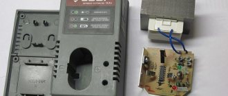
Setting the output voltage and charging current
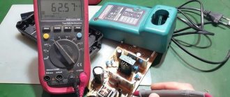
There are two trimming resistors installed on the DC-DC converter board, one allows you to set the maximum output voltage, the other allows you to set the maximum charging current.
Plug in the charger (nothing is connected to the output wires), the indicator will show the voltage at the device output and the current is zero. Use the voltage potentiometer to set the output to 5 volts. Close the output wires together, use the current potentiometer to set the short circuit current to 6 A. Then eliminate the short circuit by disconnecting the output wires and use the voltage potentiometer to set the output to 14.5 volts.
Calculation of the cross-section of the wires of the secondary winding of the transformer
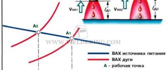
The voltage at the output of the welding machine transformer in the absence of a welding arc (idle mode) is usually 60-80 V. The higher the idle voltage, the more reliably the arc is ignited. The welding arc voltage is usually 1.8-2.5 times less than the no-load voltage.
Attention. It is necessary to constantly remember that in the absence of an arc the voltage at the transformer output is life-threatening.
For welding in everyday life, an electrode with a diameter of 3 mm is usually used, which is sufficient to provide an arc current of approximately 150 A. With an open circuit voltage of 70 V, the arc voltage will be approximately 25 V, and the power consumption P of the welding machine must be at least
Р=25×150=3750 W =3.75 kW.
It is advisable to design the transformer for higher power, that is, higher welding arc current. For example, with an arc current of 200 A, the power consumption will be approximately 5 kW. This is the power the transformer should be designed for.
The single-phase voltage in the house should be 220 V, but it can vary by ±22 V. This is one of the reasons why the arc current may change and will need to be adjusted.
The cross-section of the wire in the secondary winding of the transformer is determined based on the current density equal to 5 A/mm2. For a current of 200 A, the wire cross-section is 40 mm2, that is, it can only be a busbar that is wound with layer-by-layer insulation. Based on existing standard sizes, you can select the required tire both in length and cross-section.
Typical sizes of copper busbars produced by industry:
- length from 0.5 to 4 m with intervals of 0.5 m;
- width from 2 to 60 cm with intervals of 1 cm (with widths from 4 to 10 cm) and with intervals of 5 cm (with widths from 10 to 60 cm);
- thickness from 3 to 10 mm.
You can also use a stranded wire, the cross-section of which corresponds to the calculated value. To increase the cross-section, the wire can be folded in half or three. For aluminum wire, the cross-section must be increased by 1.6-1.7 times.
For a choke that is connected at the output of the transformer, the cross-section of the wire must be the same as in the secondary winding of the transformer.
Diode bridge
Such a device is an electrical device used to convert alternating current into direct current. The phrase “diode bridge” is formed from the word “diode”, which implies the use of diodes in it. The diode bridge rectifier circuit depends on the AC network to which it is connected. The network can be:
Depending on this, the rectifier bridge is called a Graetz bridge or a Larionov rectifier. In the first case, four diodes are used, and in the second, the device is assembled using six.
The first rectifier circuit was assembled using radio tubes and was considered a complex and expensive solution. But with the development of semiconductor technology, the diode bridge has completely replaced alternative methods of signal rectification. Selenium pillars are rarely used instead of diodes.
Device designs and characteristics
Structurally, the rectifier bridge is made of a set of individual diodes or a cast housing with four terminals. The body can be flat or cylindrical. According to the accepted standard, icons on the device body mark the terminals for connecting alternating voltage and the output constant signal. Rectifiers with a housing with a hole are designed for mounting on a radiator. The main characteristics of the rectifier bridge are:
- Highest forward voltage . This is the maximum value at which the device parameters do not go beyond the permissible limits.
- Highest permissible reverse voltage . This is the maximum pulse voltage at which the bridge operates for a long time and reliably.
- Maximum operating rectification current . Indicates the average current flowing through the bridge.
- Maximum frequency . The frequency of voltage supplied to the bridge at which the device operates efficiently and does not exceed the permissible heating.
Exceeding the rectifier's characteristics leads to a sharp reduction in its service life or breakdown of pn junctions. It should be noted that all diode parameters are indicated for an ambient temperature of 20 degrees. The disadvantages of using a bridge rectification circuit include a higher voltage drop compared to a half-wave circuit and a lower efficiency value. To reduce losses and reduce heating, bridges are often made using fast Schottky diodes.
Device connection diagram
On electrical circuits and printed circuit boards, a diode rectifier is indicated by a diode icon or in Latin letters. If the rectifier is assembled from individual diodes, then next to each is placed the designation VD and a number indicating the serial number of the diode in the circuit. VDS or BD labels are rarely used.
The diode rectifier can be connected directly to a 220 volt network or after a step-down transformer, but its connection circuit remains unchanged.
When a signal arrives in each half-cycle, current will only be able to flow through its own pair of diodes, and the opposite pair will be blocked for it. For a positive half-cycle, VD2 and VD3 will be open, and for a negative half-cycle, VD1 and VD4. As a result, the output will be a constant signal, but its pulsation frequency will be doubled. In order to reduce the ripple of the output signal, a parallel connection of capacitor C1 is used, as in the case of one diode. Such a capacitor is also called a smoothing capacitor.
But it happens that the diode bridge is placed not only in an alternating network, but is also connected to an already rectified one. Why a diode bridge is needed in such a circuit will become clear if you pay attention to which circuits use such a connection. These circuits involve the use of radioelements that are sensitive to power reversal. Using a bridge allows for simple but effective foolproof protection. In case of incorrect connection of the power polarity, the radio elements installed behind the bridge will not fail.
Functionality check
This type of electronic device can be checked without desoldering it from the circuit, since no shunting is used in the device designs. In the case of a rectifier assembled from diodes, each diode is checked separately. And in the case of a monolithic case, measurements are carried out on all four of its terminals.
The essence of the test comes down to checking the diodes for a short circuit with a multimeter. To do this, perform the following steps:
- The multimeter switches to diode or resistance vertebrae mode.
- The plug of one wire (black) is inserted into the common socket of the tester, and the second (red) into the resistance test socket.
- With the probe connected to the black wire, touch the first leg, and with the probe of the red wire, touch the third pin. The tester should show infinity, and if you change the polarity of the wires, the multimeter will show the transition resistance.
- The minus of the tester is fed to the fourth leg, and the plus to the third. The multimeter will show resistance; when changing polarity, infinity.
- Minus on the first leg, plus on the second. The tester will show an open transition, and when changing, a closed one.
Such tester readings indicate the serviceability of the rectifier. If you don't have a multimeter, you can use a regular voltmeter. But in this case you will have to supply power to the circuit and measure the voltage on the smoothing capacitor. Its value should exceed the input value by 1.4 times.
Popular posts
- DIY Easter egg for Easter 2022 - 5 best crafts 12 volt DC motor speed controller How to make a boat out of foam How to make welding pliers for spot welding How to build a horse stable Papercraft for beginners, paper modeling, 3D sculptures and simple paper figures for children How to make a bouquet in a box with your own hands: step-by-step instructions Drip irrigation in a greenhouse and in the garden with your own hands
Purpose and practical use
The scope of use of a bridge made of diodes is quite wide. These can be power supplies and control units. It is installed in all devices powered by a 220 volt industrial network. For example, TVs, receivers, chargers, dishwashers, LED lamps.
Cars cannot do without it either. After starting the engine, the generator starts working, producing alternating current. Since the on-board network is all powered by constant voltage, a rectifier bridge is installed through which rectified voltage is supplied. The same constant signal also recharges the battery.
The rectifier device is used to operate the welding machine. True, it uses powerful devices that can withstand currents of more than 200 amperes. The use of diode assembly in devices provides a number of advantages compared to a simple diode. This straightening allows you to:
- increase the ripple frequency, which can then simply be smoothed out using an electrolytic capacitor;
- when working together with a transformer, get rid of the bias current, which makes it possible to more efficiently use the overall power of the converter;
- pass more power with less heat, thereby increasing efficiency.
But it is also worth noting the drawback due to which in some cases the bridge is not used. First of all, this is a double voltage drop, which is especially sensitive in low-voltage circuits. And also, when some of the diodes burn out, the device begins to operate in half-wave mode, which is why parasitic harmonics penetrate into the circuit, which can damage sensitive radioelements.
power unit
Not a single modern power supply can do without a rectifier. High-quality sources are manufactured using bridge rectifiers. The classic scheme consists of only three parts:
- A step-down transformer.
- Rectifier bridge.
- Filter.
A sinusoidal signal with an amplitude of 220 volts is supplied to the primary winding of the transformer. Due to the phenomenon of electromagnetic induction, an electromotive force is induced in its secondary winding and current begins to flow. Depending on the type of transformer, the voltage value is reduced by a certain value due to the transformation ratio.
An alternating signal with reduced amplitude appears between the terminals of the secondary winding. In accordance with the diode bridge connection diagram, this voltage is supplied to its input. Passing through the diode assembly, the alternating signal is converted into a pulsating one.
This form is often considered unacceptable, for example, for sound equipment or lighting sources. Therefore, a capacitor connected in parallel with the output of the rectifier is used for smoothing.
Three-phase rectifier
In production and in places where a three-phase network is used, a three-phase rectifier is used. It consists of six diodes, one pair for each phase. Using this type of device allows you to obtain a higher current value with low ripple. This, in turn, reduces the requirements for the output filter.
The most popular options for connecting three-phase rectifiers are the Mitkevich and Larionov circuits. In this case, not only six diodes can be used simultaneously, but also 12 or even 24. Three-phase bridges are used in diesel locomotives, electric vehicles, on drilling rigs, and in industrial gas and water purification plants.