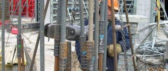
Electroslag welding (ESW) is used for mass vertical joining of metal parts. The method helps to obtain high-quality seams at a low cost. Flux protects the molten material from oxidation and promotes better heating of the metal. The consumable electrode or filler wire is the alloying component.
ESW is used for welding vertical objects.
Features of electroslag welding
The absence of an arc is the main distinguishing feature of this method. Electricity is transferred to the slag, which is considered a conductor. This helps release the heat needed for melting. Before starting work, a special electrode is placed in a container with by-products. The welding method has the following features:
- large distance between parts located vertically;
- lack of contact of the weld pool with oxygen (the entire area remains under slag);
- low flux consumption, alloying the joint with a consumable electrode;
- the seam remains in a liquid state for a long time, facilitating the evaporation of gases.
New opportunities
It is not difficult to guess that electroslag welding, which requires qualified personnel, the use of special equipment and has a number of strict technological restrictions, cannot be carried out at home. Nevertheless, many enterprises actively and quite successfully use this technique. There are several reasons for this.
- With proper organization of the process, the structure of the connecting seam is as close as possible to the structure of the material being joined, which ensures high strength of the finished products.
- This strength is so great that in many cases, electroslag welding technology eliminates the use of complex equipment necessary for casting and forging workpieces, as well as their subsequent processing.
- Compared to other welding methods, material consumption is significantly reduced. This is important because the cost of materials makes up a significant part of the cost of the final product.
The essence of the process
The essence of the technology is to transfer current to the slag, and from it to the electrode and the edges of the parts. The stability of the process is ensured by a constant temperature, which can reach 1900-2000 °C.
Most of the heat enters the weld pool, then the energy flows to the edges of the parts.
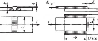
Basic schemes
The electroslag method is used not only for joining parts, but also for casting and surfacing. Welding is performed with consumable electrodes or nozzles, filler rods of large diameter. There are 6 main operating patterns that can be seen in the image.
It is worth considering the features of each option:
- The first 2 methods are considered the most common. They are used to connect workpieces with a height of 2-4.5 cm using an additive with a diameter of 3 mm.
- The third scheme can be used for welding more massive structures. The thickness of each part can reach 12 cm.
- The fourth option is characterized by high performance.
- The fifth scheme belongs to the category of narrowly focused methods. It is used when working with low-alloy steels. The leaf height can reach 10 cm.
- The sixth scheme is intended for creating dimensional structures without further heat treatment. The thickness of the welded workpieces can be up to 6 cm. The method helps to obtain a strong, uniform seam.
Welding process diagram.
Types of Welds and Joints
ESW technology allows you to weld parts located in different spatial positions. The most commonly used types of seams are:
- Butt joints. A small distance is left between the parts, which is considered the main feature of electroslag technology. The procedure for cutting edges and forming welds is regulated by GOST 15164. When butt welding parts of different thicknesses, the thicker edge is thinned. It is possible to weld a metal plate to a less massive workpiece.
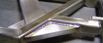
- T-joints and corner joints. They are used less frequently than butt ones. When using a melting tip, the weld edges are cut in a K- or V-shape.
- Straight connections. Performed in a vertical position. A slight tilt is allowed.
- Circular seams. Used when working with spherical or cylindrical workpieces.
We recommend reading: What is automatic welding
Preparing the product for the welding process
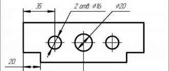
The end of an object with dimensions no more than 20 cm is treated with a gas cutter. The need for this operation arises from the need to correct the ridges and hooks: they must be 0.2-0.3 cm, with a deviation from the right angle of no more than 0.4 cm. The surface of thicker metal products goes through a stage of mechanical action, and all rolled products are cleaned of oxides and corrosion using an emery machine. Casting and forging must be processed using a similar technique, and at a distance of 8 cm from the end.
If there is a need to connect two rolled products with different layers, then a stepped system of sliders is used, or the required layer is removed over the surface of a metal of greater thickness. When fastening ring-shaped alloys, the difference in the diameter of the joint should not be more than 0.5, and the shift should not be more than 1 mm. From the above we can conclude that such actions are of a jewelry nature. But there is another important point here: in order to get a high-quality part, all markings must be done with a slight indentation towards the larger side. This must be done due to the deformation that occurs during exposure to heat.
Areas of application
The technology is considered highly specialized. It is used in shipbuilding and automotive manufacturing, creating bridges and other massive structures. Using ESW, supporting elements of rolling machines weighing up to 100 tons are welded. The technology can be used in electroslag remelting. In this case, the current flows not to the filler wire, but to the material being melted. EHS is not used for:
- work with thin-walled elements that completely melt under the slag;
- formation of multidirectional connections;
- welding parts that are too massive to be covered by sliders.
Technology for performing ESS
The following diagram helps to get an idea of the process technology.
The parts to be welded (1) are positioned so that the required gap is formed between them. Then their relative position is fixed with technological U-shaped brackets (not shown in the diagram), which are welded along the future seam at regular intervals. At the bottom of the gap, an initial (2) is installed, and at the top on the workpieces, output (3) strips are installed, which help to bring the shrinkage cavity of the seam above the level of the finished product. From the outside, the gap cavity is limited by side copper sliders (4).
Flux is introduced into the gap, and an arc is excited between the electrode (7) and the initial bar - it is a source of heat. The released energy melts the flux, a liquid slag bath (5) is formed, the level of which rises and shunts the arc. Now, with an arcless process, the thermal energy is sufficient to melt the materials of the electrode supplied into the gap and the edges of the parts being welded. The molten mass flows down and forms a metal bath (8) under a layer of slag. The flow of metal is prevented by cooled sliders. Further, during the welding process, the level of liquid metal rises, and in the lower layers the melt crystallizes, forming the necessary connecting seam.
Types of Electroslag Welding
The methods differ in the types of filler materials and the methods of their supply.
With electrode wires
The material is selected taking into account the type of welding machine and the characteristics of the metals being joined. The wire enters the space between the parts slowly. It is fed from top to bottom, following the moving electrodes.
Electroslag welding with electrode wires.
With large cross-section electrodes
The welding process uses round or rectangular elements of increased diameter. They are moved closer to the gap as the melt forms. Unlike wire, electrodes with a larger cross-section quickly form a large volume of suture material.
With melting mouthpiece
The technology combines the 2 previous methods. The conductive plates are installed in a position that facilitates rapid heating of the flux. The wire enters the weld pool through the guide nozzle. The method is intended for the formation of curved connections.
Electroslag welding using a nozzle.
General principles
It is easier to understand the essence of electroslag welding if we consider this process in a simplified form. Everything happens as follows:
- The parts to be joined are installed with a certain gap, the value of which varies depending on the size of the product, the chemical composition of the material and the parameters of the welding current. A chemical called flux is placed in this gap and an electrode is applied to it.
- The current supplied to the electrode passes through flux, the composition of which can be different. As a result of heating, a so-called slag bath is formed, inside which the temperature necessary for melting the metal is maintained. Slag, lighter than metal, is always on top, blocking the flow of atmospheric air to the weld formation zone and increasing the cooling time of the molten metal.
- To keep molten materials from flowing out, the processing area is fenced with water-cooled movable sliders made of copper. In some cases, it is possible to use the enclosing plates remaining on the finished part.
Preparatory work
Welding begins with the selection of filler materials and equipment. After this, the parts are prepared for joining.
Selection of welding materials
The types of wires used for ESW can be studied using the table:
| Type of steel | Filler material grade |
| Structural | SV-08A, SV-08GA |
| Medium carbon cast | SV-10G2S, SV-10G2 |
| Boiler room | SV-10G2S, SV-10G2 |
| Medium Carbon Forged | SV-10G2 |
| Low alloy | SV-10G2S, 18ХМА, SV-08-G2S, SV-08ХН2М |
| Medium alloyed | SV-08Х3Г2СМ, SV-20ХН3МФ |
| High alloy | SV-04Х19Н11М3 |
All materials presented in the table can be cooked using fluxes AN-99, AN-8. When joining steels 08Kh18N10T and 25KhN3MFA, grade 48-OF-6 material is used.
Mode selection
The main indicators are:
- current strength, I;
- reduction in voltage between the slag bath and the electrode, U;
- wire arrival speed, Vе;
- speed of electrode guidance, Vst;
- slag bath depth, h;
- wire extension, L;
- electrode oscillation speed, Vk;
- number of rods, n;
- electrode cross section.
Formula for calculating current strength
To calculate the current strength, use the formula I = (0.22Ve 90)n 1.2(Vst 0.48Vp)ab, where a and b are the height and width of the workpieces. The additive feed rate is: Vе= VсвF/S. Indicators Vk, L, h are constant.
Selecting the number of electrode wires
The parameter depends on the dimensions of the workpieces being welded. If the thickness does not exceed 5 cm, work with 1 wire. 2 electrodes are required when the parameter is 5-12 cm. When welding more massive elements, 3 wires are used.
We recommend reading: The nuances of using gas welding
Preparation of products
Before starting work, the ends of the parts are cleaned of rust and oxide film. For this purpose, special grinding machines are used. The edges are given the desired shapes and sizes. It is recommended to install parts with a wedge-shaped gap that increases upward. The opening angle is selected taking into account the method of welding and fixing the workpieces. The indicator is most often 1-2°. The parts are secured with strips or brackets welded along the joint. After welding is completed, the fasteners are cut off using a gas plasma method.
Interesting video
Electroslag welding is based on the release of heat when an electric current passes through molten flux—slag, the electrical resistance of which is many times greater than the electrical resistance of the metal. Melting of the welding wire and the welded metal occurs due to the heat of the molten flux.
For welding in a vertical position, a butt joint without beveled edges is assembled with a mandatory gap of 25-30 mm. Copper forming sliders move from bottom to top along the axis of the joint being welded on both sides. They are connected to the welding machine. On the side opposite the device, instead of the slide, you can install a removable copper plate. The welding wire is directed into the gap between the edges to be welded, for which it is bent with a special bending device or a current-carrying nozzle so that in the welding zone its axis coincides with the axis of the joint.
Flux is supplied to the welding zone from a hopper through a tube in small portions. Melting of the welding wire, base metal and flux occurs in a closed cavity. The bottom of this cavity is the seam, the walls are the edges of the sheets being welded and the walls of the forming devices (sliders), and the lid is a layer of molten flux - slag.
Between the forming devices (rams) and the molten metal there is a thin layer of molten slag. The welding current passing between the welding wire and the metal being welded heats the slag bath and maintains high electrical conductivity and temperature in it, which must be higher than the melting point of the welding wire and the base metal and constant.
The constant temperature of the slag bath ensures the stability of the process. The molten base metal and welding wire metal sink to the bottom of the slag pool and form a metal pool. The metal bath cools fastest on copper slides and forms a seam connecting the parts being welded.
The sliders are cooled by running water, which is supplied and discharged by rubber hoses. The supply of welding wire to the welding zone and the movement of sliders with hoses supplying and discharging water are carried out by a special welding machine. As welding progresses, the apparatus rises, and with it the level of the slag and metal bath, which must remain constant in relation to the slides.
In the case when the level of the bath rises faster than the welding machine moves, and with it the sliders, slag and molten metal may overflow over the edge of the slider. If the slider rises faster than the bath level, then liquid metal will inevitably flow out from under the slider. The level of the slag and metal pool will remain constant only at a constant speed of movement of the welding machine and feed of the welding wire, as well as at a constant gap between the welded edges. When the gap fluctuates, a change in the level of the weld pool is inevitable.
Changing the level of the metal bath leads to a change in the depth of the slag bath, the top of which is at the level of the upper edge of the slide, and the bottom is limited by the upper surface of the molten metal. The stability and nature of the welding process, as well as the quality of the weld, largely depend on the depth of the slag bath. To maintain a constant level of the weld pool, electroslag welding machines are equipped with a circuit for automatically maintaining the level of the pool.
In electroslag welding, a metal pool is formed by welding wires, plates, thick rods, a fusible nozzle and the metal of the welded product. Depending on which of the listed materials serves as the electrode, there are four methods of electroslag welding.
1. Electroslag welding with one or more welding wires is the most common method. According to the scheme, you can weld metals up to 50-60 mm thick. With a larger thickness, the welding wire nozzle is given oscillatory movements from slider to slider, the cross-section of the welding wire is increased or the number of wires is increased. The wire can be used to weld metal with a thickness of 20 to 600 mm of any length.
Read also: Do-it-yourself sand for sandblasting
2. Electroslag welding with one or more plates or rods of round, square or any other cross-section. It is used mainly when the thickness of the metal being welded is significant and the length of the seam is no more than 1-1.5 m. With this welding method, the welding machine does not have nozzles or a mechanism for feeding the welding wire. The plate, which serves as the electrode, is fixed in a welding machine, which moves down as the plate melts. The advantages of this method are: simpler design of the welding machine; simpler welding technique; the possibility of using plates or rods from materials from which it is impossible or very difficult to make wire, such as, for example, cast iron.
3. Electroslag welding with a fusible nozzle is a combination of the two previous methods. In this method, the fusible plate is a fusible mouthpiece, which has the same outline as the cross-section of the product being welded. The mouthpiece has channels that serve to guide the welding wires. If, when welding with a plate or rod, they are lowered into a slag bath as they melt, then the fusible nozzle is fixed in the gap between the edges being welded. The seam consists of the metals of the product being welded, a fusible nozzle and welding wires. A fusible nozzle, which serves to guide welding wires, supply current to them and as a filler metal, is usually made from a set of plates, rods and tubes in which channels are created for the passage of welding wires. The cross-section of the mouthpiece ranges from 10 to 50% of the cross-section of the gap between the parts of the product being welded. The formation of a metal and slag pool at the beginning of welding is due to the melting of the welding wires, and only after the slag pool reaches the lower end of the fusible nozzle does it also begin to melt. Electroslag welding with a fusible nozzle is used mainly when welding products with a complex cross-section and a short seam length.
4. Electroslag butt welding (resistance-slag) differs from the previous ones in that a metal pool is formed by melting the ends of the parts being welded, i.e., without the use of filler metal. When current passes through the slag bath, the ends of the parts being welded are melted. After a metal bath has formed above the lower part, the parts are brought together, and the slag is squeezed out of the gap between them. The welding current is turned off after the parts are brought together or before the approach begins.
On an industrial scale, the ESW method is used for vertical joining of metals. Electroslag welding allows you to obtain a high-quality connection at minimal cost. Flux not only protects the melt from oxidation, but also provides heating of the parts. The electrode or welded wire acts as an alloying metal, containing up to 20% additive in the melt. It fills the gap between the connected elements, forming a dense seam of a homogeneous structure. It is worth saying in more detail about the features of EHS, advantages and disadvantages.
Electroslag welding technology
The process of melting the edges of parts begins after flux is supplied to the weld pool. The treated area is heated to the desired temperature. There are 2 methods for creating a slag bath:
- Solid start. Melting begins due to the burning of an electric arc. The desired characteristics of the bath are maintained by adding slag.
- Liquid start. Molten flux is fed into the working area. The material is preheated in an oven.
Scheme of the ESW process.
When using the first method, increased energy consumption is observed due to the need to increase the current strength. The bottom of the bar must be covered with metal powder required to initiate the arc. During the process, you need to monitor the condition of consumables and add them regularly.
Look to the root
The essence of the process is that a special chemical composition - welding flux - is placed into the prepared gap between the parts being connected, which is acted upon using an electric arc. As a result of heating, the flux melts, turning into slag, which protects the processing area from exposure to atmospheric air. When using this technology, the molten metal cools slowly, which creates favorable conditions for the formation of a high-quality structure of the connecting seam. It is quite difficult to understand what electroslag welding is by watching a video. Indeed, in this case, the audience gets an idea only of the external side of the process.
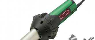
Equipment used
Most often, the A535 machine is used for welding using the electroslag method. It works with alternating current and is suitable for creating longitudinal or circular seams with a width of no more than 30 cm. The device has the following technical characteristics:
- thickness of welded workpieces – up to 45 cm;
- power supply – connection to a 380 V network;
- number of electrodes – 3;
- current frequency – 50 Hz;
- filler wire diameter – 3 mm.
The A550 machine is used less frequently. Welding is carried out in the same way as when working with the previous unit. However, the technical characteristics of the machines are somewhat different. In A550, the stroke height of automatic sliders is set, depending on the thickness of the parts.
Welding methods
Electroslag welding is not suitable for all metals, but its scope of application cannot be called narrow. It is usually used to join low-carbon and medium-carbon steels, cast iron, non-ferrous metals (up to titanium and aluminum), and less often for alloy steels.
They are used in the production of massive, large-sized parts (thickness about 100-600 mm), and in waste remelting.
In practice, 3 main welding techniques are used. The first involves the continuous supply of a filler electrode directed in a horizontal plane into the melt. The movement of the electrode is reciprocal in nature to ensure maximum contact density.
The second electroslag technique is welding with large plate electrodes, which actually replace copper sliders.
In this case, the additive is used to a lesser extent - the electrodes themselves tightly close the gap and provide an effective melt: the ends of the parts are connected without an additive. But in this case, the electrodes must be adjusted in shape to the parts; this is a highly specialized method.
The third technique is based on combining the first two. It contains both a plate electrode and a special consumable electrode. The first remains stationary during the entire electroslag welding process, the second is fed into the melt zone and is, in essence, an additive.
Please note that the chemical composition of the additive must be similar to that of the base metals.
There are also two different operating principles for electroslag welding installations. Devices that implement the first method work with a solid slag mixture, which they independently melt. Installations operating on the second principle use a liquid mixture pre-melted in an oven.
The first ones require a more powerful starting current to start working, because a lot of energy is spent on bringing the slag to a liquid state. The latter, accordingly, requires a nearby smelting furnace.
Quality control
The appearance of defects deteriorates the quality of the welded joint, making it less durable. Special methods are designed to detect deficiencies.
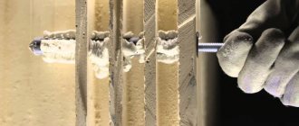
How is quality control of welded joints carried out?
Characteristic defects
When working using ESW technology, welded joints may acquire the following disadvantages:
- Hot cracks. Occurs when working with any type of steel. However, high-carbon alloys are most susceptible to cracks. High welding speed with rigid fixation of parts also contributes to the appearance of defects.
- Cold cracks. Appear when connecting workpieces made of medium-alloy steels with a ferrite additive. Reducing the depth of the bath and uniform penetration of the joint help prevent the appearance of defects.
- Other defects. These include foreign inclusions, pores, and lack of penetration. Appear when welding rules are not followed.
We recommend reading: How to weld metals in a gas-protective environment
Methods for controlling welds
Compounds obtained as a result of ESW require comprehensive research. The following control methods are used:
- visual inspection;
- ultrasound scanning;
- magnetic flaw detection;
- X-ray control;
- radiation flaw detection.
Ultrasound scanning of seams.
Where is it used?
The main area of application is heavy engineering.
Possibility of use:
- connection of thick-walled sheets and parts (armored hulls of ships, shafts of hydraulic turbines, frames of powerful presses and rolling mills, armor of tanks, drums of high-pressure boilers);
- welding of metals having different chemical compositions;
- construction of domain casings;
- production of welded-forged and welded-cast structures;
- production of metallurgical equipment, thick-walled cylinders.
The method is also used for welding metal of small thickness (14-30 mm), for example, installation joints of ship hulls on a slipway.
Advantages and disadvantages
The positive qualities of the technology include:
- Protection of the metal from oxidation. There is no need to use argon or other gas.
- Uniform heating, slow cooling of parts. The temperature rise starts from the flux layer. The slag coating maintains a stable heating level. This has a positive effect on the quality of the seam.
- Minimal influence of current on the connection formation process. Warming up occurs not due to the arc, but due to the slag. Melting does not stop after disconnecting the machine from the power supply.
- Possibility of welding thick parts in 1 pass. There is no need to form multilayer seams. When using 2 electrodes, workpieces thicker than 20 cm can be connected.
- Minimum slag consumption. The volume of the material does not exceed 5% of the mass of the metal. A small amount of energy is expended. There are no losses inherent in other welding technologies.
- High efficiency. With a minimal investment you can perform extensive welding work.
- Automation of most welding processes.
- Reducing the duration of the preparatory stage. It is not necessary to trim the edges. The gap between the parts is filled with melt.
The disadvantages of the method include:
- the impossibility of forming certain types of seams (only vertical or similar connections are made using the ESW method);
- continuity of the process;
- granularity of the root layer, reducing the strength of the seam.
Advantages
Electroslag welding has a number of undoubted advantages that cannot be neglected when organizing production processes.
- The ability to ensure a stable and high-quality seam structure when connecting parts of significant mass and thickness.
- There is no need for preliminary chamfering of the edges and subsequent processing of the finished product to remove slag.
- In the case of simultaneous use of several electrodes, it becomes possible to apply a welding seam along the entire length in one pass, which significantly reduces work time and speeds up production.
Additional Information
Seam parameters (width, depth, appearance) can be changed using one or another mode. The main factors are considered:
- electrode installation locations;
- welding speed;
- number of electrodes;
- electrical parameters.
Additional values must be set in accordance with the main ones. The slightest changes are reflected in the properties of the seam. At a low specific current intensity, electroslag welding proceeds stably. It can be used to connect rods to metal sheets.
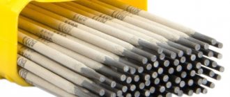
What fluxes are used?
Fluxes and slags for electroslag welding are one and the same. This substance is the leading one, and it must meet certain conditions:
- ensuring the start of the reaction in the shortest possible period of time and with any voltage;
- edge penetration at a high level;
- high attributes and strength of the finished seam;
- ease of cleaning up excess upon completion of actions.
Also, for each procedure you need to choose your own type of substance. For example, AN-8 is intended for low-alloy or carbon types of iron. Its calcination modes are 400-500 °C. The chemical composition of the granules includes oxides of silicon, manganese, calcium, magnesium, and aluminum. The weld metal will contain 0.12% phosphorus and 0.1% sulfur.
AN-22 is intended for high-alloy materials. This matter is similar to a glassy structure of yellow color. As for the calcination mode, it should reach 650-800 °C.
Flux for electroslag welding
When processing stainless steel, fluxes AN-45 and its analogues are used. However, when this substance melts, a large release of fluoride gases is observed, which is the main disadvantage. Technological properties are as follows:
- Good seam formation with a smooth transition to the base of the product.
- Low tendency to chip and crack formation.
- The grain size can be 0.25-3.0 mm.
- Satisfactory definition of the slag crust.
There are also less popular varieties. For example, AN-9, ANF-1, ANF-7. Each of the components differs in chemical composition, melting point and appearance, which must also comply with GOST.