Machining of internal cylindrical surfaces
TO
category:
Turning
Machining of internal cylindrical surfaces
Next: Machining external and internal conical surfaces
The holes can be through, blind, normal and deep with a length exceeding five hole diameters. Depending on the type of hole, its size, accuracy and roughness parameters of the machined surface, drilling, reaming, boring, countersinking, reaming, lapping and rolling (flaring) are used to process the hole.
Rice. 1. Rights of workpieces
Rice. 2. Typical errors when sharpening and installing a slotting and e) cutting tool
Holes with a diameter of 30-60 mm are rolled out using a ball and roller rolling machine. In this case, the hole diameter increases by 0.02–0.03 mm. The ball rolling head has a mandrel, a thrust bearing and cone rings. The ring moves along the axis of the mandrel and is pressed through the ring by a spring, the compression of which is regulated by a nut with a lock nut. The processing balls are located in the separator and are located at an angle of 120° relative to each other. The qualities and parameters of the machined hole surface are given in the appendix. A holder with a conical shank and a rolling mandrel is connected by a pin.
Depending on the requirements for the accuracy of machined holes and their diameters, different types of tools are used.
To drill holes when processing workpieces made of medium-hard materials, spiral drills with a cylindrical and conical shank are used; when processing workpieces made of materials of increased hardness - solid carbide drills or drills equipped with carbide inserts.
Rice. 187. Grinding a thread in one working stroke
Rice. 188. Scheme for processing wide grooves
When drilling holes in cast iron workpieces with a depth of no more than two or three drill diameters, a drill with straight flutes is used. When drilling, prefabricated drills with multifaceted, non-sharpenable plates are usually used. When drilling deep holes, single-sided cutting drills are used. When drilling holes with a diameter of more than 50 mm in solid material, ring drills are used.
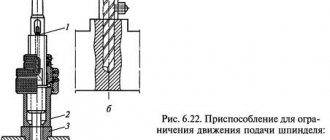
When drilling holes, the drills are installed in the tailstock quill or in the tool holder. In this case, a fastening device is used that allows you to work with both manual and mechanical feed. Before installation, drills with a cylindrical shank are secured in a drill chuck, which is installed in the tailstock quill. Drills with a conical shank are installed in the tailstock quill using adapter bushings having a Morse taper. When processing, drills must be installed strictly along the line of centers.
Rice. 189. Processing of the end surface and ledges
When processing a hole longer than two diameters, first drill it with a short drill and then with a long one. It is not allowed to drill a hole that is deeper than the length of the spiral flute of the drill. When drilling blind holes, use the scale marked on the tailstock quills. If there are no marks on the quill, a scale ruler is applied to the quill to determine the drilling depth. When drilling holes, you must use coolant. When the drill becomes dull, a peculiar grinding noise appears. The greatest wear of the drill is observed at the corners of the ribbon.
Rice. 190. Scheme for processing ledges using stops and a floating center
Rice. 191. Checking the location of the ledges
Rice. 192.
Rice. 193. Allow for processing of ends
Rice. 194. Trimming the end with a bent and ledges with a scoring tool
A hole with a diameter of over 30 mm is processed in two working strokes. First, drill with a drill d - = 25 mm (Fig. 200, g), and then drill out with a drill of the required diameter (Fig. 200, h). You cannot drill a hole in a casting or forging. Such holes are bored. Holes whose depth exceeds the diameter of the drill by 10 times or more are drilled with the supply of coolant (Fig. 200, i).
The holes are bored using boring cutters. The sharpening angles for boring cutters are the same as for cutters for external turning, with the exception of the rear angles, which have larger values. The smaller the hole diameter, the larger the clearance angle a should be. The protrusion of the cutter from the tool holder is increased by 5-10 mm to the depth of the boring hole. When boring, the depth of a blind hole is determined by the stop, mark, vernier (Fig. 201, c). During rough boring, the cutter is installed slightly below the center line, and during finishing boring, it is installed slightly above the center line of the hole (Fig. 201, d). When attaching thin-walled bushings to a chuck, deformations may occur in them (Fig. 202). Distortion of the hole shape can be detected using an indicator bore gauge having three touch points (Fig. 203).
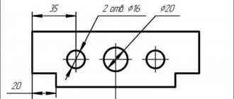
Rice. 195. Types of holes
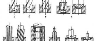
Rice. 196. Hole making tools
Compared to boring cutters, countersinks have greater strength, so processing with them can be carried out with a higher feed and depth of cut. For countersinking holes with a diameter of up to 35 mm, countersinks with three cutting edges and a conical shank are used. For countersinking holes with a diameter of up to 100 mm, mounted countersinks mounted on a mandrel are used.
During final processing, the hole is reamed. The reamer is installed exactly along the axis of the hole being machined. The reamer is mounted in a hinged device. Depending on the required accuracy, one or more reamers are used for reaming (roughing 1 and finishing 2).
To obtain the surface of holes of the 5th and 6th accuracy grade at = 0.16...0.05 mm, laps are used. In this case, it is necessary that the hole is pre-processed to 6-8 quality and has Ra = 1.25...0.2 mm.
Rice. 197. Sequence of using tools for drilling, boring and reaming holes
Technical conditions for the manufacture of the foundation.
For normal precision machines: Soil bearing capacity 5kg/m2. If necessary, load the foundation with an additional load (concrete blocks, blooms, etc.) exceeding the weight of the machine by 3-4 times and check the elevation marks with a level on a benchmark not connected to the foundation every day until the end of shrinkage.
Related article: Telescopic floor formwork
For high-precision machines: The foundation must be made with free side edges and heavy concrete of design grades must be used with a compressive strength of 150-200 kg/cm2. To fill the foundation, use a concrete mixture with a volume ratio of cement-sand-crushed stone of 1:1:3 (concrete grade not lower than M250). Foundation depth H > 0.6 √F, where F is the area of the foundation. The foundation is reinforced with a single lattice along the length, width and height with a cell size of 200 mm. The diameter of the reinforcement depends on the size of the foundation and can be from 12 mm to 20 mm.
Strength of foundation concrete. Installation of the machine can be allowed when the concrete reaches a compressive strength of at least 50% of the design strength (approximately corresponding to seven-day concrete). By the time the machine is started, the concrete strength should be at least 70% of the design strength (approximately equivalent to 15-day concrete). The period for complete hardening of concrete is 28 days. The quality of concrete is controlled by the strength of control cubes 200x200x200 mm. The strength of concrete in a finished foundation can be roughly estimated by sound and impact.
Important selection factors
Mechanical processing of parts according to drawings
The choice of shaped cutters is determined by three main criteria:
- The rake angle is formed based on the target materials. In many cases it is 0-25°. Moreover, the size of the angle should be directly related to hardness.
- The clearance angle depends on the type and shape of the cutter. Its value has an inverse relationship with the strength of the cutting edge. Therefore, shaped tools with a large clearance angle are not suitable for processing thick workpieces. For round models, for safety reasons, its value is not made more than 10-15°. For other types of shaped cutters it is up to 30°.
- In most cases, materials are selected from carbide of the highest density. This is caused by high temperature of the edges with simultaneous mutual action with several points due to high resistance.
Subtleties of the turning process
Separately, attention should be paid to turning shaped parts, when transverse and longitudinal feed is applied in parallel, carried out manually by the machine operator.
This method of machining is used if it is necessary to produce a small batch of parts or the surface being processed is small in size. As for the first case, it is unprofitable to produce a conventional shaped cutter from an economic point of view, and to implement the second option you may need a tool with non-standard dimensions, which causes difficulties in operation (for example, vibration generation).
To remove the required layer of metal from the workpiece, either a finishing or a through cutter is used. The longitudinal slide moves to the left, and the transverse slide moves to the right and back. If it is necessary to process a surface characterized by small dimensions, then the longitudinal feed is realized by means of a support, which is installed in such a way that its guides are parallel to the center line of the equipment. Transverse feed in this case is carried out by the transverse slide of the caliper. The tool tip, regardless of the processing method, moves along a curve.
Processing parts with shaped surfaces is a rather complex task that requires certain skills and experience from the machine operator. Highly skilled turners prefer to use automatic longitudinal feed, while simultaneously performing cross feed manually. These processes can be fully automated using special copying devices. Their use is especially important when processing large batches of parts. Go to list of articles >>
Types of shaped cutters and their main characteristics
A shaped cutter, in essence, is a tool whose cutting edge exactly repeats the profile of the surface being processed, that is, it has a curved or stepped shape. The main types of such cutters are presented in Figure 1. These are tools that are intended for the manufacture of shaped parts.
Figure 1. Basic types of shaped cutters
In the picture below, "a" is a rod cutter used to produce a concave surface. Its advantages boil down to simplicity of design and low cost of production. As for the disadvantages, the most significant is the rapid wear of the tool. After a certain number of resharpenings (performed along the front surface so that the profile can be maintained), the plate wears out, due to which the center height, determined when securing the tool, becomes unacceptably small. It follows from this that such a cutter cannot carry out further processing. For this reason, rod cutters are most often used in industries that are not mass-produced.
Under the letter “b” in the same figure there is a prismatic cutter. Its front surface represents the end part of the block used in the production of this tool. In this case, the relief angle is formed due to the inclined position of the cutter 1 in the holder 3. For such a connection, both of these elements are equipped with special grooves made in the shape of a dovetail. Moreover, the holder is slightly notched, so it compresses more and more as screw 2 is tightened, thereby guaranteeing reliable fixation of the cutter. The main “disadvantages” of this type of shaped cutter are related to the difficulties of its production.
You can also familiarize yourself with the disk shaped cutter by looking at Figure 1 (it is located under the letter “c”). The image shows that the rake face of the tool is slightly lower than the axis. This value is designated h and is a tenth of the cutter diameter. Due to this arrangement, the required rear angle is formed and in most cases it is equal to 12°, and the rake angle is 0°. This design does not cause difficulties in the manufacture of the instrument. In addition, it prevents the cutter from being pulled into the workpiece, and thanks to this, the resulting surface is characterized by excellent quality. The width of the disc cutter, as a rule, does not exceed 40 mm, although in some situations it reaches 100 mm.