Modern welding work is carried out using special inverters. Previously, conventional transformers, which are characterized by lower efficiency, were used for such metal processing. The schematic diagram of a welding inverter may differ slightly, but they are all characterized by lightness and compactness. Only by taking into account the design features can the welding inverter be repaired and fine-tuned.
Elements of the electrical circuit of welding inverters
The electrical circuit diagram of an inverter welding machine involves a combination of several elements that are interconnected. The main ones can be called:
- The block responsible for supplying energy to the power section. This element is represented by a combination of several devices that are capable of changing current parameters to the required values. Typically, a capacitive filter and a rectifier are included.
- The device includes a power transformer. The power supply of the welding inverter also includes a 4n90 transistor.
- A separate element is responsible for powering the low-current part of the structure.
- To control the main parameters, a PWM controller is installed. It is represented by a combination of a load current sensor and a transformer.
- A separate block is responsible for protecting the structure from heat. When electrical current passes, some components may become very hot. Therefore, an additional cooling module is installed, represented by a fan and a temperature sensor.
- Control units that allow you to set basic parameters, as well as display elements.
Example of circuit diagram for current 250A
The diode bridge equipment for the welding machine is manufactured and installed taking into account the power of the device and some other points. Each device has its own characteristics, which we will consider in detail below.
Pulse converter
At the output of the rectifier module, an increased voltage of 310 Volts is supplied to the section of the circuit with transistors.
They act as pulse switches in the welding inverter. The main functional purpose of transistors is to ensure switching of the voltage supplied to them in order to obtain a rectangular pulse signal with a frequency in the range from 60 to 80 kilohertz.
Key transistors, as well as diode bridges, are always mounted on radiators that provide the possibility of their constant cooling. To protect these elements from overvoltage, the circuit includes special damper RC circuits. The operation of the remaining converter modules of the welding inverter should be considered separately.
Swaris device diagrams
The welding machine Svaris 200 is characterized by ease of use and low cost. Already the Swaris 160 models had high performance characteristics, and the new version was improved. The circuit of the inverter welding machine determines the following operational characteristics:
- The maximum consumption is 5 kW.
- Welding current can vary from 20-200 A.
- The open circuit voltage indicator is 62 V.
- Efficiency rate 85%.
- Recommended electrodes 1.6-5.0.
In general, we can say that the inverter is made according to the classical scheme, which was discussed above.
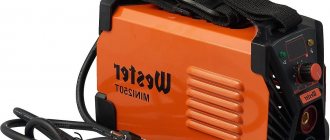
Schemes of models MMA-200 and MMA-250
The MMA-200 and MMA-250 models are widely used. These inverters are almost identical, the only difference is the following points:
- The MMA 250 welding inverter circuit provides for the presence of 3 field-type resistors in the output stage. All are connected in parallel. The MMA 200 welding inverter circuit indicates only the presence of two resistors.
- The new version has three pulse transformers, while the old one only has two.
The basic design of both models is almost completely identical.
MMA-200 inverter circuit
Manufacturer information
In the fall of 2007, a new brand of welding equipment ProfHelper was presented to the Russian tool community at the international exhibition INTERTOOLS.
A project was launched to unite products from various segments of the welding market under a single brand. Based on many years of experience in sales of world brands, the most successful models were taken as the basis for the basic range. Carefully, over the course of several months, production facilities were selected where it was planned to produce goods under the ProfHelper brand. The most important criterion for this selection was the presence of an ISO 9001 certificate, which regulates quality management at enterprises.
Currently under the ProfHelper
two model lines of welding inverters are produced: Prestige and DaVinci, a line of semi-automatic welding machines EuroMig, welding accessories, welding wire for MIG-MAG welding, flux-cored wire (FCAW), welding electrodes, a line of charging and starting devices Invik and EuroStart for charging car batteries and starting cars in the cold season. There are more than 100 positions in total!
The ProfHelper brand aims to cover one of the broad market segments - household and semi-professional welding. The latest technologies, affordable prices and high quality have made the ProfHelper brand
incredibly popular. And the presence of charging and starting devices in the proposed range indicates plans for the development of the brand in other areas of the tool segment besides welding.
Inverter 3200 and 4000 circuits
For manual arc welding, you can use the Inverter 4000 or 3200. Both machines have an almost identical design, which provides the following functions:
- Protection against electrode sticking effect.
- Protecting key components from severe voltage surges.
- Control of basic arc parameters.
- Built-in cooling element with control sensors.
During the manufacture of inverters, IP21 protection was provided. The power of the device is 5.3 kW, powered by a standard power supply network. The detailed diagram of inverter 3200 pro determines the very attractive properties of these models, due to which they have become widespread.
Schemes of other models
As previously noted, almost all inverters operate on a similar principle, and the created circuits may differ insignificantly. All welding machines are divided into several main groups:
- To carry out electric arc welding when using electrodes coated with a special composition, MMA type equipment is used. This scheme is characterized by high efficiency, and the design is light in weight.
- To use refractory electrodes, MMA+TIG welding equipment is used. They can operate in an environment of inert gases.
- On production lines there are units with semi-automatic bar feeding. In this case, work is usually carried out in an environment of inert gases or in special baths.
- For forging or other repairs, spot welding is used.
The ARC 160 model, the circuit of which is quite complex, can be used for a wide variety of work. Unlike the arc 140, the new model's circuit has no major drawbacks.
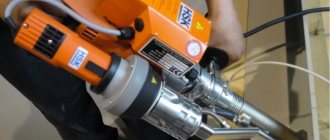
Welding inverter TORUS 250
The Torus 250 version consists of the following elements:
- A clock type generator built on a TL microcircuit. It is worth considering that the powerful inverter circuit does not provide for the use of PWM, but the microcircuit has two comparators with thermal protection sensors.
- The protection system and control module are made on the basis of LM. The sensor that determines the current parameters is placed on a ferrite ring with a winding.
- The circuit also includes two output drivers built on IR
A separate category includes a welding inverter circuit using thyristors, which has become very widespread.
Repair of Torus 250 should be carried out by opening the structure and visually inspecting the main elements. In this case they are as follows:
- The output type rectifier is represented by a separate board on which two radiators are placed. They serve as a base for placing diode assemblies. The module also includes one transformer and a choke. The number of elements in the output rectifier largely depends on the specific assembly.
- The switch module is represented by four transistors in each of the four groups. In order to reduce the degree of heating, they are all placed on separate radiators, which are insulated with special gaskets.
- A powerful diode bridge is used as the output rectifier. In the case under consideration, it is located at the bottom of the structure. This model is equipped with an extremely reliable and practical bridge, which is difficult to burn if the cooling system is working properly.
- The control chip is the main design element. As a rule, the durability of the entire device depends on its correct operation. You can check the unit yourself only if you have a special oscilloscope and the appropriate skills to work with it.
- Housing with cooling fan. As a rule, the cooling unit fails only in the event of mechanical impact.
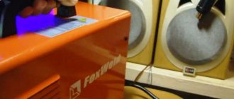
Equipment lines
FoxWeld presents several model lines at the same time. Each of them has its own specific characteristics and has found its own consumer. The most popular are Svaris, Summer Resident, Master, Corundum and Varteg.
The Swaris welding machine is manufactured in China under the direct control of the entire process by Italian developers. Despite the fact that at one time there was a certain distrust of goods from the Middle Kingdom, Svaris devices made it possible to destroy this established stereotype.
Svaris 158 Combi
The inverter semi-automatic Svaris combi is designed to operate in MMA mode, that is, for welding with consumable electrodes. It switches to wire welding mode, which is why it is considered combined. Naturally, the device allows you to work in a protective gas environment.
The body has a built-in wire feed mechanism, so the welding machine, despite its functionality, remains compact. Its weight is only 11 kg. Such a semi-automatic device costs 23,000 rubles.
Svaris 158 is powered by a 220 V household network. It is suitable for minor household repairs, but many professionals use it for larger-scale work. Due to its compactness, the device allows welding work in places with limited spatial conditions.
Model 220
For those who are looking for a budget option for a compact welding machine, the manufacturer presents a device for manual arc welding. This type of work is considered the most popular, which is why Svaris 220 is in demand among amateurs. In a household, especially for the owner of a private house, there will always be work related to the use of welding.
Expert opinion Bagrov Viktor Sergeevich Welder of the highest 6th category. He is considered a master of his craft, knows the intricacies and nuances of the profession.
An excellent option for amateur welders. With such a device, you can easily find work around the house: welding shelving in the garage, attaching an antenna or ground loop to the roof, or whatever.
The device is powered by a 220 V network and can increase the current to 220 A, which is quite enough to cook with electrodes with a diameter of 5 mm. The delivery set, which costs 9,500 rubles, includes an electrode holder and a ground clamp. The body of the device is equipped with a convenient handle that allows you to carry it around the site. Mobility often plays a decisive role, as it is necessary to carry out work at heights or in hard-to-reach places.
Due to the fact that the device is adapted to low voltage and exhibits stable operation, it is valued by residents of the private sector, where the network parameters are far from nominal.
160
Svaris 160 is considered the most affordable welding machine for direct current work. The inverter has a number of advantages over transformer devices, which are practically no longer used today. The transition to new technologies has made it possible to significantly reduce the dimensions of the device, its weight, and increase efficiency and efficiency. It is noted that the quality of the work performed has not deteriorated.
The weight of the welding machine Svaris 160 is 5.5 kg. A similar device can be purchased for 5,500 rubles, but it comes without additional accessories, without a holder and power cables.
Svaris 140 (in case)
An excellent combination of compactness and functionality is embodied in the Svaris 140 model. The design of the device is based on the separate arrangement of the power unit and the control unit. This approach made it possible to increase reliability indicators.
Although the device is positioned as a household device, many note that its performance is in no way inferior to its industrial counterparts. Continuous welding time at maximum current is 4 minutes. There is no need to fear that the installation will fail, since the thermal protection will work, but you should control the time.
The plastic case reliably protects the welding machine from dust during storage and transportation. To prevent dirt or dust from getting on the control unit and power unit, they are separated by special partitions. The cooling system is of a forced type, and the fan speed can vary depending on the temperature.
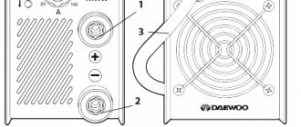
Scheme of welding inverter ASEA-160D
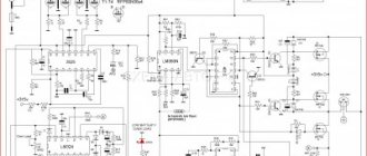
The welding inverter circuit is a highly efficient portable welding machine ASEA-160D manufactured in South Korea. The device is assembled in a small-sized shock-resistant housing. The small-sized inverter ASEA-160D is an excellent choice for specialists involved in metal welding on a professional basis.
Schematic diagram of the inverter welding machine ASEA-160D
Click on the picture to enlarge
It will also be an ideal addition to the technical equipment of your home workshop. Even an inexperienced beginner can master the process of performing welding work on this machine in a short time. Moreover, the inverter is able to work with almost all metals and alloys, using the entire range of current strength.
ASEA inverters from the inside
A very important criterion for a welding inverter is the ability of the electric arc to form a high-quality weld. In addition to all of the above, during the formation of a weld there is virtually no spattering of molten metal, the formation of pores and cracks in the welds.
Distinctive features of ASEA inverters
- Smooth and stable welding arc
- The device is equipped with a built-in module for automatically reducing the voltage at the output terminals of the housing during idle operation to 8v.
- Excellent adaptation of the equipment and its ability to operate with a significant difference in mains voltage in the range of 150v - 270v.
- The welding inverter circuit provides an indication in digital format, which displays the strength of the set current during setup.
- Excellent arrangement of components inside the case, use of high-quality components, competent assembly.
- Ability to weld metal using shielding gas.
These kinds of parameters largely contribute to the ASEA-160D welding inverters and more modern models, which have long held leading positions in Russia among competitors.
The ASEA-160D welding inverter circuit is capable of performing work under the following conditions:
- operating temperature range from – 14°C to + 42°C;
- the percentage of moisture in the air should not exceed 80% at + 22°C;
Technical specifications:
It is strictly not recommended to carry out welding work in conditions where the air is heavily saturated with dust. It is also prohibited to operate in an explosive environment, in rooms with various vapors and gases that contribute to corrosion of the metal structure and insulation.
The circuit of a welding inverter is fundamentally different from the design of its predecessor, the welding transformer. The basis of the design of previous welding machines was a step-down transformer, which made them large and heavy. Modern welding inverters, thanks to the use of advanced developments in their production, are lightweight and compact devices characterized by wide functionality.
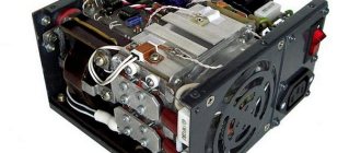
Welding inverter without cover
The main element of the electrical circuit of any welding inverter is a pulse converter that generates high-frequency current. It is thanks to this that the use of an inverter makes it possible to easily ignite the welding arc and maintain it in a stable state throughout the welding process. The welding inverter circuit, depending on the model, may have certain features, but the principle of its operation, which will be discussed below, remains unchanged.
Company
Modern economic relations between countries now have a slightly different format. Many enterprises unite, working for the benefit of one brand. It is much more profitable to set up production abroad with your own brand than to sell finished products. Due to this situation, confusion often arises regarding the country of origin.
FoxWeld is considered a striking example of an international company. This is a trading and production company that is well known in the welding equipment market in Russia, Europe and Asia. The company specializes in the production and supply of welding machines, consumables, and protective equipment.
One of the key principles of the company is to expand the range of supplied products. Only with a wide range can you compete in the welding equipment market. In particular, the manufacturer is trying to fill the segment of professional devices used in production
Particular attention is paid to high quality and the constant introduction of innovative technologies
The features of welding machines include their efficiency and environmental safety. Several sales offices have been opened in Russia. Service support and maintenance covers the Central Federal District, Northwestern Federal District, Southern Federal District, Republic of Crimea, Volga and Ural Federal Districts.
What does the design of a welding inverter include?
The welding inverter circuit, which determines its technical characteristics and functionality, includes such mandatory elements as:
- a unit that provides electrical power to the power part of the device (it consists of a rectifier, a capacitive filter and a nonlinear charging circuit);
- power part, made on the basis of a single-cycle converter (this part of the electrical circuit also includes a power transformer, a secondary rectifier and an output choke);
- power supply unit for elements of the low-current part of the electrical circuit of the inverter apparatus;
- PWM controller, which includes a current transformer and a load current sensor;
- a block responsible for thermal protection and control of cooling fans (this block of the circuit diagram includes inverter fans and temperature sensors);
- controls and indications.
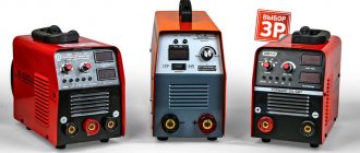
What types of inverters are available on the modern market?
For a certain type of welding, you should choose the right inverter equipment, each type of which has a specific electrical circuit and, accordingly, special technical characteristics and functionality.
Inverters produced by modern manufacturers can be used equally successfully both in industrial enterprises and in everyday life. Developers are constantly improving the electrical circuit diagrams of inverter devices, which allows them to be equipped with new functions and improve their technical characteristics.
The number of connectors and controls on the front panel speaks volumes about the capabilities of the welding inverter
Inverter devices as the main equipment are widely used to perform the following technological operations:
- electric arc welding with consumable and non-consumable electrodes;
- welding using semi-automatic and automatic technologies;
- plasma cutting, etc.
In addition, inverter machines are the most efficient type of equipment used for welding aluminum, stainless steel and other difficult-to-weld metals. Welding inverters, regardless of the features of their electrical circuit, allow you to obtain high-quality, reliable and neat welds made using any technology
At the same time, what is important is that the compact and not too heavy inverter machine, if necessary, can be easily moved at any time to the place where welding work will be performed
Mobility is one of the advantages of inverter devices
How does a welding inverter work?
The formation of a high current, with the help of which an electric arc is created to melt the edges of the parts being joined and the filler material, is what any welding machine is designed for. For the same purposes, an inverter apparatus is also needed, which allows the generation of welding current with a wide range of characteristics.
In its simplest form, the principle of operation of the inverter looks like this.
- Alternating current with a frequency of 50 Hz from a regular electrical network is supplied to the rectifier, where it is converted into direct current.
- After the rectifier, the direct current is smoothed using a special filter.
- From the filter, direct current flows directly to the inverter, whose task is to convert it again into alternating current, but at a higher frequency.
- After this, using a transformer, the voltage of the alternating high-frequency current is reduced, which makes it possible to increase its strength.
Block diagram of an inverter type welding machine
In order to understand the importance of each element of the electrical circuit diagram of an inverter device, it is worth considering its operation in more detail.
Is it worth buying?
Inverter devices from the Swaris brand are not the most popular devices among experienced craftsmen. The manufacturer does not advertise its products in any way. However, devices from this brand can often be found among summer residents and beginners. It's all about the very low cost. Such devices are usually sold in large hardware stores at bargain prices, not exceeding $100. This is both a plus and a minus at the same time.
On the one hand, you don’t have to overpay for the brand (as is the case with Resanta) or spend a hefty sum on the first device. But the financial issue is often the most important. Craftsmen want to buy something cheaper, and you can understand them. Also, the Svaris welding inverter circuit is very simple, and you can repair it yourself if necessary.
But on the other hand, such inverters are always a lottery. Reviews are only 50/50: for some, the device serves well for many years, while for others it burns out after the first use. And it is useless to take it to the service center, since the same cheap inverters that no one needs will be collecting dust on the shelves there.
You must understand that buying an inexpensive device in any case takes a risk. Its low price is obtained due to the use of not the highest quality parts and components. We believe that you should buy such budget devices when you know that you will use them a couple of times a year. And no more.
And if you need a full-fledged learning tool, then it is better to purchase a more expensive inverter. Or buy a high-quality device second-hand, in other words, used. This way it will cost significantly less, and you will get a full-fledged tool.
Processes occurring in the electrical circuit of a welding inverter
The circuit of an inverter-type welding machine allows you to increase the current frequency from the standard 50 Hz to 60–80 kHz. Due to the fact that high-frequency current is subject to regulation at the output of such a device, compact transformers can be effectively used for this. An increase in the frequency of the current occurs in that part of the inverter electrical circuit where the circuit with powerful power transistors is located. As you know, only direct current is supplied to transistors, which is why a rectifier is needed at the input of the device.
Schematic diagram of the factory welding inverter "Resanta" (click to enlarge)
Inverter circuit from the German manufacturer FUBAG with a number of additional functions (click to enlarge)
An example of a circuit diagram of a welding inverter for self-production (click to enlarge)
The electrical circuit diagram of the inverter device consists of two main parts: the power section and the control circuit. The first element of the power section of the circuit is a diode bridge. The task of such a bridge is precisely to convert alternating current into direct current.
In the direct current converted from alternating current in the diode bridge, pulses may occur that need to be smoothed out. To do this, a filter consisting of capacitors of predominantly electrolytic type is installed after the diode bridge. It is important to know that the voltage that comes out of the diode bridge is approximately 1.4 times greater than its value at the input. When converting AC to DC, rectifier diodes become very hot, which can seriously affect their performance.
Components of a welding inverter using the example of a homemade machine
To protect them, as well as other elements of the rectifier from overheating, radiators are used in this part of the electrical circuit. In addition, a thermal fuse is installed on the diode bridge itself, the task of which is to turn off the power supply if the diode bridge has heated up to a temperature exceeding 80–90 degrees.
High-frequency interference generated during operation of the inverter device can enter the electrical network through its input. To prevent this from happening, an electromagnetic compatibility filter is installed in front of the rectifier block of the circuit. Such a filter consists of a choke and several capacitors.
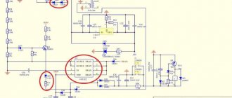
Inverter power supply
Features of devices
When choosing a suitable device for yourself, it is necessary to highlight a number of features that distinguish the manufacturer from other competitors. Unfortunately, it is possible to evaluate the quality and functionality of welding machines only after actual use. That is why marketers try to initially emphasize all the advantages.
- FoxWeld products are not limited to just one device. Production is aimed at fully ensuring the process.
- A developing network of representative offices allows you to receive timely technical support, provide qualified repairs, and also count on warranty service.
- A variety of models in different price categories attracts mass buyers.
- The installations use electronics from American, Japanese and South Korean manufacturers.
- Focus on constant improvement in quality.
Inverter protection and control elements
Several elements in its circuit diagram allow you to avoid the influence of negative factors on the operation of the inverter.
To ensure that transistors that convert direct current into alternating current do not burn out during their operation, special damping (RC) circuits are used. All electrical circuit blocks that operate under heavy load and become very hot are not only provided with forced cooling, but are also connected to temperature sensors that turn off their power if their heating temperature exceeds a critical value.
Radiators and cooling fans take up significant space inside the inverter
Due to the fact that the filter capacitors, after being charged, can produce a high current, which can burn the inverter transistors, the device must be provided with a smooth start. For this purpose, stabilizers are used.
The circuit of any inverter has a PWM controller, which is responsible for controlling all elements of its electrical circuit. From the PWM controller, electrical signals are sent to a field-effect transistor, and from it to an isolation transformer, which simultaneously has two output windings. The PWM controller, through other elements of the electrical circuit, also supplies control signals to the power diodes and power transistors of the inverter unit. In order for the controller to effectively control all elements of the inverter's electrical circuit, it is also necessary to supply electrical signals to it.
To generate such signals, an operational amplifier is used, the input of which is supplied with the output current generated in the inverter. If the values of the latter diverge from the specified parameters, the operational amplifier generates a control signal to the controller. In addition, the operational amplifier receives signals from all protective circuits. This is necessary so that he can disconnect the inverter from the power supply at the moment when a critical situation arises in its electrical circuit.
The user said thank you:
Greetings to all forum participants. We need help in repairing this Dnipro-M SAB-250M device without a power switch. I found a control board diagram on this forum, thanks to forum member Semivosa for the diagram. I finished drawing a little, there may be inaccuracies and errors. The location of the control board is very inconvenient. Maybe it was a waste of time to take and remove the control board from the main one. I would like to try running the control board separately from the main one. After simulating the operation of the power part, connect a light bulb to the TGR winding and solder the minimum control kit. There is a small problem, I don’t know if it will work with a power supply of +12V and -12V, the PC power supply does not have 15V. I forgot to describe the reason for the repair. When connected to the network, the device turns on, the relay is activated, the green LED lights up and that’s all, there is no arc. Upon autopsy it was discovered; The power supply is working +15V, -15V, in stock. Power transistors and output diodes are intact.
You shouldn't do that. You just unsolder the jumper that supplies 310V power, power it through a separate diode bridge with a small mains capacitor, and then you can experiment to your heart’s content. If you unsolder the control board, I don’t recommend turning on the device; the Chinese often skimp on resistors and the gates of the drive transistors hang in the air and can die. You should not use a power supply from a computer, because you cannot control its current; if something is shorted, there will be smoke.
Since you have already soldered the control, then solder the connectors like this into the control and the main board and, as written above, do not experiment with power until you have made the control. Disconnect the output stage and use standard power.
Thank you for not passing by. Applying voltage to the power part without a control board is complete recklessness and a definite murder of power switches. I didn't intend to do this. Of course, you can solder the connector (especially since it’s available), then the board will move 10mm away from the main one and it will be possible to replace parts. Although there is no desire to operate the device with a connector. The slightest loss of contact in the circuit of the primary winding of the TGR and then no one knows what will happen. It’s just that the design of the device itself and the location of the board are very inconvenient. I initially tried without unsoldering the control board from the device, supplied 310V from a separate source, having first soldered the jumper and de-energized the power section. I soldered the power supply and hung a 26V 0.12A light bulb in the place of the TGR winding. I also soldered the output current regulator, brought out two wires, those that go to the current transformer, and the wire that goes to the positive terminal of the output (I still don’t understand the purpose of this pin; it’s either limiting the output voltage or starting the device when it is shorted to the common wire). I applied 15V to 12V. So far the effect has not started and we have these voltages at the UC3846 pins 1)—0.02V, 2)—5.12V, 3)—0V, 4)—0.18V, 5)—minus 0.45V, 6 and 7)—0.68V, 8)—the saw is present with an amplitude of 2V (according to the donkey), 9)—3.67V, 10)—2.5V, 12)—0V (power), 13-15)—power +12, 06, 16)—0.67V. There is no exit from the legs 11.14. I tried it as hard as I could, because I wasn’t afraid to disrupt the generation because the board was lying on the table. Maybe you need to apply some more voltage to start. The low voltage on 1 leg is alarming and should be greater. Dear spices, don’t kick me too hard, I don’t have a radio education, having soldered the board, I want to not only restore the device, but also figure out how it works. Photo taken from this site.
| Special offer for forum participants – discount on Jasik equipment! In order to get a discount, call one of the numbers, (066) 581-35-66 and say the code word: “welding forum”. This only happens once in a lifetime! |
Advantages and disadvantages of inverter-type welding machines
Inverter welding machines, which replaced the usual transformers, have a number of significant advantages.
- Thanks to a completely different approach to the formation and regulation of welding current, the weight of such devices is only 5–12 kg, while welding transformers weigh 18–35 kg.
- Inverters have very high efficiency (about 90%). This is explained by the fact that they spend significantly less excess energy on heating the components. Welding transformers, unlike inverter devices, get very hot.
- Due to such high efficiency, inverters consume 2 times less electrical energy than conventional transformers for welding.
- The high versatility of inverter machines is explained by the ability to regulate the welding current over a wide range with their help. Thanks to this, the same device can be used for welding parts made of different metals, as well as for welding using different technologies.
- Most modern inverter models are equipped with options that minimize the impact of welder errors on the technological process. Such options, in particular, include “Anti-stick” and “Arc Force” (fast ignition).
- Exceptional stability of the voltage supplied to the welding arc is ensured by the automatic elements of the inverter electrical circuit. In this case, automation not only takes into account and smoothes out differences in input voltage, but also corrects even such interference as the attenuation of the welding arc due to strong wind.
- Welding using inverter equipment can be performed with any type of electrode.
- Some models of modern welding inverters have a programming function, which allows you to accurately and quickly configure their modes when performing a certain type of work.
Like any complex technical devices, welding inverters have a number of disadvantages that you also need to be aware of.
- Inverters are highly expensive, 20–50% higher than the cost of conventional welding transformers.
- The most vulnerable and often failing elements of inverter devices are transistors, the cost of which can be up to 60% of the price of the entire device. Accordingly, repairing a welding inverter is quite an expensive undertaking.
- Due to the complexity of their electrical circuitry, inverters are not recommended for use in bad weather conditions and at low temperatures, which seriously limits their scope of application. In order to use such a device in field conditions, it is necessary to prepare a special closed and heated area.
When welding work performed using an inverter, long wires cannot be used, as they induce interference that negatively affects the operation of the device. For this reason, the wires for inverters are made quite short (about 2 meters), which makes welding work somewhat inconvenient.
The user said thank you:
| ✅Special offer✅ – for all AL-KO and STIGA electric garden equipment, a 25-meter extension cord as a GIFT! Call one of the numbers and order a promotional kit, (093) 316-03-61. Don't miss your chance! |
Good evening, today I finally received the missing parts and was able to sit down and re-solder them. This means that I ordered: 2 Ohm resistor - 2 pcs., 12 V Zener diode, PC817C optocoupler. I bought it from a friend who doesn’t know anything about radio components. The store (int.com) mixed up the resistors and gave them 12 ohms. In short, I had to leave the old ones at 2.2 ohms. I re-soldered the optocoupler and zener diode. I serve food to the duty room. Silent. I return the zener diode to 22 V. And lo and behold. The green LED lights up and the relay turns on. I measure the voltage on the relay coil - 25.5 V. As I understand it, you can put back the jumper that you unsoldered on your advice. It might be worth checking something else. You talked about +15 and -15 V. It’s difficult without a circuit; it’s not clear where to measure. It’s not clear how to check the output from the duty room transformer, where the plus is visible from the rectifier diodes. On one there are two in parallel, on the second there is one, but it is not clear what to measure against. I will be glad if you can suggest something else useful.
The issue is closed, the inverter has been repaired. Thanks to Master888 for your help.