17.04.2018
The word “flange” came into Russian from the German language, as did the flange connection itself. In German, the noun Flansch means exactly the same thing as the Russian word “flange” derived from it, ─ a flat metal plate at the end of a pipe with holes for threaded fasteners (bolts or studs with nuts).
Flanges are one of the most common detachable connections used in industry. They serve to connect individual parts of devices. They are also used to connect pipelines, pipeline fittings, sensors and instrumentation to the apparatus, to connect individual sections of pipelines, etc.
The prevalence of flanged connections for pipeline fittings is due to their many inherent advantages. The most obvious of them is the possibility of repeated installation and dismantling.
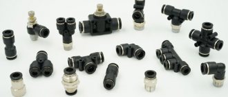
Rice. 1. Flanges
Flange connections are durable and reliable, which allows them to be used to complete pipeline systems operating under high pressure. Subject to certain conditions, flange connections provide very good tightness. To do this, the flanges being joined must have similar connecting dimensions that do not exceed the permissible error. Another condition is mandatory periodic tightening of joints, which allows maintaining the “grip” of bolted joints at the proper level. This is especially important when they are constantly exposed to mechanical vibrations or there are significant fluctuations in ambient temperature and humidity. And the larger the diameter of the pipeline, the more relevant this is, because as it increases, the force on the flanges increases. The tightness of flange connections largely depends on the sealing ability of the gaskets installed between the flanges.
The ability of a flange connection to withstand pressure, temperatures, and, in the case of the use of special materials, aggressive environments, with the possibility of redistributing loads at the joints (steam pipelines, chemical industry plants, etc.) makes this type of connection simply irreplaceable for large pipeline diameters. For small pipeline diameters, flange connections are not justified, since coupling (threaded) connections meet all requirements while being economical.
As a rule, flange connections have a round shape, since it is the most reliable and easiest to implement. However, if necessary, flange connections can be manufactured with a square or rectangular pipe shape.
Rectangular and square flange connections are quite difficult to process and do not always provide the necessary tightness, so they should be used only when absolutely necessary.
General information
There are several types of flange connections, each of which is made strictly in accordance with GOST:
- Flat flanges – GOST 12820-81
- Collar - GOST 12821-81
- Loose flanges on a welded ring - GOST 12822-80
- Flanges for vessels and apparatus GOST 28759.2-90
- Ring plug GOST 12836-80
To ensure a tight connection between parts, seals are used:
Using flanges, not only pipes are connected to each other, but pipes are also installed to other structures. For example, to a container with a flange installed on the nozzle or to join products made of different materials.
Connecting parts are made from:
- Malleable cast iron. The flanges are cast. Permissible pressure 4MPa. Permissible liquid temperature from -300 to +4000
- Become. Cast connecting parts with permissible pressure 20MPa and operating temperature from -2500 to +6000. They are used for installation of products made of different materials.
- Become. Welded flanges. Designed for pipes with low pressure of 2.5 MPa.
- Gray cast iron. Cast flanges are used for pipes with a maximum operating pressure of 16MPa. It is allowed to transport liquids with temperatures from -150 to +3000.
Attention! Steel flanges are cast from alloy, carbon and stainless steel.
Polypropylene flanges are also produced for installation of plastic pipelines with low pressure:
- Pass-through – connecting flanges for pipes
- Blind – designed for installation in dead-end pipeline branches.
In order to connect two parts, you will need two identical flanges that are tightly attached to the end of the pipe.
Flanges are connected in two ways:
- They sit on the thread. This type of installation of the connecting element is applicable only for non-pressure mains.
- Attached by welding.
Flanges intended for one connection are called mating flanges. When the elements are installed, they are connected and secured using bolts or studs. It is easier and faster to fasten the studs, since the threads are on both sides and the nuts can be tightened from both ends at once.
Conditional pass. Features of its designation
It is very important to note that the nominal diameter is not the outer diameter of the pipe, but refers to the passage (section) through which the medium flows through the flange connection. One of the features of steel flat welded flanges and steel free flanges on a welded ring for nominal diameters DN 100, 125 and 150 mm is that three designs are possible for different outer diameters of the pipe.
Therefore, when ordering these flanges for DN 100, 125 or 150 mm, it is necessary to indicate the letter corresponding to the required pipe diameter. If the letter is not indicated in the application (specification) for these flange sizes, then the flanges are manufactured for the following pipe diameters: 100A, 125A, 150B (Table 2).
Tab. 2. Correspondence of nominal diameter DN 100, 125 and 150 to the outer diameter of the pipe.
A feature of flanges with a nominal diameter of DN > 200 mm is that, due to the different accuracy classes of pipes and flanges, boring of the internal diameter of the flat flange, free flange and its ring is allowed according to the actual outer diameter of the pipe with a clearance per side of no more than 2.5 mm, i.e. over the entire internal diameter of the flange and ring no more than 5.0 mm. In other words, when making a pipe, there may be a deviation from the ideal circle shape, so the pipe may not match the internal diameter of the flange, which in turn makes it difficult to connect the pipe and the flange.
Flange connections: types, designs and requirements
Flange connection is a detachable (bolted) method of installing steel pipelines. The flange has a flat body with a large hole in the center and several small ones around the perimeter. The most functional shape of the part is round; rectangular or square ones are less commonly produced. For hermetically sealed fixation, seals are used, the fasteners themselves are carried out with studs and bolts.
Flange connection picture
GOST 33259-2015 regulates flanges with a nominal pressure PN of no more than 250 kgf/cm2. There are 6 structural types of reinforcement.
- Flat weld (01) is a round element that is loosely placed on the pipe and attached to it by welding with two fillet welds. Inner diameter – no more than 2400 mm.
- Butt weld (collar, wellhead) (11) - a flattened ring with a conical neck, the end of which is combined with a pipe butt weld with one seam. DN – up to 4000 mm.
- Valve bodies (cast) (21) are a continuation of the pipe, part of it. The nominal cross-section of the equipment is no more than 2000 mm.
The following three varieties are classified as loose flanges. They consist of a plug that is attached to the pipeline and matches it in material. For the manufacture of the body, more inexpensive alloys are used.
Constructive.
The basis of this group of characteristics is the flange design. In the Russian Federation and CIS countries, three flange standards are most widespread:
- GOST 12820-80 - steel flat welded flange.
- GOST 12821-80 - steel butt welding flange.
- GOST 12822-80 - loose steel flange on a welded ring.
Flanges according to the three most common standards mentioned above are designed to connect pipeline fittings and equipment. Due to their design features, the installation conditions for these flanges vary.
- Flat welded steel flange. During installation, the flange is “slipped” onto the pipe and welded with two welds around the circumference of the pipe.
- Butt welded steel flange. Installation of such a flange, compared to a flat welded flange, requires only one connecting weld (in this case, it is necessary to butt the end of the pipe and the “collar” of the flange), which simplifies the work and reduces time costs.
- Steel loose flange on weld ring
In addition, it is positive that when selecting free flanges for a stainless steel pipe, for the sake of economy, it is allowed to use a stainless steel ring and a carbon flange (Table 1).consists of two parts - a flange and a ring. In this case, naturally, the flange and ring must be of the same nominal diameter and pressure. Such flanges differ from the above in ease of installation, since only the ring is welded to the pipe, and the flange itself remains free, which ensures easy joining of the bolt holes of the free flange with the bolt holes of the flange of the fittings or equipment without turning the pipe. They are often used when installing pipeline fittings and equipment in hard-to-reach places or when frequently repairing (checking) flange connections (for example, in the chemical industry).
| Flange type | Environment Settings | Material grade | |
| Conditional pressure Ru, kg/cm2 | Temperature K (°C) | Flange | |
| Steel flat welded GOST 12820-80 | from 1 to 25 | from -30 to 300 | St3sp not lower than 2nd category according to GOST 535-88 |
| from -70 to 300 | 09G2S according to GOST 19281-89, 10G2 according to GOST 4543-71 | ||
| from -30 to 300 | Steel 20, 25 according to GOST 1050-88 | ||
| from -40 to 300 | 15ХМ according to GOST 4543-71 | ||
| from -40 to 300 | 12Х18H9Т according to GOST 7769-82 | ||
| Steel butt weld GOST 12821-80 | from 1 to 25 | from -30 to 300 | St3sp not lower than 2nd category according to GOST 535-88 |
| from 1 to 100 | from -40 to 425 | Steel 20, 25 according to GOST 1050-88 | |
| from 1 to 200 | from -30 to 450 | ||
| from -40 to 450 | 15ХМ according to GOST 4543-71 | ||
| from -40 to 300 | 5Х18Н12С4ТУ (type) GOST 5632-72 | ||
| from -70 to 300 | |||
| from -70 to 350 | 09G2S according to GOSTG2 according to GOST 4543-71 | ||
| from -40 to 400 | 06ХН28МДТ (type EI-945) according to GOST 5632-72 | ||
| from -70 to 400 | |||
| from -40 to 450 | 12Х18Р9Т 10Х17Н13М3Т (type EI-432) according to GOST 5632-72 | ||
| from -40 to 510 | 15Х5М according to GOST 5632-72 | ||
| from -80 to 600 | 12Х18Н9Т according to GOST 5632-72 | ||
| from -253 to 600 | 10Х17Н13М3Т (type EI-432) according to GOST 5632-72 | ||
| Steel free on a welded ring GOST 12822-80 | from 1 to 25 | from -30 to 300 | St3sp not lower than 2nd category according to GOST 535-88 |
- In addition to these three standards, special mention should be made of flanges manufactured according to customer drawings (non-standard flanges). Unlike the first three flanges mentioned above, this design is not permanent and can be changed depending on the client's expectations and requirements. Such flanges are individual and serve to meet any customer needs.
- Flanges manufactured according to foreign standards differ structurally from Russian ones. Among imported ones, the most widely used in Russia are flanges made according to German DIN standards (a standard accepted throughout Europe) and American ANSI.
| Distinctive characteristics of flanges | |
| Constructive | Technological |
| Nominal diameter DN | |
| Conditional pressure Ru | |
| Version 1 to 9 | |
| Row 1 or 2 | |
| Round (square) | |
| Material | Art. 20 |
| Art. 09G2S | |
| Art. 15X5M | |
| Art. 08Х18Н10Т (12Х18Н10Т) | |
| Other | |
| Design | Steel flat welded flanges GOST 12820-80 |
| Butt welded steel flanges GOST 12821-80 | |
| Steel free on a welded ring GOST 12822-80 | |
| Foreign standard | |
| Non-standard | |
| Flanges according to other Russian standards |
Flanges according to other Russian standards include the following: threaded steel flanges, flanges of vessels and apparatus, insulating flanges for underwater pipelines. They differ from the above in design and applications.
Design features also include (using the example of the three most common GOSTs):
- Conditional pass. It is designated as DN and measured in mm.
- Conditional pressure. It is designated as Ru and measured in kgf/cm2.
- Designs 1 to 9. Determines the type of surface for the gasket.
- Material (represented by Russian steel grades).
What is the part made from?
The industry uses steel flanges, but the steel from which the part is made also varies. The marking of steel flanges will determine in what conditions it is best to use this part:
- Steel 20 is the most commonly used raw material. This is carbon steel, parts made from it are used for assembling fittings on highways, where the external temperature is not lower than –40 degrees, and the internal temperatures are not higher than +475 degrees.
- Steel 09g2s is a steel made of nickel, chromium and molybdenum alloys, intended for welding. Products made from this material can be used at external temperatures from –70 degrees.
- 12Х18Н10Т – cryogenic steel. Parts made from this material can be used in aggressive environments, such as alkalis and acids. Permissible temperature from – 196 degrees to +350 degrees.
- 10Х17Н13М2Т – corrosion-resistant ordinary steel. Fasteners made from it are used in particularly extreme conditions, because it remains resistant to stress corrosion. Operating temperatures from -196 to +600 degrees.
- 15Х5М – low-alloy heat-resistant steel. Such products have high resistance to oxidation at +600-650 degrees.
These brands are the most used, but in addition to them, manufacturers use other raw materials. There are polypropylene models - they are designed for joining polypropylene pipes with metal shut-off valves. The operating temperature of this material is much lower - +80 degrees. They can be supplied with a flange collar - a special part for creating a flange connection made of polypropylene.
Polypropylene flange
In addition to steel and propylene, two types of cast iron are used - malleable and gray. Parts made of malleable cast iron are used at operating temperatures from -30 to +400 degrees, and parts made of gray cast iron are used at temperatures from -15 to +300 degrees.
Production technology
Several methods are used to produce flanges:
- Centrifugal casting
- Stamping or forging
- Cutting from rolled steel sheet using a laser tool.
- Hot forging from blanks in the form of rolling rings.
- Semi-manual method using CNC machines or semi-automatic turning and milling.
The most productive method, often used to produce a serial batch, is stamping, carried out in closed forms - stamps. The least expensive method is to cut parts from sheet steel. The method requires additional ultrasonic testing for the absence of cavities.
During the manufacturing process of parts, regular quality control is carried out. The performance of the lines depends on the quality of the flange; in the event of a failure or accident, the user will incur significant losses. One of the main tests is to check for mechanical integrity and surface evenness.
Currently, a large number of imported equipment adapted to international standards are being purchased. The enterprises have launched the production of “transitional type” flanges, combining the parameters of different standardization systems.
To protect flange connections from exposure to aggressive environments, the flanges are coated with special materials that increase their service life. The surface layer of steel is treated with nickel, chromium, zinc and other materials that prevent premature destruction. The type of coating is determined by the customer.
Characteristic design
A flange is a metal disk of a round or, less commonly, square shape with a perforated plane. A set of fittings of this type includes:
- paired discs;
- bolts and nuts for fastening and tightening these planes;
- gasket made of paronite, fluoroplastic or thermally expanded graphite, ensuring tightness.
Plastic flanges for PVC pipes
Flange disks supplied to the end user in the form in which they came out of the stamping machine can be either smooth or have characteristic notches. This model provides greater tightness necessary for trouble-free operation of water and gas pipelines. The following can be applied to the discs in pairs:
- tenons and grooves;
- projections and corresponding depressions.
Some designs provide recesses for gaskets of various types and shapes. Insulating flange connections of gas pipes require particularly careful quality control of this element.
The dimensions and number of bolt holes are set by the manufacturer in accordance with GOST. The fittings are attached to the pipe itself, as a rule, using a welding machine. Certain types of pipeline flange connections can also be secured using threads applied to the flange disk from the inside. Experts note that in structures of this type, the advantage of the strength of flange connections is practically lost.
Welding flange and steel pipe
Rows
- If the design details of the connecting dimensions (row 1 or 2) are not specified when ordering, then the flange is manufactured by default in accordance with row 2. The structural difference between the flanges of row 1 and the flanges of row 2 is the different number of holes in it for mounting bolts (studs) and their diameters.
- For example, a flange for DN 300 mm and PN 63 kgf/cm2 for row 1 has a mounting hole diameter of 36 mm, and for row 2—39 mm. Similarly, the flange for DN 80 mm and PN 10 kgf/cm2 of row 1 has a mounting hole diameter of 18 mm with a total number of 8 pcs., and row 2, respectively, has 18 mm and 4 pcs. Therefore, this feature must be taken into account when ordering flanges as counter flanges for shut-off valves.
Defects of fasteners
Inspection checks for surface defects, thread condition, and rod bending. If there are dents, nicks, chipping, breakage of more than two threads, bending of rods and noticeable wear, fasteners are rejected. Manual testing determines the suitability of the thread by tightening and unscrewing a bolt or nut.
Sequence of assembly of threaded connections:
- check the joint of the parts being connected for the fit of the mating surfaces;
- if necessary, adjust the joining surfaces;
- align the axes of the holes for fasteners;
- bolts are inserted into the holes or studs are screwed in;
- put on washers and lining locking elements;
- screw on the nuts and pre-screw them;
- measure the gap along the supporting surfaces of the nuts (the fit of the supporting surfaces must be at least 75% along the entire circumference);
- finally tighten the nuts;
- control in accordance with the working drawings the correct mutual orientation of the parts to be connected and the tightness of the joint.
When installing the stud, you must:
- ensure a tight fit in the body;
- set the axis of the stud perpendicular to the surface of the part (non-perpendicularity causes significant stress in the thread).
Depending on the tooling used when assembling threaded connections:
- traditional tightening with torque applied to the nut;
- preheating of bolts;
- application of axial forces to the bolt.
Traditional technology with torque applied to the nut
carried out using wrenches, torque wrenches, torque wrenches, multiplier wrenches, hydraulic, pneumatic, electric impact wrenches. These tools do not have force measurement devices (with the exception of torque wrenches). Traditional technology leads to the occurrence of tangential stresses in the bolt shaft.
The technology for assembling threaded connections with preheating of bolts (up to 100 °C) eliminates the occurrence of tangential stresses, however, it is difficult to take into account heat losses during assembly - this does not allow the creation of specified pre-tightening forces in the bolts.
Technology for assembling threaded connections with the application of axial forces to bolts
eliminates the occurrence of tangential stresses in the rods, and the use of a hydraulic tool makes it possible to control the tightening forces using pressure gauges at the oil station.
Groups of bolts (studs) are tightened with the same force. For non-critical (structural) bolts and studs, tightening is carried out in 2 “rounds”, and for critical (design) bolts - in no less than 3 “rounds” (0.5; 0.7; 1.0 tightening force). Tightening should be carried out in a checkerboard pattern symmetrically relative to the longitudinal axis of the joint.
It is recommended to assemble the connections in two stages. At the first stage, using wrenches, wrenches and special sockets, screw the nut until it stops. At the second stage, using devices, multiplier wrenches, wrenches, hydraulic wrenches or special jacks, the nuts are finally tightened. Threaded connections with pre-stretching are assembled in 2 “passes”.
The assembly of threaded connections of flange joints is carried out in a certain sequence by simultaneously tightening symmetrically located pairs of nuts (pair assembly) or diametrically located nuts (Figure 4.4).
Thread designations:
- M24 – metric diameter 24 mm;
- M24×1.5 – metric diameter 24 mm, pitch 1.5 mm;
- M24LH – metric diameter 24 mm, left, with large pitch.
Screws and nuts are usually made of St3, St4, St5, St35, St45. Bolts for stressed connections are made of St40, 40ХН. The choice of materials and parameters of threaded connections is determined by strength calculations. The bolt designations additionally indicate the length and strength class.
The mechanical properties of bolts, mounting screws and studs made of carbon unalloyed and alloyed steels according to GOST 1759.4-87 (ISO 898/1-78) under normal conditions are characterized by 11 strength classes: 3.6; 4.6; 4.8; 5.6; 5.8; 6.6; 6.8; 8.8; 9.8; 10.9; 12.9. The first number, multiplied by 100, determines the nominal tensile strength in N/mm2, the second number (separated by a dot from the first), multiplied by 10, determines the ratio of the yield strength to the tensile strength in percent. The product of numbers multiplied by 10 determines the nominal yield strength in N/mm2.
Thread diameter
- All threaded fasteners have an internal (nuts) and an external (studs and bolts) thread diameter. Depending on the purpose and the regulatory document according to which the product is manufactured, the thread can be metric or inch. Metric thread pitch is measured in millimeters, and inch thread pitch is measured in inches. Example: M12 - metric thread with a nominal diameter of 12 mm; 3/4" is an inch thread with a nominal diameter of 3/4".
- Example: M12x1.25 bolt - a bolt with a metric thread, a nominal diameter of 12 mm and a fine thread pitch of 1.25 mm.
- Example: for a nut with a nominal thread diameter of 16 mm, a spanner size S of 24 mm is provided.
- Bolt length - the length indicated in the product designation when ordering, in most cases is not a dimensional characteristic. Mostly, the length of the bolt indicated in the product designation is equal to the length of the bolt shank, i.e. the height of the bolt head is not taken into account.
- Example: for a bolt M12x120 - the length of the bolt shaft is 120 mm, while the total overall length is greater by the height of the bolt head by 7.5 mm, i.e. the total overall length is 127.5 mm. In Fig. 3: l - bolt length; l+ k = overall overall length of the bolt.
Stud length
- For most studs, the length l specified when ordering indicates the overall overall length of the stud. However, some regulatory documents do not include the entire length of the stud in the designation of studs.
- Example: GOST 22032-76, which applies to studs with a screw-in end of length dv, provides for the designation of the length of the stud, which does not include the length of the screw-in end. l is the length of the pin, b is the length of the screwed end (Fig. 4).
Version 1
- tolerance field indicates the accuracy of the thread.
- The larger the tolerance field value, the greater the deviation of the thread parameters from the nominal ones.
- For most fasteners, a sufficient thread tolerance zone for external threads is 6d, for internal threads—6H.
- Threaded end length is the length of the part of a bolt or stud designed to screw on a nut.
Types of threaded connections between pipes
Similar to threadless methods, threaded pipe connections can also be detachable or permanent. Although it would seem that any threaded structure can, in principle, be disassembled, there are situations when two pipes connected by a thread are additionally welded to fixed surfaces, which prevents their separation. In this case, they speak of a permanent threaded connection.
However, the above situation is rather an exception; in general, threaded methods are considered as detachable types of pipe connections. There are several varieties, but two have the greatest practical application: bending and bidirectional threading.
Connection by means of a bend is used in cases where the pipes are stationary relative to their own axis, and one of them has a long threaded section, and the other a short one. A locknut and coupling are screwed onto a pipe with a long piece of thread. Next, the coupling is driven from the long thread to the short one until the very end, being pressed on the other side with a lock nut.
Projection height
If you look at the drawing of a steel flange, it has several parameters, including the height of the protrusion. It is designated by the letters H and B; it can be measured in all types of products, except those that have an overlap connection. The following should be remembered:
- models with pressure class 150 and 300 will have a projection height of 1.6 mm;
- Models with pressure class 400, 600,900,1500 and 2000 have a projection height of 6.4 mm.
With a projection and a recess In the first case, suppliers and manufacturers of parts take into account the surface of the projection, in the second case the surface of the projection is not included in the specified parameter. In parts brochures, these figures may be indicated in inches, where 1.6 mm is 1/16 inch, and 6.4 mm is ¼ inch.
Manufacturing materials and types
To connect metal pipes, flanges made of the following materials can be used:
- Gray cast iron. Parts are made by casting. The use of these parts is permitted at operating pressures up to 16 MPa. The temperature of the transported medium must be in the range from -15 to +300.
- Cast iron is malleable. Parts are manufactured by casting. It is allowed to be used for installation of pipelines with a working pressure of up to 4 MPa, but the operating temperature range is wider - from -30 to +400.
- Steel. Cast steel flanges can be used to connect pipes made of different materials. The maximum operating pressure is up to 20 MPa, the temperature range is very wide - from -250 to +600 degrees.
- Steel. Welded flanges are used for assembling pipelines operating at low pressure - up to 2.5 MPa.
Advice! For the manufacture of flanges, different types of steel are used - alloy, carbon, stainless.
Relatively recently, flanges made of polymer material began to be used. Polypropylene parts are used on plastic pipelines operating without pressure (or with low pressure). Depending on the purpose, there are two types of flanges:
- Walkthroughs. They are used to connect the pipe to other parts of the pipeline.
- Deaf. Installed in dead-end branches of the highway.
Gasket selection
Gaskets must be used to seal the connection. It is especially important to correctly calculate the degree of sealing when operating a pipeline under pressure. The choice of material for the manufacture of gaskets depends on the operating conditions and the properties of the transported medium. Most often used:
- Rubber. Depending on the properties of the environment, a material is selected that is resistant to acids and alkalis, oil and petroleum products, and temperature.
- Paronitis. General purpose or oil resistant material can be used.
- Fluoroplastic.
- Asbestos cardboard.
The gasket is cut to the shape of the flange; its thickness depends on the selected material.
Tightening process and sequence of actions
Once the flanges are welded and the gasket is installed between them, you should make sure that it does not interfere with the installation of tie bolts or studs.
To ensure uniform tightening of the pipes, all bolts are tightened to a slight force. Then the first bolt is tightened, and the second after it will be the opposite one, etc. The tightening method is called “crosswise” - this will ensure maximum uniformity of the gasket seal and prevent excessive stress on the pipes.
Application areas for connection parts
Speaking about such an element, it is necessary to make it clear that it is not a part for fastening. The main task of this device is to create a supporting structure for the fastening bolts and at the same time to ensure the tightness of the connection.
As a locking or connecting part, they are installed in communication networks of housing and communal services, in the oil production industry. They are also widely installed in the fuel and gas sectors. In these industries, very durable and long-lasting flange mountings are used for network installation of measuring instruments.
Different technological manufacturing features and types of materials for these elements make it possible to effectively operate networks that carry aggressive substances under high pressure.
When laying a system of steel pipes, discs made of a similar material are most often used. This creates the same level of load pressure and serves as a safety net against damage to component parts after exposure to temperature surges.
Such damage is typical for seams on materials characterized by unequal heat conductivity. Cast iron, aluminum, brass and bronze flanges are installed on steel pipes. But, the undisputed leader among the options for such work is their carbon steel products. There are several reasons for this:
- Not a big cost.
- Practicality.
- Easy to process.
Flange connections can be found in any field. A wide variety of materials for the production of these devices makes it possible to effectively use any highway.
Some types of systems provide a special recess for gaskets. Flange fastenings in the network transporting gas require especially careful monitoring. Here you will need flanges that have undergone detailed quality testing.
Preparing flanges for installation
Before you begin assembling the flange connection, you must check them for rust and mechanical damage. Surfaces are cleaned and degreased. Remove burrs from the threaded part of the bolts and nuts. Pre-run the threads by screwing the nuts onto the bolts and then lubricating them. Cut and try on the gasket. It should be centered without blocking the mounting holes. Reusing old gaskets is undesirable, but if there is no other choice, install several used ones.
What is a flange and what types are there?
In most cases, flanges are ring-shaped plates of steel, but sometimes they are made in the form of a square or rectangle. The end of the pipe is inserted into the central large hole, and bolts or studs are inserted into the holes evenly distributed along the outer perimeter. The list of flange types includes feedthroughs and plugs. The first are intended for joining pipeline elements, the second close dead ends or cut off sections being repaired or replaced.
To ensure that products made in different countries are interchangeable, a unified classification of flanges has been developed. In Russia this is GOST, European countries use the German DIN standard, and America, Japan and Australia use ANSI/ASME. However, often the same flanges are indicated by different symbols. Therefore, standards are translated using special tables.
The performance standards are indicated in GOST 12815-80 in numbers from 1 to 9:
- With a connecting protrusion in the form of a chamfer at an angle of 45⁰.
- Same as 1, but the protrusion is at a right angle.
- With a groove on the inside and a projection at an angle of 45⁰ on the outside.
- With a spike.
- With internal annular groove.
- With a chamfer for the lens gasket (vibration insert) on the inside.
- Sample for oval gasket.
- With spike for fluoroplastic gasket.
- Same as 8, but instead of a tenon there is a groove.
Types of flanges
When installing pipelines, several types of flanges are used:
- The collar ones are designed for a pressure of 0.1 - 20 MPa at a temperature of -200 - +600⁰ The protrusion in the central part (collar) is butt welded to the pipe with one seam.
- Flat ones hold pressure up to 2.5 MPa at temperatures -70 - +300⁰. They are put on the ends and secured with two welds.
- Hardware for connecting equipment or devices;
- Threaded versions are screwed onto the ends.
- Freely rotating ones consist of a plate and a ring, which is welded to the end, and the flange rotates freely on it. This flange connection is installed in hard-to-reach places or where frequent preventive measures are required on the pipeline. Designed for pressure up to 2.5 MPa.
- Ring options for plugs are made without a central hole.
Current quality standards
To standardize products, there are several classifications that work throughout the world.
- GOST – quality standard in force in the CIS countries;
- DIN – European standard;
- ASME/ANSI is a standard valid in Japan, the USA and Australia.
According to the classifications given, tables with translations for the specified values have been created.
Working temperature
- One of the most important parameters is the operating temperature. Based on the temperature of the medium that will be transported through the pipeline, as well as taking into account the external environment, the grade of steel from which the fasteners will be made depends. Each grade of steel has a certain range of operating temperatures at which the fastener can provide strength and reliability of the connection.
- For example, at the same nominal pressure at a temperature not lower than -30 °C, it is recommended to use studs made of steel 35, while at an expected operating temperature of up to -70 °C, fasteners made from cold-resistant steel grades, for example, 09G2S, should be used or 10G2.
Wafer connection
Wafer connection is a fairly common type of connection for pipeline fittings. Wafer valves do not have their own flanges or threads; they are installed between two flanges and tightened with studs.
The advantage of wafer connections
- Wide use. The wafer connection is suitable for most process components and operating environments.
- Reducing the construction length of the product, as well as reducing its weight, as a result - a small load on the pipeline, and a lower price.
- Facilitation of installation in limited conditions, the ability to rotate the valve to the desired position around the axis of the pipeline.
- The ability to easily dismantle the required system unit for repair and cleaning.
- Possibility of installation in flammable and explosive areas, due to the absence of the need for welding.
(symmetrical wafer disc valve, control - handle)
Difficulties when installing a wafer valve lie in correct centering, i.e. the location of the valve and flanges relative to each other, as well as the uniform tightening of the tie rods. If the studs are unevenly tightened in the wafer connection, leaks may occur, as well as deformation of the valve body.
Assembling and disassembling bolted connections
1.1. Preparing for assembly
The assembly of a bolted connection begins with the preparation of the surfaces on which the parts are connected. To create a tightness, sometimes the planes are scraped or ground. It should be noted that the tightness of the joint increases 2-2.5 times when reassembling the joint. The size of the gap between the connector planes must be indicated in the drawings. Forged or cast parts must have machined surfaces for the fasteners to be installed.
1.2. Assembling bolted connections
The most common type of bolted connection is a connection assembled with bolts or screws. When preparing a connection for assembly, it is necessary to check that in the assembled connection of fasteners with metric threads (Table 1), there is a supply of threads, drilling depth and exit of the end of the screw from the nut with metric threads in accordance with Table. 1.
Table 1. Thread margin, drilling depth and screw end exit from a nut with metric threads, mm, for fasteners with metric threads (empirical values)
| Thread pitch P | d thread | ≥ a1 | ≥ a2 (without run) | ≥ a3 | a4 | With |
| 1,0 | 6 | 3,5 | 2 | 6 | 1,5÷2,5 | 1,0 |
| 1,25 | 8 | 4 | 2,5 | 8 | 1,5÷2,5 | 1,6 |
| 1,5 | 10 | 4,5 | 3 | 9 | 2÷3 | |
| 1,75 | 12 | 5,5 | 3,5 | 11 | 2÷3,5 | |
| 2,0 | 16 | 6 | 4 | 12 | 2,5÷4 | 2 |
| 2,5 | 18, 20, 22 | 7 | 5 | 15 | 2,5÷5 | 2,5 |
| 3,0 | 24, 27 | 8 | 6 | 18 | 3÷6 | |
| 3,5 | 30, 32 | 10 | 7 | 21 | 3,5÷7 | |
| 4,0 | 36, 39 | 12 | 8 | 24 | 4÷8 | 3 |
| 4,5 | 42, 45 | 12 | 9 | 27 | 4,5÷9 | 4 |
| 5,0 | 48, 52 | 15 | 10 | 30 | 5÷10 | 5 |
| Depth of screwing, a = Kpd | ||||||
| σВ, MPa | Steel, bro |
Technological.
These characteristics are related to the characteristics of production (from what blanks and by what technologies the flange is made).
Round and square flanges. Currently, a small number of gate valves, valves, etc. are produced for pipeline fittings that have a square flange as a connecting unit. Therefore, in accordance with GOST 12815-80, up to a nominal pressure of 4 MPa (40 kgf/cm2), both round and square flanges are provided by design. When ordering square flanges, it is necessary to remember that there is a direct dependence of the flange diameter on the nominal pressure: the higher the pressure, the smaller the diameter of the flange can be produced (Table 2).
| Ru, kg/cm2 | 1,0; 2,5; 6,0 | 10,0; 16,0 | 25,0; 40,0 |
| Du, mm | 10, 15, 20, 25, 32, 40, 50, 65, 80, 100 | 10, 15, 20, 25, 32, 40, 50, 65, 80 | 10, 15, 20, 25, 32, 40, 50 |