[Forging pneumatic hammer] is used for processing metal products by chopping, broaching, bending, and knocking out various holes.
Its use makes it possible to perform stamping using backing dies; working with closed dies is not recommended, since hard blows from a forging hammer may cause the headstock to be repaired.
The peculiarities of the functioning of a pneumatic forging hammer consist in the use of air, which enters the compressor of the equipment from the environment.
The incoming air, during the reciprocating action of the compressor piston, is compressed and then discharged.
The piston is driven by a drive-type electric motor using V-belts.
The working chain device also includes: a gearbox, which helps reduce the level of rotation of the crank, a crank shaft and a connecting rod.
If you pay attention to the presented drawings, you can see that the forging pneumatic hammer may not have a gearbox in the operating circuit.
In this case, the connecting rod and the crank shaft are connected, and the shaft is equipped with a flywheel.
A pneumatic forging installation differs from a steam-air forging equipment, in which the functioning of the falling elements is supported by steam or compressed air.
A pneumatic hammer is a device in which air serves as an elastic air cushion.
Thanks to it, the movement from the compressor piston to the worker is not transmitted rigidly.
The number of blows that a forging pneumatic hammer can perform in 60 seconds corresponds to the number of revolutions made by the crank shaft.
The forging pneumatic hammer can be equipped with falling elements with different weights, from 50 to 1000 kg. In this case, the shock wave can range from 0.8 to 28 kJ, speed from 5 to 7.5 m/s, multiplicity - 12%.
The operation of the compressor piston is carried out by a stroke with one degree of freedom, which is determined by the position of the angle of rotation of the crank shaft.
Video:
The working piston is installed in the lower position, the compressor piston is in the upper position, and the firing pin is located on the forging.
IMPORTANT TO KNOW: Using 3D milling and engraving machines for metal
Thus, both cavities of the compressor cylinder are combined with the atmosphere with an initial pressure corresponding to atmospheric pressure.
A similar pressure is also established for the cavities of the working cylinder of a forging hammer, since they communicate through taps with the cavities of the compressor cylinder.
If you have a lot of experience and the necessary materials, then making a pneumatic forging hammer with your own hands will not be difficult.
Having such blacksmithing equipment available, you can decorate your own home in an original way or start a profitable business.
How to assemble a pneumatic forging device, the instructions from the video material will tell you about this in more detail.
But to assemble a simple blacksmith’s hammer, you don’t need much experience. Homemade equipment can operate using a foot or electric drive.
In the latter case, the drive is connected to the electric motor using gears.
Classification and types
Depending on the type of energy carrier used, the following types of units described are distinguished:
- Steam-air hammer, which uses the energy of superheated steam.
- A pneumatic hammer whose energy source is compressed air.
- A hydraulic hammer that deforms the workpiece by the force of the flow of a working liquid medium (water or oil).
- A hydraulic screw hammer, where, along with fluid energy, mechanical energy is also used.
- A mechanical hammer for which the principle of direct conversion of potential energy/work into kinetic energy is implemented.
Hydraulic Hammer Steam Air Hammer
Air hammer
Classification is also carried out according to technological purpose; this determines the design features of the hammers. In particular, a forging hammer has free-standing racks, and a steam-air hammer is distinguished by the design of racks connected to the hammer using fasteners, spring-loaded parts.
The layout principle of all hammers is mainly vertical. The few variants of horizontal hammerless hammers - impactors - have not gained much popularity. The reason is the difficulty of holding a heated workpiece during pressure treatment. At the same time, shaking of the ground and foundation is significantly reduced, which makes working with such equipment more comfortable.
Hand forging tool
Hand forging is mainly used for repair and assembly work, as well as for the production of unique, including artistic products in small quantities.
In this regard, hand forging is currently undergoing intensive development. Depending on the type of forging, blacksmith tools are divided into tools for hand and machine forging. According to their functional purpose, all forging tools are classified into basic technological ones; supporting and control. Depending on the nature of use, the tool can be universal or specialized.
The main technological tool is a tool that directly deforms the metal and gives it the shapes and dimensions specified in the forging drawing. In turn, the main technological tool for hand forging is divided according to purpose into support, impact and backing.
1.1. The main technological tool for hand forging
Manual forging operations, such as broaching, upsetting, bending, punching and piercing holes, cutting, forge welding and straightening, are performed using a support tool, which includes anvils (Fig. 1). They are made by casting from steel grade 45L weighing 70...350 kg. The top flat part of the incus is called the face. Sometimes a steel plate up to 30...40 mm thick is welded onto the top of the face, which is called the platband. After heat treatment, the hardness of the face or casing should be 40...45 HRC.
Based on the number of conical parts called horns, three types of anvils are distinguished: hornless (GOST 11396–75), one-horned (GOST 11397–75) and two-horned (GOST 11398–75). Anvil horns are used, for example, when performing bending and forging operations of hollow forgings. On the flat part of the anvils, two through holes are usually made: a round one for punching holes in workpieces and a square one for installing a backing tool.
Rice. 1. Anvils: a – hornless; b – one-horned; c – two-horned
The lower part of the anvil - the shoe - has four legs, with which the anvil is attached to the chair using crutches or clamps. The latter is a concrete pedestal or wooden block dug into the ground to a depth of 1...1.5 m. In this case, the front surface of the anvil should be at a distance of 750...800 mm above the floor level.
Shperak (GOST 11400–75) is a small anvil (Fig. 2) with two horns weighing up to 50 kg. It is made by casting or forging from steel 45. Its casing has a hardness of 40...45 HRC. The shperak is installed in the square hole of the anvil.
Rice. 2. Shperak
Impact tools for hand forging are sledgehammers and hammers. The latter are sometimes called handbrake. A blacksmith uses a hammer both to strike and to indicate to the hammerman where to strike with a sledgehammer when processing relatively large workpieces. Hammers are made with a mass of 0.5...2 kg by forging from U7 or U8 steel.
The hammer contains two strikers, one of which is round or square, sometimes octagonal, and has a smooth striking surface with rolled edges. The other firing pin, also called the butt or toe, can be spherical, pointed with a rounded edge, or blunt. The hammer heads are hardened and then tempered.
Sledgehammers are the main tool for hand forging. They are used to strike a workpiece heated to forging temperatures; they also have two strikers and are divided into blunt (GOST 11401–75) and pointed (GOST 11402–75) (Fig. 3). The mass of the sledgehammers is 2…16 kg. Pointed sledgehammers can have transverse or longitudinal toes (backs).
To secure the handle in the sledgehammer, an oval attachment hole is provided, which expands from the middle to the edges. Sledgehammers are made by forging or stamping from steels 40, 45, 50 and U7, followed by cutting of the working surfaces.
Rice. 3. Sledgehammers: a – blunt-nosed; b and c – pointed-nosed with transverse and longitudinal hindquarters, respectively
After heat treatment of the sledgehammers, the hardness of the working layer up to 30 mm deep should be 48...52 HRC.
Forging chisels (GOST 11418–75) are made from steel U7 and 6ХС and are used for hot and cold chopping of metal (Fig. 4). The former are sharpened to an angle ≥ 60°, the latter – to an angle ≤ 50°. The blade of chisels is made straight, semicircular or shaped. Its hardness at a length of ~30 mm from the working edge is 50...56 HRC, and the hardness along the impacted part at a length of ~20 mm is 30...40 HRC.
Smoothers (Fig. 5 and 6) are used to smooth out unevenness and final finishing
Rice. 5. Ironer
Rice. 4. Forging chisels for cold (a) and hot (b) cutting
Rice. 6. Smoothers (upper and lower) for forging a cross-shaped blank (late 19th century)
both flat and shaped surfaces of forgings; made by forging or stamping from steel U7, steels 40 and 45, followed by cutting. Weight 1…5 kg.
Punchers , or beards (Fig. 7), are used for punching round, square, rectangular and other holes; They are produced by forging from steel U7, steels 40 and 45. The hardness of the working part is 40...45 HRC. Weight 0.7…2.0 kg.
The undercuts (Fig. are made according to GOST 11420–75 from U7 steel. They are backing chisels and are inserted with a square shank into the same hole in the anvil. The undercuts significantly speed up and facilitate the cutting process. The undercut blade can be straight or shaped. It is hardened to a hardness of 48... 52 HRC.
Crimpers (Fig. 9) are used for rolling and finishing the side and other surfaces of forgings. They consist of two parts: the lower part (bottom), inserted with a shank into the anvil, and the upper part (top), mounted on the handle. The swaging is produced by forging from steel U7, steels 40, 45, 50, 40X, processed by cutting and subjected to hardening and tempering to a hardness of 48...52 HRC on the working part and 30...40 HRC on the impacted part. The weight of the crimps ranges from 3 to 25...35 kg.
Rice. 7. Punchers
Rice. 8. Sweeping
Rice. 9. Upper (a) and lower (b) crimps
Rice. 10. Semicircular tampers: a – bottom; b – upper
Rice. 11. Nailers: a – simple; b – special
Tampers (Fig. 10) are used for broaching, making grooves, concave surfaces, as well as for finishing some sections or the entire surface of the forging. The shape of the working areas of the tamps is determined by their purpose and can be very diverse: flat, crescent-shaped, etc. Tampers are made by forging from steel U7, steels 50G, 40X with a hardness of the working parts of 40...45 HRC.
Nailers (Fig. 11) are metal plates made by forging from steel 45 or U7. They have holes for landing the heads of bolts, rivets, nails, etc.
Rice. 12. Forge mold
Forging mold (Fig. 12) is a cast plate made of steel 35L or 40L weighing up to 50 kg with through holes and shaped cutouts on the side surfaces. Designed for finishing forgings, punching holes and profile bending work.
Instructions for assembling a blacksmith hammer
Two vertical posts are welded to the frame of the bed; their height depends on the required hammer impact force.
Then an axle is attached to the posts for the lever structure, which can be welded or fixed in the holes made.
It is better to use the second mounting option so that if necessary, repair the lever; it can be easily disassembled.
After the hammer is assembled, it is recommended to check the horizontal installation, since even minimal distortions should not be allowed.
The anvil for a forging hammer can also be made from strip steel.
Video:
First, a frame is made using welding from a corner of a suitable size, and it is welded to the front of the frame. Then the workpieces are laid on it and welded.
A thick metal sheet is laid and welded on top along the perimeter of the frame. In this case, the surface of the anvil must have a strictly horizontal position.
The article ends with useful video material on the topic of how to properly maintain and repair forging equipment.
Construction of a frame structure for a forging hammer
A channel is used to make the frame. Typically, its parameters are selected based on which products will be processed. As a rule, a 12x8 cm channel is suitable for household equipment.
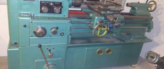
IMPORTANT TO KNOW: Choosing a tabletop metal lathe
The distance at which the channel sections will be located from each other is selected taking into account the size of the anvil - it can be 80-100 cm.
Either the same channel or an iron pipe are used as metal spacers.
In this case, the spacer in the front part of the frame - the future location of the anvil - must be mounted under the channel.
Since it is the front part of the forging installation that will be subject to heavy loads during the working process.
The rear spacer of the installation should be welded near the top level of the channels.
Selected hammer models
The designs of modern forging machines are not copies of the previously listed types, and in terms of operating principles they are very different from classical designs. Hydraulic hammers often now have pneumatic elements, and pneumatic hammers often have hydraulic components. Purely mechanical hammers are gradually becoming a thing of the past in industrial production. Manufacturers configure their products for reasons of energy savings, ease of use and, of course, increased productivity.
Let's look at individual models of modern forging machines supplied to the Russian market by both domestic and foreign companies.
Model MA-4127
The pneumatic hammer MA-4127, which has a mass of the falling part of 50 kg, can easily be called indispensable in artistic forging. This machine is manufactured by PromStroyMash, a company specializing in metal cutting and forging machines. The purpose of the MA-4127 is such work in the forge shop as hot cutting of steel blanks, bending and broaching, and punching holes in them.
The hammer has a solid cast iron frame, made by shaped casting, on which all its main components and mechanisms are mounted. This layout of the machine successfully allows it to carry out all the required technological and energy functions. The control of the hammer is of a combined type - manual with the help of a handle and pedal for actions with the foot. This expands the technological capabilities of the machine and is convenient for the blacksmith.
The stroke of the hammer is 300 mm, and the diameter of the compressor cylinder is 225 mm. The machine receives energy for operation from a 4 kW electric motor, and the optimal side size of a steel square for forging is 50 mm.
You can buy MA 4127 now from the manufacturer for 490 thousand rubles.
Model MA-4129
The hammer MA-4129 differs from the previous model in that it has a larger weight of the falling part, equal to 80 kg. This machine is not recommended for the use of closed dies, as it has a high rigidity of the impact mechanism, which can lead to failure of the bearing or axle box.
The air compressed by the compressor sets the machine head in motion. The mechanical drive electric motor, which has a squirrel-cage rotor, serves as the source of energy for the working cylinder of the machine. Structurally, the drive is designed as a crank mechanism with a V-belt drive. If it is not possible to supply electricity to the machine, it can be powered from the tractor transmission.
The hammer hammer MA-4129 is empty from the inside, in the upper part of which there is a piston ring. From below, this hollow part ends with a solid rod.
The hammer has several operating modes: idling, holding the woman suspended; blows on the workpiece in automatic mode; single controlled impacts; pressing down the workpiece.
The price of the MA-4129 forging hammer from the manufacturer is now 541 thousand rubles.
Model BlackSmith
The BlackSmith KM1-16R pneumatic forging hammer is used in a wide variety of parts manufacturing applications. It is almost an ideal forging machine design for a small profile forging workshop.
This mini forging hammer has frequent strikes and is light in weight and has a low price. The machine is very reliable and easy to operate. The machine is good both for a person’s first steps in the forging craft, and for those cases when high productivity is required in the work of a blacksmith.
The BlackSmith KM1-16R is characterized by the following operating parameters:
- MPCh – 16 kg;
- machine productivity - 258 beats/min;
- impact energy – 180 kgC;
- the size of the woman's fall stroke is 180 mm.
The most suitable dimensions of the part to be forged are 20 mm for the side of a square or the diameter of a round piece. The cost of this forging machine is 120 thousand rubles.
How to install hammer MA4132
Preparing for initial launch
The hammer is connected to the electrical network, checking the grounding and compliance of the network voltage with the electrical equipment of the hammer. Before turning on the hammer, be sure to manually turn the crank shaft by the drive pulley to make sure it rotates freely.
After this, you must: a) Check the presence of a ball valve in the buffer device of the working cylinder. The absence of a ball or poor condition of the valve can cause the woman to hit the lid. b) Check the reliability of the wedge fastening of the upper and lower strikers, the fastening of the cushion to the striker, the reliability of the connection of the lower head of the connecting rod with the connecting rod. c) Pour oil into the working and compressor cylinders and into the pump reservoir. If there is no oil in the oil level indicator of the pump reservoir, the hammer cannot operate. d) Follow the instructions from the hammer data sheet, set out in the sections “Electrical equipment” and “Lubrication system” related to start-up. e) Familiarize yourself with the purpose of the control handles according to the air distribution diagram (Fig. Air distribution diagram) and check their operation when the hammer is turned off. f) Run the hammer at idle speed for 15-20 minutes, test all operating modes, check the flow of lubricant into the cylinders. g) Perform test forging of a heated billet with a height of at least 45-55 mm. Start working in the automatic cycle with light, smooth strokes.
Adjustment During operation, it becomes necessary to adjust individual components of the hammer to restore their normal operation. Therefore, it is necessary to carefully monitor the heating temperature of the working and compressor cylinders, which should not exceed 9°C. At least once every six months, it is necessary to check the condition of the piston rings - their joints should not be located opposite the holes in the cylinders.
The tightness of the connecting rod stud nuts on the lower head of the connecting rod should be checked periodically. In addition, it is necessary to ensure that the dimensions of the upper and lower strikers are the same and their edges match.
Considering that air leaks impair the performance of the hammer and reduce the operating coefficient, it is necessary to periodically check the condition of the cylinder covers, the O-rings of the wheel axlebox and the compressor axlebox, as well as the entire air distribution system, promptly eliminating any malfunctions and replacing worn parts with new ones. Systematic adjustment of the tension of the V-belt drive belts is also necessary (especially carefully monitor their tension in the first 48 hours of hammer operation).
The belt tension is controlled by the force Q required to pull the belt branch by a deflection amount equal to 1.55 mm for every 100 mm of the center-to-center distance. For a new belt, Q is 4.6 kg, for a run-in belt - 3.7 kg.
The belt deflection for a certain center-to-center distance should be: L – belt deflection in mm; A – center-to-center distance in mm. Belt tension can also be monitored with a spring dynamometer. If one of the belts fails, the entire set is removed, since it is unacceptable to assemble new belts with used ones.
Instructions for maintenance, operation and repair (instructional and technological map of shift maintenance)
Before starting the shift, conduct an external inspection and check:
- Cleanliness and serviceability of the equipment, absence of foreign objects on moving parts (visually).
- Presence and serviceability of guards on rotating and moving parts (visually).
- Reliability of fastening of components and parts, serviceability of belt drives (visually).
- Availability and serviceability of grounding devices (visually).
Check the presence of lubricant and, where possible, it should be supplied:
- Clean and fill grease fittings contaminated with lubricant, replenish containers and devices with liquid or grease, manually lubricate exposed rubbing surfaces (according to the operating manual and lubrication card).
- Check the oil level in crankcases and containers of centralized lubrication systems (according to the operating manual and lubrication chart).
- Bleed the centralized lubrication systems, check the supply of lubricant to all points accessible for inspection (according to the operating manual and lubrication chart).
Start at idle speed, while checking:
- No extraneous noise (auditory).
- No unacceptable heating at the joints of moving parts (to the touch).
- Operation of the lubrication system (according to the operating manual and lubrication chart)
- No oil leaks (according to the operating manual and lubrication chart).
Make an entry in the operational log indicating the date, position, name and signature. All detected defects must be corrected. At the same time, turn off the power to the hammer.
Design and principle of operation
The functioning of a forging hammer is based on the dynamic impacts of the working body - the rod, connected to the head (the striking part of the machine) and devices that control the force of impact. Other required structural elements are:
- a piston connected to a woman;
- base (fixed on a solid surface);
- bed (guides for moving units are fixed on it);
- drive equipment;
- shield fence (for operator safety);
- electrical equipment;
- compressor cylinder (for pneumatic hammers).
Early machines were either foot or hand driven. A modern forging hammer is equipped with a convenient control system that minimizes the effort of the forge worker.
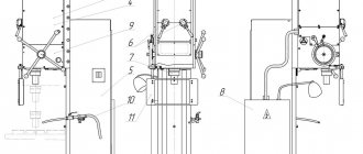
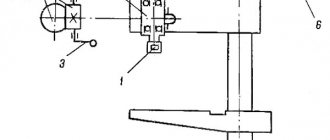
Rice. 1. Pneumatic hammer device.
(1 - working cylinder, 2 - compressor cylinder, 3 - piston, 4 - crank mechanism, 5 - woman, 6 and 7 - upper and lower strikers, 8 - cushion, 9 - air distribution mechanism, 10 - deformable workpiece)
Briefly, the device works like this:
- the workpiece is placed in the lower part of the hammer (usually the hammer);
- set the device to a certain impact frequency and set it in motion;
- after activating the hammer, the driven upper part hits the workpiece;
- the dynamic effect continues until the workpiece acquires the desired shape.
We make a pneumatic hammer
The capabilities of this equipment will be determined by the design of the compressor, which will supply the air distribution mechanism with energy.
In this case, a set of drawings should be developed regarding the following components:
- bed (it is better to design a forging hammer with your own hands with a welded bed);
- a working cylinder selected according to the desired impact energy;
- rod;
- pipelines;
- control systems;
- Shabota.
On the Internet you can find suitable drawings of an electric pneumatic hammer. drive. If they are not there, then design is carried out in the following sequence:
We select a compressor: the compressed air consumption should be approximately 5...6 times greater than the volume of the working cylinder. This, in turn, depends on the required pressure on the metal. For example, for steel it must be at least 30 MPa, therefore, the minimum diameter of the rod is 120...150 mm, with a stroke of 150...200 mm (a further increase in the stroke, of course, will increase the kinetic energy, but at the same time it will also cause a significant increase in the height of the equipment). Therefore, the compressed air pressure must be at least 6 at; it will increase if the compressor is located at a distance from the forging unit, since in this case there will be losses of compressed air in the pipelines.
DIY mechanical hammer
You can make a homemade hammer for forging in several stages:
- Preparing the foundation for installation.
- Creating a machine frame.
- Assembly of the mechanism.
- Installation of the device.
But before you begin manufacturing the entire structure, you need to decide on the dimensions of such equipment, which will subsequently determine its weight and capabilities. Examples of devices are shown in the diagram.
The easiest way to make a forging mechanical hammer, shown in option “A” with a horizontal arrangement, it will be more stable.
Foundation
Having made a drawing of the future device, they begin to prepare the foundation. It is needed for normal operation to prevent the hammer from tipping over and dampening the impact force.
A hole of the required size is dug at the installation site. Sand and crushed stone are poured into the bottom, watered and compacted. A reinforcing frame made of 12-14 mm reinforcement is mounted on top, always with bandaging in increments of 250-300 mm.
Concrete is prepared in a ratio of 1:2:3 (cement grade M400, crushed stone fraction 10-20, and sand).
Filling should be done at a time, constantly trying to compact the mass to avoid voids inside.
Upon completion, anchor bolts can be installed in the uncured concrete, onto which the installation will then be additionally attached.
The frame material is selected depending on the installation parameters and dimensions of the parts being processed. Either a profile pipe or a channel will do. You can also use other convenient rolled metal.
The frame is assembled by welding. Additional spacers and cross beams must be installed.
Mechanism
The main working part - the lever with the striker and counterweight - can be monolithic or prefabricated. The metal must be solid (not a pipe), otherwise the rod will gradually deform under the weight. Such a lever can be “collected” from strips by welding them together.
The firing pin must be made of tool grade steel and, preferably, hardened for greater strength. It needs to be welded to the lever.
Any heavy metal or other material will be suitable for a counterweight.
It is also better to make the shaft on which the hammer will rotate from a solid piece of steel. The lever itself with the hammer is fixed on the axis using transverse pins. The shaft in the frame must rotate freely, so it is best to equip the ends with appropriate bearings.
The drive pedal and transmission can be welded from a regular profile pipe to the required size. Moreover, the control lever itself must move freely. Bearings or simply pieces of pipe into which the shaft with the pedal are mounted are also suitable for this.
Hammer assembly steps
Initially, you need to assemble and install the frame of the device on the foundation. The lower slide is mounted on anchor bolts with nuts. The remaining guides and jumpers are welded to them.
A shaft is inserted into the racks, onto which a lever with a hammer is fixed.
The assembly of the drive with a pedal or lever is also carried out.
The anvil itself can be made from a piece of rail, I-beam or channel. However, it is desirable that the front part be hardened.
After final assembly and testing, the structure must be painted.
What can you add to this material from your personal experience in making such devices for forging metal? What designs have you used? Share your ideas in the comments section of this article.
In blacksmithing, a master cannot do without a number of special tools, including a blacksmith’s hammer. Such a unit is capable of deforming a metal workpiece, giving it a certain shape.
Features of the operation of such equipment in practice are determined by its type, capabilities and structural features.
Homemade hammer: super hammer
It will be easier to make a homemade blacksmith hammer for forging metal products if you divide all operations into several stages in the following sequence:
- preparing the base for installation of a forging hammer;
- designing a machine frame with springs;
- assembly of the working mechanism;
- installation of a homemade device.
Important! The design of a forging hammer largely depends on its type. It is possible to make a mechanical version at home, but constructing an electric or hydraulic hammer yourself is extremely problematic.
But before detailed instructions indicating how to make a blacksmith hammer, it should be noted the importance of creating a drawing of the future design.
Blueprints
You can make a forging hammer with your own hands in a workshop or garage. But before work, it is important to determine the current dimensions of the unit, describe all its component parts, which will subsequently make it possible to determine the weight of the product and its functionality.
To do this, you will need to draw up yourself or find on the Internet drawings and an assembly diagram of such a structure with a detailed description of all its parts.
On a note! It is easier to make mechanical-type forging hammers with your own hands, based on the classification of such units according to the nature of the force used.
Foundation
After creating the drawing, the forging devices proceed to forming the foundation. A homemade forging hammer must be installed on a flat area prepared in advance. This is necessary for the normal operation of the device and eliminating the risk of it tipping over during operation.
Electrical diagram of a forging hammer.
At the site where the structure will be installed, you need to dig a hole of the current size. Its bottom is carefully sprinkled with sand and crushed stone, watered and compacted. A reinforcing frame is mounted on top of the completed layer of sand cushion, for which reinforcement with a diameter of 12-14 mm is used.
It is extremely important not to forget about dressing, which is carried out every 250-300 mm.
The concrete solution is prepared in a ratio of 1:2:3, which will require the following materials:
- cement grade M400;
- crushed stone fraction 10-20;
- sand.
Filling should be done at a time, constantly compacting the mass. This will avoid the formation of voids inside the foundation.
At the final stage of manufacturing the base for a homemade hammer for forging into uncured concrete, it is worth installing anchor bolts, onto which the unit will subsequently be additionally fixed.
Frame
When assembling a homemade forging hammer, it requires a welding machine, with which the structure frame is assembled. It is made from profile pipes or other types of rolled metal that have high strength.
For additional stability of the product, you need to install spacers, as well as cross beams.
Hammer assembly
To begin work, you will need to assemble the frame of the unit and install it on the prepared base. The lower slides are fixed with anchor bolts and nuts, and the remaining guides and jumpers are welded to them using a welding machine.
The shaft is inserted into the racks, and then a lever with a hammer is attached to it. Drives with a pedal or lever are assembled in the same way.
A homemade forging hammer is equipped with an anvil. It performs an extremely important function, so its installation must be carried out with all responsibility. The anvil is fixed exactly under the lower position of the side, and a block of wood is placed under it.
It will act as a shock absorber when the hammer hits the anvil. The anvil is made from a piece of rail or channel, but preferably with a hardened front part. After the structure is assembled, it is painted.
Operating principle and varieties
The most successful designs use two types of energy - potential and kinetic. Potential
is determined by the mass of the striker m, the acceleration of gravity g and the height h from which the striker moves down. The implementation of this component alone would lead to an exorbitant increase in the lift height.
In turn, the realized kinetic energy
depends not so much on the mass as on the speed v of the collision with the deformable metal. Thus, the initial parameters should be:
In addition, from the point of view of forging productivity, the number of blows per unit time and the closed plan height are also of great importance (the parameter is important for determining the maximum dimensions of the workpiece that can be placed in the forging space).
Compressed air, steam, and various mechanical devices are used as energy carriers. Not all of the above is suitable for homemade development. Steam, for example, is definitely not suitable, since for this you will have to specially build a boiler station. A number of mechanical systems - belt, chain, board - are also unacceptable due to their high complexity, as well as the need to use scarce and expensive components. In particular, the drive board will require high-quality beech, cedar or ash wood (and even these species will not withstand more than 40...50 hours of operation). Forging hammers with a belt or chain have even greater design complexity.
They will be discussed further.
Pneumatic drive structures
Figure-1 Pneumatic version.
Machines can be single or double acting. In the second case, the tool is additionally accelerated due to the increased pressure created by the compressor using a special distribution device - a spool. The spool controls the unit, ensuring the supply of energy into the cavity above the striker.
For homemade production, options with one cylinder, where movement occurs in one cavity, are more suitable. The equipment turns out to be quite simple from a design point of view, and if you have a workshop, it can easily be made with your own hands.
In this case, the cylinder can be open either at the top or at the bottom. (at the location of the compressor piston). The equipment operates as follows.
With the cylinder open at the top, the movement from the electric motor is transmitted to the crank shaft, which is rigidly connected to the compressor piston. The piston, which is connected to the tool by means of a rod, is at this time located below, on the anvil. When the compressor piston moves upward, a vacuum is created under it, which captures the rod and forces it to be carried upward along the guides.
When the crank shaft passes through its upper position, the compressor piston begins to move down and compresses the air that is in the space between the pistons. Energy and stroke are determined by the size of this space, the mass of moving parts and the pressure that the air injection unit creates.
Cylinder circuit
open at the top, somewhat more difficult. It includes:
- Working piston.
- Compressor piston.
- Stock.
- Striker.
- Control lever.
- Connecting rod.
- Crank.
How does it work
With the cylinder open at the top, the compressor piston can slide freely along the rod, working out the trajectory that is given to it by the lever through the crank mechanism. Thus, the stroke will depend not only on the vacuum in the cavity, but also on the weight of the moving parts. This technique has a significant drawback - increased wear of levers, which operate under conditions of constant vibration and sharply changing loads.
The control system for single-cylinder structures is as follows. The control system has two handles. One is designed to reverse the drive of the crank mechanism (however, a control stroke sensor can be installed here). By moving the compressed air handle, you can control the intensity of the impact, since at a certain position of the handle, the volume of the working space - and, consequently, the impact power - is different.
Mechanical drive designs
Of all the varieties, the easiest to make for a forge is a hammer with a lever drive. In mechanical installations, the tool can move both along a circular arc and reciprocatingly.
In its simplest version (without guides, the presence of which for forging ), the unit will include:
- Stanin.
Figure 2 - Lever design - Hammer (made from durable wood).
- Drive motor.
- Pulley.
- Connecting rod.
- Lever arm.
- Drive axle.
- Guides.
- Buffer devices.
- Bumper.
- Pressure roller.
- Control pedal.
How does it work
The circuit operates as follows. The hammer has the ability to rotate around its axis. A lever system is also mounted there, which controls the movements of the hammer.
This system, in turn, is connected with the help of hinges to the connecting rod and, through it, to the crank mechanism, which converts the rotational movement of the electric motor into the reciprocating movement of the connecting rod.
At the opposite end of the system, rubber buffers are installed, which, on the one hand, soften the impact of the hammer on the forging, and. on the other hand, they contribute to the appearance of vibrations that increase the supply of kinetic energy. Thus, the efficiency during continuous operation is slightly higher than during single impacts.
A rubber bumper buffer is fixedly fixed on the frame, which is necessary to dampen constantly increasing vibrations and keep their amplitude in an acceptable range of values.
When you press the pedal, the tension roller pulls the pulley drive belt, after which, when the connecting rod rises up, the hammer will push off from the buffer devices and compress the bumper buffer. It accumulates kinetic energy and gives it to the hammer. When the connecting rod is lowered, the hammer goes down and hits the workpiece. The force of impact and the speed of movement of the hammer depend on the energy parameters accumulated by the hammer. The stroke of the hammer can be changed by shifting the axis in the required direction, for which the guides are intended.
You can change the number of moves in several ways
- By adjusting the pressing force of the pressure roller to the electric motor pulley;
- Changing the gear ratio of the electric motor pulley;
- Using a variator;
- Installation of a DC motor on the drive.
Spring hammers are considered a structural type of lever design. In contrast to the design discussed above, here the role of a device that accumulates vibrations is played by an ordinary car spring.
The operational advantage of the mechanisms considered is the small stroke of the hammer, due to which the contact time of the tool with the workpiece is short, and its cooling during forging is less intense.
Markings and standard sizes of forging hammers
The main technological parameter for choosing the standard size of a forging hammer is its mass of falling parts (MPH). In accordance with the departmental standard KN-01-1, the designation of forging hammers is combined, digital and alphabetic, and has the form МАХХХХ. The letter "M" stands for "hammer". The first two digits could be as follows:
- 13 – for forging double-action steam-air hammers of arch type;
- 15 – for bridge-type double-action steam-air forging hammers;
- 21 – for double-action steam-air stamping hammers;
- 41 – for forging pneumatic hammers.
The specified equipment is manufactured in accordance with the requirements of GOST 9752 (forging hammers), GOST 7024 (steam-air stamping hammers) and GOST 712 (pneumatic hammers). The standard range for the MPH parameter is considered to be a nominal size range of numbers, therefore the last two digits of the designation in the hammer brand indicate specifically the power of the equipment:
| The last two digits of the designation | 27 | 29 | 32 | 34 | 36 | 40 | 43 | 45 | 47 | 49 | 50 | 52 |
| Mpch, kg | 50 | 80 | 160 | 250 | 400 | 1000 | 2000 | 3150 | 5000 | 8000 | 10000 | 16000 |
| Impact energy. kJ | 0,9 | 1,55 | 3,3 | 6,45 | 11 | 30 | 50 | 80 | 125 | 240 | 310 | 400 |
Additional letter designations are also possible, which indicate the modernization of the basic model of the forging hammer.
Forging hammers of other types are rarely used and are manufactured on special orders.
Hammer mechanism and assembly
Figure 2. Diagram of welded joints.
The most complex part of a forging hammer is the lever, at one end of which the “striker” will be attached, and at the other – a counterweight. To prevent such a critical part from being deformed from impacts during operation, it is recommended to use a steel strip 25-30 mm thick and at least 70 mm wide for its manufacture. A strip 2000 mm long is suitable for the design.
At a distance of 700 mm from the edge of the strip, a hole with a diameter of at least 56 mm is made using a welding machine. A piece of pipe 80 mm long, with an internal diameter of 48 mm is inserted into the hole and carefully welded to the strip on both sides, maintaining symmetry and perpendicularity. This piece of pipe will act as a bearing. If a pipe with these parameters cannot be found, you have to order a bushing of the appropriate size from the turner. Next, they take two more pieces of strip - 900 mm and 100 mm - and strengthen the lever with them by welding, having previously laid out all the parts on a flat surface.
Figure 3. Design of a simple treadle hammer.
A piece of round pipe with an outer diameter of 48 mm and a length of 1 m is used as the axis of the lever. You can make a reliable forging hammer with your own hands using a seamless pipe.
The lever must be installed in the center of the hammer axis and secured against longitudinal movements. To do this, take two 75 mm pieces of rod with a diameter of 8 mm and weld them to the axle.
The firing pin is also welded. They can serve as a blank made of tool steel with a square or round section of 80x80, 100x100 mm. The metal must be hard enough so that it does not deform when forged.
By dividing the 70x40 profile pipe in half, you get two vertical posts of 1 m each. They are installed on the frame by welding. The lever axis is fixed to the racks.
At all stages of assembly, it is necessary to check the horizontalness of the structure. The forge hammer should not be skewed.
The basis of the anvil will be a profile pipe 80x80 mm, 400 mm long. Two pieces of 70x25 mm strip, each 150 mm long, are welded to it, forming a kind of table measuring 150x140 mm. The anvil assembled in this way is attached to the front cross member of the frame.
The counterweight is selected so as to ensure that the lever with the striker returns to its original position after an impact. Any piece of scrap metal can serve as a counterweight. A spring can be added as an element of the return mechanism. The place of its attachment can be seen in the illustration (Figure 3).
The design of a forging hammer can be changed, since much depends on the materials that are available.
https://moyakovka.ru/youtu.be/AfVjnnsUJwI
There are also more advanced models of a mechanical hammer with a foot drive. Experienced craftsmen can try to make a forging hammer with a pneumatic, hydraulic or electric drive. With such a hammer you can not only decorate your own life, but also do business and improve your economic opportunities.
Design and principle of operation
The working principle of a forging hammer is simple. The hammer hits the forging using a rod connected to the striker.
The standard forging hammer device includes the following parts:
- power cylinder;
- stock;
- side racks;
- shabot;
- drummer “baba”;
- control system.
The power cylinder directs pressure to the lower part with the rod. A striker is attached to it, which makes reciprocating movements. Baba deforms the workpiece. The forging hammer stands compensate for the movement of the striker during impact.
In older machines, the force of the blows was regulated by foot or hand drive. Modern devices operate on different types of energy carriers.
Drive Hammer Development Trends
Stamping of forgings with relatively thin walls is most effective using impact forging equipment. Due to the requirements of new technology, the overall dimensions and weight of such forgings are continuously increasing, which leads to the need to create energy-intensive forging and stamping equipment. Complex forgings with a large mass can be stamped with several hammer blows. However, this does not always allow achieving the desired goal, so hammers are created with increased MUF and their speed at the moment of impact. Particular attention is paid to further improvement of the design of hydraulic stamping hammers, the MPF of which reaches 10,000 kg. This allows for an effective energy of 250 kJ at the moment of impact. The construction of hydraulic hammers with such impact energy, in turn, raises the problem of vibration isolation of foundations.
Most hammers are classified as universal forging and stamping equipment. In this regard, the need arose to regulate the impact energy, create mechanizing and automation devices, as well as control systems for the stamping process.
Trends in the development of drive hammers are aimed at creating materials with high durability. This refers to elements that provide a flexible connection between the head and the drive. Much attention should also be paid to the control systems of drive hammers.
Seal of the rod and piston of the hammer compressor MA4129
Seal of the rod and piston of the hammer compressor MA4129
- women's axle box
- compressor axle box
- crackers and segments
- guide bar
- spring
- ring sealing
- expander
"a" - gap
The wheel is secured against rotation by guide bars 4, mounted in its axle box (Fig. 3). To seal the female rod, an annular recess is made in axlebox I, in which segments and crackers 3 are mounted, tightened by spring 5: As the female rod, as well as crackers and segments wear out, the gap “a” decreases, but can be restored by filing the ends of the segments. To seal the compressor piston rod, an annular recess is made in the compressor axlebox, in which an o-ring 6 is mounted, made of LAM1 material, tightened by an expander 7.
The principle of operation of the hammer, its types
The operating principle of the hammer is quite simple. His job is to apply dynamic blows to the workpiece with the main working body - the rod, which is connected to the striker (woman). The force of blows and their sequence are controlled by a special control device.
Structural elements present in a forging hammer of any model:
- the piston to which the woman is connected;
- supporting part of the machine;
- movable hammer units connected to the frame;
- machine drive;
- fencing ensuring human safety;
- electrical equipment.
The designs of forging hammers used earlier had a foot or manual drive. Modern machines often use a different control system, which minimizes the physical load on the operator.
Mechanical hammer
In a mechanical forging hammer, the energy of the crank mechanism is transferred to the piston, which strikes the workpiece. In this way, a wide variety of operations are performed with forging machines. They are designed for forging hot metal to make various artistic designs and much more. Using various tools, with the help of a mechanical hammer you can perform both chopping, trimming workpieces, and piercing any materials.
The flywheel in a mechanical hammer rotates using the energy of a built-in electric motor. The movement of the forging element is controlled using a foot pedal. Such forging hammers, which have a drop weight of up to 60 kg, are used both in private workshops and in small metalworking enterprises.
The positive aspects of a mechanical hammer are that there is no need for the operation of a compressor or oil pumping station, or intense friction of pistons against cylinders. In addition, they have smaller overall dimensions than pneumatic or hydraulic hammers.
Air hammer
A pneumatic forging hammer works somewhat differently. It has its own pneumatic cylinder, which successfully replaces the crank mechanism. A pneumatic forging machine can perform all the operations that can be done with a mechanical hammer. In addition, using a pneumatic hammer you can perform forming, cutting and twisting of workpieces.
The pneumatic hammer is controlled using a foot pedal or hand lever. In order to ensure that the working cylinder of the machine is constantly in a lubricated state, an oil pump is introduced into its design, supplying lubricant to all rubbing parts. Some machine models even use two oil pumps, thereby ensuring minimal friction between parts and long service life of the entire mechanism.
Pneumatic hammers are divided into two groups:
- for making models of artistic content;
- for production purposes.
Artistic forging is characterized by a maximum impact element weight of up to 75 kg, but a production hammer can have a maximum falling part weighing up to 2 tons. Pneumatic forging machines are energy-intensive; they have operating modes with fine sensitivity adjustment. They are also distinguished by durability and ease of maintenance. However, due to the fact that pneumatic hammers are large and very massive, their transportation, if necessary, causes many problems.
Hydraulic hammer
In its design, a hydraulic forging hammer is very different from previous types of machines. The main parts of this hammer are the hammer and the stands, which contain guides for the movements of the woman with the working tool. The racks are also the basis for mounting the hydraulic drive pump with the actuator cylinder.
The internal cavities of the rods communicate with the hydraulic pumps using a check valve. The hydraulic hammer is controlled using three-position hydraulic valves. The first distributor connects the pumps and the check valve, and the other switches the cavities of the rod and the main hydraulic cylinder.
The piston cavity ensures that oil is removed from the rod cavity during hammer operation, thereby ensuring complete unloading of the hydraulic pumps. This is repeated in all operating modes, but there is no consumption of oil under high pressure. A hydraulic CNC forging hammer is capable of performing any type of forging work and high-precision volumetric stamping.
Making a mechanical hammer
The most affordable design is a spring-type mechanical hammer: it is compact and can be quite productive: electric. the drive can provide up to 200...300 strokes per minute.
A homemade spring-type forging hammer with an electric drive consists of:
- Email engine that controls the rotation of the crank shaft.
- An actuator for producing oscillations.
- Springs (use automobile springs, which do not have cracks or delaminations of the metal).
- Striker with a system of guide elements.
- T-type beds.
- The chabot or bottom plate where the actual forging is done.
General view drawing of a homemade forging hammer
Hand Mechanical Hammer with Board/Belt Includes:
- Two racks closed at the top with guide grooves.
- Striker with a seat for the transmitting element.
- Shabota.
- Lifting mechanism with a lock (you can use a regular ratchet from the locking devices of lifting winches).
- A belt or board that is connected from above to the striker (the board material is usually oak or larch).
Equipment drawings are usually indicated in relation to its actual performance and power, so it is best to select the optimal mass after manufacturing all other components.
The assembly sequence of a mechanical hammer is as follows. To the output end of the shaft el. engine is connected (possibly with a coupling) to the end of the crank mechanism shaft. Next, using a lever, a spring is attached to it, which should have an oscillation in the supports. The striker is pivotally attached to the spring, after which the guides are adjusted (the fit in the hole should provide a gap of at least 1.0...1.5 mm).
At the final stage, the action of the crank assembly is checked and, if necessary, the free vibrations of the spring are reduced (by tightening its fastening in the supports).
Making a homemade forging hammer is not so difficult if you carefully work out the drawings in relation to the specific conditions of using forging equipment.
If you find an error, please select a piece of text and press Ctrl+Enter.
The basis of all blacksmithing is changing the shape of heated metal with hammer blows. However, such work is very labor-intensive and, in order to make it easier, mechanical forging devices began to be introduced since the Middle Ages. Today, more practical pneumatic devices are common in forges.
How to make a blacksmith hammer with your own hands and what is needed for this? More on this later in the article.
Drawings and assembly instructions
To manufacture homemade equipment, you will need quite a lot of components: a frame, a compressor, a V-belt drive, and a crank mechanism. You can pick up a frame from a small open crank press at Vtorchermet warehouses (for the manufacture of such parts, castings from high-quality steel of type 40GL or 45L according to GOST 977 are usually used, which have a sufficient safety margin for alternating loads).
When selecting a compressor unit, you should focus on models that are capable of creating pressures of at least 4 atm, otherwise the developed energy will not be enough to successfully deform the forgings. From the same considerations, the power of the electric motor and the parameters of the V-belt transmission are selected.
Types of hammers
Longitudinal section of hammer MA4132.
According to the type of substance used in the compressor cylinder, the following forging hammers are distinguished:
- steam-air units operate using steam or atmospheric air;
- hydraulic and hydrostatic models use the force of fluid under pressure;
- gasoline hammers operate on the principle of internal combustion engines;
- gas ones use liquefied gas;
- electromagnetic hammers for forging use the energy of electric and magnetic fields;
- mechanical hammers are launched by the physical effort of the master and are used little in comparison with other models of similar equipment;
- spring-spring models work due to the fact that the spring accelerates the fall of the piston down;
- pneumatic ones use the force of gas under pressure during operation.
Separately, it is worth noting the forging pneumatic hammer with a pneumatic cylinder. This structure eliminates the need for the craftsman to use additional energy sources and make the structure heavier. When the forging hammer strikes the workpiece, its shape changes according to the planned working pattern.
Mechanical
A mechanical forging hammer is an old device in terms of its operating principle, developed and put into practice several centuries ago.
The basis of its design is a mechanism that supplies force from the human muscles to the hammer. It was only many years later that the first models with water and steam powered drives were designed.
The main working part of a mechanical hammer is constructed of a lever with a hammer on one side and a massive counterweight on the other. It is installed on a shaft that can swing under the influence of a pedal or lever.
Mechanical hammers have a manual control method, so such models can be made on your own.
However, it is worth remembering that the efficiency of such equipment in comparison with more modern models is quite low. And the dimensions of the mechanics are quite impressive, which does not allow them to be used in tiny forges.
Pneumatic
A pneumatic forging hammer is classified as forging equipment that is capable of performing a large range of operations, including twisting, cutting and forming metal blanks.
The design of this unit is complemented by an oil pump that lubricates the working cylinders with a special compound, and the hammer of the forging pneumatic hammer gives it maximum stability.
Drawing of a pneumatic hammer.
Hammers are installed in single quantities and are equipped with an individual compressor unit. They are not characterized by a large mass of falling parts, therefore they can be used for forging small-sized products.
Often, an air hammer is equipped with a C-shaped frame, fastened together for rigidity by means of side posts. The stamping area of the pneumatic hammer is open on three sides, which greatly simplifies its maintenance.
The pneumatic forging hammer is controlled using a hand lever or pedal and can be used in two directions:
- for artistic forging, units whose weight does not exceed 75 kg are suitable;
- in production: MPCh 150-2000 kg.
The advantages of equipment of this type are as follows:
- energy intensity;
- high sensitivity when adjusting operating modes;
- simple controls;
- long service life.
The disadvantages of pneumatic hammers are decent dimensions, significant weight, and difficulty in transportation.
Lubrication
The normal operation of the hammer largely depends on the lubrication of the rubbing parts, which is carried out in accordance with the lubrication scheme. Two lubrication system options are used: multi-outlet lubrication station 22-02 UHL4; electric lubrication station CME.
List of lubrication points (Fig. Lubrication diagram)
1. Compressor cylinder. Lubrication method: from an oil pump.
Frequency: continuous
2. Pump drive lever support. Lubrication method: injection.
Periodic / once a month 3. Pump drive levers. Lubrication method: injection.
Periodic/once a month 4. Lower connecting rod head. Lubrication method: injection.
Periodic / once every two to three months 5. Gearbox. Lubrication method: injection.
Periodic/every three months
| Lubricant | Viscosity at 1000C, cSt | Note |
| Compressor oil K-19 | 17 — 21 | Dropping temperature not lower than 1500C |
| Cylinder oil 24 | 20 — 28 | |
| Konstalin UT-2 |
Instructions for operating the lubrication system Before starting the hammer, you must:
- fill the places indicated in the lubrication diagram with grease;
- fill the oil pump reservoir with compressor oil K-19 or cylinder 24. Fill the oil heated and only through the filter mesh;
- adjust the oil pump so that the oil supply to the compressor cylinder is 0.24 cm³/min. When operating the CME lubrication station, the switching frequency and volume of supplied oil are controlled by a time relay.
During the operation of hammers it is necessary:
- monitor the uninterrupted supply of lubricant, the good condition of the oil pump and the presence of oil in it;
- Clean the oil pump every 1500 hours of hammer operation. To do this, it must be disconnected, removed from its mounting location and washed with gasoline;
- After stopping the hammer for a long time, it is recommended to pour 30-40 g of oil into the compressor and working cylinders.
HAMMER INSTALLATION PROCEDURE
Unpacking and Transport
The hammer and chabot are supplied assembled in wooden boxes or partially packaged. When unpacking, first remove the top panel of the packing box, and then the side panels. Care must be taken not to damage the hammer with the unpacking tool. When unpacking, check the presence and condition of accessories according to the delivery list. The results of the inspection are documented in a preliminary inspection report.
Transportation of the unpacked hammer and chabot is carried out according to Fig. Scheme for transporting a hammer and a chabot using means of appropriate lifting capacity.
Scheme of transportation of hammer and chabot
Procedure for depreservation
Before packaging the hammer, all treated surfaces of the parts are covered with anti-corrosion coatings. After the preservation period has expired, the condition of the parts should be checked and, if necessary, subjected to re-preservation. When reactivating the hammer, a certain sequence of operations is recommended:
- remove the protective paper from the treated surfaces of the hammer;
- Remove the preservation lubricant from the surface of the hammer with a rag.
Metal objects and sandpaper cannot be used for these purposes;
- wipe the external surfaces with clean rags moistened with white spirit. The internal surfaces of the hammer are not subject to re-preservation.
What types of hand hammers are there?
According to the shape, the striking parts of sledgehammers are divided into three types: blunt-nosed, sharp-nosed longitudinal and sharp-nosed transverse. Blacksmiths use blunt hammers to perform basic forging. Handbrake handles are spherical, longitudinal, transverse. Ball-shaped hammers are used to give rounded shapes to workpieces. Crimping hammers are used to obtain multifaceted shapes. Blacksmiths often use spinning hammers and wooden mallets.
The forged furniture factory "Metaldecor" produces forged interior furniture, accessories, and household items. Blacksmiths make elegant beds, chairs, tables, sofas, hallways, and furniture sets. They produce fences, gazebos, benches, lanterns and other products for the home and garden. At the request of the client, furniture is forged according to individual orders. Every item comes with a guarantee.
Features of the workflow using a forging hammer
When changing the duration of operating cycles, the forging hammer uses an air distribution mechanism that displays three horizontally located taps on the control panel. The upper and lower ones control the production process; those located between them switches the compression and air supply device under pressure to non-operating mode. The device allows you to regulate the multi-ton weight of equipment and change pressure parameters.
The dimensions are decent, the sound accompaniment of the process is specific, which led to the use of an alternative machine - an electro-hydraulic press. It operates less loudly, is smaller in size, and is more practical in the production of forged highly artistic products that require various changes in shape and unique configuration of blanks.
Forging hammers of various assortments are produced by domestic and foreign machine-building enterprises. Purchasing opportunities are varied - from direct supplies from manufacturers to dealerships in large cities; applications are welcomed on the websites of representatives. The cost depends on the brands, area of application, transportation and the location of the manufacturing plant. For example, a hammer KM1-16R costs 115,000, KM1-20 R - 175,000, KM1-25R - 230,000 rubles.
Sequencing
Let's look at a diagram of working with a simple hammer.
- To perform a hold, the operator moves the handle to a predetermined position. Both chambers are filled with air, the striker does not touch the anvil, but the engine does not turn off.
- When the handle is raised, the cylinder and upper chamber are filled with air, and the lower chamber is insulated. First the firing pin rises, and then the firing pin.
- To perform continuous blows, the operator moves the handle to a predetermined position. The cylinder and both compressor chambers are insulated. When the piston is lowered, the firing pin rises or falls. The impact power is adjusted with a handle.
- To perform a single strike, the operator moves the handle to the continuous strike position and returns it to the hold position.
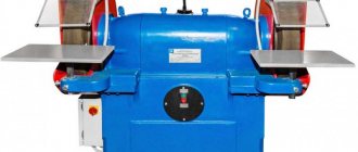
How to make a sharpening machine with your own hands - Metals, equipment, instructions
Currently, there are several types: a machine for sharpening knives, a machine for a hairdressing machine, and others. This article talks about how to make a machine for sharpening knives at home: detailed drawings with dimensions, photos and videos (2-3 videos) are presented.
Rules
Often, when sharpening knives at home, household members use abrasive whetstones. However, in order to use them in practice, you need the necessary skills and experience working with them. After all, if the knife is sharpened at the wrong angle, the blade remains dull.
Layout of the block to the blade.
Before actually manufacturing the machine, you need to listen to the advice of sharpeners.
When sharpening a knife, the master performs the following actions:
Defines the angle between the working area of the blade and the block. Moreover, for each model the angles are different;
Typically the angle is 25 degrees;
The mechanic begins processing from the beginning of the foot blade;
When adjusting the sharpening angle, the master paints over part of the foot blade with any marker. As a result, the mechanic directly controls the work area.
As a rule, after sharpening the working blade has non-uniform deformations. Therefore, when processing independently, the “point of reference” should not be the sharp part of the knife.
Choosing whetstones for sharpening a knife
The main indicator of a block is its grain size.
The whetstone is the main component that makes the blade thin and sharp. As a result, before choosing a design, you need to select the necessary blocks.
When sharpening knives on their own, household members use these types of whetstones
which have a high grain size. Using such bars, the shape of the leg blade is corrected.
having medium grain size. With the help of such bars, the mechanic removes the grooves that are formed during the initial processing of the knife
whetstone, which is covered with GOM paste. In such a situation, the mechanic polishes the blade.
When processing knives for the kitchen, you can use two types - with medium and high grain. And also in this case it is necessary to use a touchstone.
Base
When making a sharpening machine at home, you can use various parts. In particular, you can use laminated box plywood 12 mm thick, which was previously used to create radio equipment housings.
When constructing a machine at home, a household member performs the following actions:
Selects a base for such an installation, which must weigh at least 5 kg. Otherwise, it will be impossible to sharpen chopping devices and tools on the machine. Therefore, in the manufacture of such equipment, the tenant uses various steel angles measuring 20x20 mm;
Installs 3 parts between the inclined walls on the sides - an inclined surface made of plywood with dimensions of 230 x 150 mm.
In such a situation, the trapezoidal sides are located laterally on a rectangular surface.
The result is a base - a wedge. In such a situation, a protrusion of an inclined surface measuring 40 mm is formed in the front part;
Then, along the side wall ends, the mechanic marks 2 lines with a thicknesser. At the same time, it retreats by half the thickness of the plywood;
Drills the ends of the inclined surface and connects the base parts for a while;
At the back of the structure, the mechanic connects the side walls using a 60x60 mm block, which is attached to the end with two screws on both sides; — makes a 10 mm gap in the block.
In such a situation, it retreats 50 mm from the center - 25 mm from the edge. To maintain a vertical position, first drill with a thin drill from 2 edges, and then expand;
Then, at the top and bottom, two threaded fittings are screwed into the gap, and in the fittings - a 10 mm pin, the length of which is 250 mm.
If the threads do not match the studs, the lower fitting is adjusted.
Electric hammer for forging work
List of materials:
– car suspension spring; – steering rods; – wheel with disk and tire R14; – two VAZ wheel hubs; – channel, angle, sheet iron, profile pipes; – engine power 1.5 kW (1500 rpm); – bolts, nuts, washers; - a piece of rail.
Homemade manufacturing process:
Step one. Main stand
Let's start making a homemade product from the main stand; it is a structure in the shape of the letter “L”. Everything was done by welding the channel. Of course, everything must be cooked very reliably, since this part bears considerable loads.
This stand contains the axle on which the car wheel is mounted. Logically, the author uses a wheel hub from a VAZ as an axle. We make fasteners from sheet iron under the hub and weld them in place. We securely fasten the hub with bolts and nuts, and after that you can install the car wheel.
Step two. Engine frame
Next we make a frame for the engine, this structure is assembled from a corner. The frame is hinged to the main stand; as a result, the engine can move away or move closer to the wheel. Thanks to this design, we are able to control the clutch of the drive wheel with the driven wheel (car wheel). This is very convenient; you don’t need to constantly turn the engine on and off, even under load. The engine runs constantly, and we just press the pedal, operating the clutch.
We use a tube and a steel rod as a hinge; the backlash should be minimal. As for the engine, we remove the pulley from its shaft and install the drive wheel here. You can order this from a turner; for ease of manufacture, the part can be machined from aluminum.