The essence of turning is the formation of the surface of a part with a tool with a cutting edge, which, as a rule, rotates the workpiece and moves the cutter. The turning process is quite diverse in the shape and materials of the parts being processed, types of operations, processing conditions, requirements, cost and many other factors. Using roughing and finishing operations performed on CNC lathes, parts of various configurations are obtained with a surface finish Ra of up to 1.25, and in some cases even higher. Surface accuracy depends on the rigidity of the machine-tool-workpiece system, on the tool used and cutting modes: the harder the cutting edge of the tool (hard alloys, metal-ceramics, CBN, cubic boron nitride, diamond, etc.), the higher the rotation speed of the workpiece, the lower feed and overhang of the cutter, the better the surface cleanliness and accuracy.
| TS1625F3 | TS1720F4 |
There are several main types of turning operations, which include:
•processing of cylindrical surfaces;
•processing of conical parts such as shaft;
•design of complex surfaces of bodies of revolution, shaped turning, turning of fillets and roundings
•cutting of workpieces, processing of ledges;
•turning of grooves (external and internal);
•drilling holes;
•boring, reaming, countersinking of holes;
•cutting internal and external threads using cutters and tools: taps, threading heads.
•cutting blanks;
Machining of cylindrical surfaces
is one of the simplest operations for selecting the type of tool, calculating cutting conditions and programming processing.
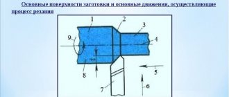
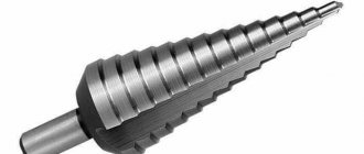
Turning is a combination of two movements - rotation of the workpiece and movement of the tool. In the case of processing cylindrical surfaces, the tool is fed along the axis of the rotating workpiece, thus removing the metal allowance, that is, processing the diameter of the workpiece. A type of external turning is the processing of stepped shafts using continuous thrust and scoring cutters.
On CNC machines, optimization of the turning process occurs in the direction of increasing speed and the ability to carry out processing with several tools in one setup, which allows both roughing and finishing processing to be carried out in one cycle. It is also important to increase control over the turning process, which ultimately affects the quality of the machined parts and the reliability of the entire operation.
When turning cylindrical surfaces on CNC machines, high turning accuracy is achieved thanks to the rigidity of the system, modern cutting tools and various processing control systems.
To ensure the rigidity of the machine-tool-workpiece system, the following methods of securing the workpiece are used:
1. when processing in a chuck - reducing the overhang of the workpiece (modern lathes have an enlarged hole in the spindle)
2. when processing long and heavy parts - fixation in the centers of the headstock and tailstock. As a rule, a rotating center is inserted into the quill and the workpiece is pressed with it. The drive faceplate transmits torque from the lathe spindle to the product.
2. Fastening parts with a relatively short length in a three- or four-jaw lathe chuck. Long workpieces can also be fixed in the spindle chuck, and their cantilever part is supported by a steady rest during cutting. The steady rest is installed on the guides of the frame or support.
3. Use combined (1 and 2) fastening of the workpieces.
4. Technological methods often include the ability to control the machine spindle at near-resonance frequencies (controlled oscillatory acceleration and deceleration of the spindle).
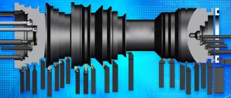
Effective performance of various turning operations requires the use of specially designed tools. More details about turning tools are described in the article:
The most well-known and widespread machining process control systems include machine tool sensors for monitoring the cutting edge of a tool. Accounting of cutting time for each tool and automatic change to a backup tool.
Turning tools
The main parameter for the productivity of lathes is the choice of the following cutting modes: the amount of longitudinal feed of the tool during processing, cutting speed and depth of the removed metal layer.
Proper use of these parameters will allow you to achieve:
- optimal rotation speed of the workpiece and speed characteristics of the part processing itself;
- increasing the wear resistance of the cutting tool with optimal forces of its impact on the surface of the part;
- necessary removal of a layer of metal shavings during turning;
- maintaining the working surfaces of turning equipment in perfect condition.
The cutting speed is also influenced by the type and grade of the material being processed, as well as the type and quality characteristics of the cutting tool used. By choosing the spindle speed and cutting speeds, you can influence the quality indicators of turning the part. Always taken into account indicators such as material density and other quality characteristics of workpieces can be found in specialized tables and reference books.
Depending on their purpose, turning cutters are divided into roughing - for pre-processing, and finishing - for making the final dimensions of the part. The geometric shape of the cutting part of the cutting plates allows you to remove both small and larger allowances.
According to the movement direction parameter, turning cutters are divided into right and left. The first move from right to left (from the tailstock to the front), the second, respectively, vice versa.
According to the geometric shape and type of cutting plate, the cutters are divided into bent, straight and reinforced. In the latter design, the width of the fastening part is significantly greater than the width of the cutter itself.
According to functionality, turning cutters are divided into:
- pruning;
- cutting;
- pass-through straight and persistent;
- threaded internal and external;
- boring;
- groove;
- shaped.
The quality and accuracy of cutting directly depend on the geometric parameters of turning tools. And with the correct choice of its shape, the most effective turning results are achieved. To do this, the turner needs to know such a technical concept as “lead angle”. This is the angle between the projections of the main and auxiliary cutting edges of the cutter onto the main plane:
- φ (angle of the main cutting surface);
- φ1 (auxiliary plane);
- ε (at the top).
The apex angle is ensured when sharpening the cutter, and the main and auxiliary ones also depend on its positioning during installation. If the main angle is large, the loads will be directed to a small area of the edge, and this will lead to a decrease in the life of the cutting tool. By decreasing this angle, the cutter will have a longer service life, heating of the cutting zone will be much reduced, which will lead to greater efficiency.
Turning of conical parts such as shaft
For this type of processing, CNC lathes have an undeniable advantage. Precise and productive turning of the conical surface of a part on universal machines is a labor-intensive operation that requires not only appropriate qualifications of the turner, but also additional devices (use of simultaneous feed along two axes (if technically possible), template, copy ruler). While the CNC machine carries out simultaneous longitudinal and transverse feed of the tool. This allows linear movements along the X and Z axes to be specified in one block when programming processing. In this block of the control program, the coordinates of the end point of the movement - the top of the cutter - are indicated. This programming method is the most universal, as it allows processing with any taper angle. Chamfering is often a standard CNC feature that speeds up the programming process.
Turning equipment
For all types of turning parts, different types of equipment are used, but today screw-cutting lathes are used everywhere in all industrial enterprises. They are universal in their technical capabilities, so they are widely used not only in large industrial enterprises, but also in small factories that produce products in small batches.
Structurally, universal screw-cutting lathes include the following main components:
- headstock with spindle and gearbox, tailstock with quill, body and longitudinal slide;
- gearbox;
- caliper;
- a frame with compartments in which the engines are located.
To obtain the most accurate dimensions during turning and milling processing, computer-controlled machines are used, which are not fundamentally different in design from universal-type equipment (examples of video recordings of turning and milling processing of various surfaces can be found on the Internet, where processing on different models of machines with from different angles).
In addition to the listed types of turning equipment, the following types of devices are also widely used in enterprises:
- screw-cutting lathes;
- rotary turning;
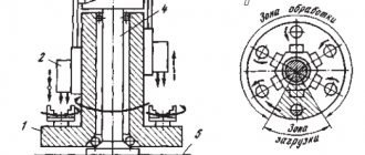
- turning-turret;
- multi-cutting semi-automatic machines suitable for the production of large-scale production of parts;
- modern complexes for performing turning and milling operations.
Design of complex surfaces of bodies of rotation, shaped turning
To obtain bodies of revolution with a curved generatrix on universal machines, it is necessary to use through or shaped cutters using a copier or a hydrocopying support. Often, such operations require highly qualified turners, and profitability is achieved only with mass production.
Modern CNC lathes have wide technological capabilities. Shaped surfaces are very diverse; their production in many cases is ensured not by the geometry of the tool, but by the form-building movements of the working parts of the machine according to the program. The use of shaped tools for working on CNC machines is extremely rare. Obtaining the full variety of part surface shapes can be achieved through proper design of the processing program. The accuracy of circular and linear interpolation allows for smooth transitions between frames.
This makes it possible to get by with a relatively narrow range of tools when processing various parts. The programmable point of the cutter is either its tip or the center of the rounding at the tip.
On CNC lathes, it is especially effective to use tools with multifaceted non-grinding inserts made of carbide and super-hard materials. They ensure stability of the geometry, the ability to use the maximum power of the machine, increased tool life, and simplify the setup of the machine when the tool wears out. When one of the cutting edges wears out, the plate is rotated, introducing a new edge into the work. The error in the position of the new face usually does not exceed 0.05-0.1 mm and can be easily eliminated using correctors of the CNC system.
Features of installation of cutters
The main requirement for fixing a part on a machine during finishing turning is the strength of the fastening in order to avoid displacement of the metal product being processed during processing. You need to be especially careful when the technical process provides for the processing of several surfaces with one workpiece secured, because if the part is displaced, the processed surfaces may not coincide and, as a result, the product will be rejected.
Fastening the part too firmly will also not do any good. For example, if you press a thin-walled ring tightly into a chuck, its shape may change. If finishing work immediately follows rough turning of cylindrical surfaces, shape changes can be avoided by loosening the chuck jaws before finishing machining.
Cutting a product or workpiece
is performed by cutting cutters, with the tool moving transversely to the center of the part. Depending on the size of the part, various methods of fixing an almost cut or cut part are used. Tool breakage at the end of cutting is prevented by using supporting rests and reducing the cutter feed (by 45-55%) when approaching the center of the part by half the radius of the workpiece. Small parts fall into a tray, part catcher or are fixed in a turret fixture.
Cutting tools for fine turning
When choosing a tool, preference should be given to those cutters that will help obtain a part with minimal roughness. Taking this requirement into account, the tool shape is selected. The best option is a through cutter, which is capable of providing the specified finishing finish.
Sometimes during the cutting process, the cutter literally tears out solid inclusions from the surface of the metal product being processed. In such cases, various depressions appear on the surface of the metal, impairing the cleanliness of machining. That is why, if increased precision requirements are placed on a part, a spring holder is used in which the cutting tool is installed. Thanks to this device, the cutting edge does not tear out these inclusions, but smoothes them out.
When working with a spring-loaded tool, you can achieve better results if you process the surface not in one, but in two or more passes. This approach is recommended for use in the manufacture of critical parts in single production. However, we must not forget that performance deteriorates.
When finishing turning cylindrical surfaces, chips with a small cross-section are formed. Such work is carried out at high speeds, so when choosing a tool material, care must be taken to ensure that the cutter retains its physical, mechanical and operational properties during the work. In other words, it is necessary to select a cutting edge material that will provide high wear resistance.
According to the requirements that a metal-cutting tool must meet, when working with steel and cast iron workpieces, it is better to use cutters made of high-speed steel, hard alloys, and mineral ceramics. In addition to these materials, cermets are increasingly used in the manufacture of cutters.
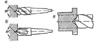
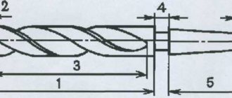
Drilling, countersinking, reaming holes
The main method of making holes is drilling. Drilling is the process of making cylindrical holes using a metal-cutting tool. Drilling usually precedes operations such as boring or reaming. Processing can be done either in the center of the part (when clamping it in a three-jaw chuck) or with an offset of the center of the hole. Offset (eccentricity) is achieved by fixing the workpiece in a four-jaw lathe chuck or on the headstock faceplate. On a turning center, it is possible to use a driven tool and make holes both on the spindle axis and with an offset along the X axis. When using a radial drive unit, it is possible to process holes located along the X axis.
In a universal machine, the processing tool: countersink, drill, reamer is fixed in the conical hole of the tailstock directly or through a clamping chuck. in CNC machines - in the toolholder position using special cutting blocks and mandrels.
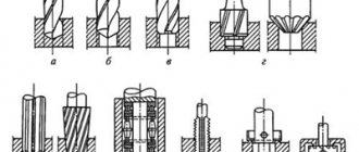
With the development of tools for machining short holes, the sequence of the drilling process and preparation for it undergoes significant changes. Modern tools allow drilling into solid material and do not require preliminary centering of the holes. High surface quality is achieved and, often, there is no need for subsequent finishing of the hole. The use of modern drills with replaceable inserts allows processing at high speeds and large volumes of generated chips, which in CNC machines are washed out of the hole by flows of coolant supplied under a certain pressure through internal channels.
For precision turning, it is necessary to have correct and uniform sharpening of the cutting edges of the drill, perpendicularity of the end of the workpiece to the tool axis, and the absence of burrs and surface irregularities.
Using Renishaw monitoring and setting systems, software in CNC machines allows you to set tool length and diameter compensation parameters and perform breakage detection during machining. The tool feeding in the machine occurs mechanically. The drill ensures a clean surface of the hole Ra 6.3...3.2, a countersink - Ra 2.5, a reamer - Ra 1.25...0.8.
Causes of defects during turning and their elimination
With any type of turning of metal parts, the following deviations from the specified conditions may occur.
1. Surface roughness parameters do not meet the requirements specified in the drawing.
This deviation occurs mainly for the following reasons:
- high feed speed is set;
- wear of the bearings in the spindle assembly or unreliable fastening of the workpiece in the lathe chuck leads to vibration of the part when cutting forces are applied;
- increased gap between the caliper mating parts;
- unreliable fastening of the cutting tool;
- the radius of curvature of the tool cutting edge is too small;
- improper sharpening of the cutter;
- increased viscosity of the material;
- choosing a cutter with incorrect geometric parameters.
The above quality violations can most often be eliminated by reducing the processing allowance removed or reducing the feed rate.
2. The appearance of an oval-shaped surface after turning.
The workpiece may become oval due to spindle runout for three reasons:
- Uneven bearing wear.
- Uneven wear of the spindle journal seating surfaces.
- Penetration of small chips, dirt or other particles into the tapered part of the spindle bore.
Such problems are eliminated by:
- periodic checks of machines for rigidity;
- Regular cleaning of conical centers and holes;
- carrying out timely repairs of equipment.
3. Appearance of taper after surface treatment.
Most often, the cause is a misalignment of the rear and front centers due to small chips or dirt getting into the tailstock quill hole. To eliminate this cause of the violation, you must:
- check the correct installation of the rear center;
- clean the center and conical hole of the quill;
- adjust the location of the tailstock along its guides (if necessary).
4. After turning, the part is made with inappropriate dimensions.
Violation of overall dimensions during machining of parts will most likely occur due to:
- incorrectly set cutting depth;
- incorrect measurement during preliminary grinding.
If the outer diameter of the part is smaller than required or the inner diameter is larger than required, then the defect is classified as irreparable. In opposite cases, you can remove another layer to bring it to the required size. In this case, the marriage, accordingly, is correctable.
5. The surface is not completely processed.
This violation occurs for the following reasons:
- the initial parameters of the workpiece are determined incorrectly;
- there is no necessary allowance for processing;
- increased curvature of the workpiece;
- incorrect installation of the part;
- inaccurate alignment of the workpiece during installation;
- displacement of the location of the center holes;
- violation of the location of the posterior centers.
In frequent cases, this type of marriage cannot be corrected. To avoid its occurrence, you must:
- ensure that the holes are positioned correctly;
- regularly and timely check the alignment of the centers;
- make sure that the workpiece is installed securely and correctly;
- correctly set the required values of allowances for processing;
- Before processing, carefully measure the workpieces;
- at the moment of fastening in the lathe chuck, check for runout.
Before starting work on turning equipment, it is necessary to practice on defective parts in order to identify the features of the machine in order to achieve higher productivity and accuracy.
By applying all the recommendations and instructions listed above, you will be able to obtain satisfactory results and avoid unwanted and unexpected consequences when working on turning equipment.
Boring holes
Precise holes, large-diameter stepped holes, and internal grooves can be produced using boring operations. The product is clamped into the headstock chuck and supported by a steady rest (in the case of significant length or weight). In this case, access to the end processed by the boring cutter remains free. The accuracy of boring on a CNC lathe exceeds the accuracy of drilling, and is often ensured by processing technology, cutting tools, lathe experience, systems for fine-tuning cutting tools and the technical condition of the equipment.
Main types of metal turning work
Modern lathes allow you to perform various transitions with the workpiece, which can be divided into external and internal. External operations change the outer diameter of the workpiece, and internal operations change its internal dimensions. Each of the subsequent turning transitions is determined by the type of cutting tool used and the trajectory of this tool, which ensures metal removal.
In classical external contour turning, a single-edge metal-cutting tool moves axially along the outer surface of the workpiece, removing material and forming various elements: steps, cones, chamfers, etc. These elements are usually machined with a small radial tool feed. Several passes of the cutter are possible until the final diameter values set by the requirements of the drawing are achieved.
The following are considered specific transitions when turning metals:
- Facing is the process of obtaining a smooth, even surface on one of the ends of the workpiece. The face can be produced in one or more passes, depending on the axial depth of cut.
- Grooving, for which the cutter moves with a radial feed, forming a groove whose width corresponds to the width of the tool. Special tools can be used to form grooves of various geometries.
- Cutting off is a transition for which the cutter moves with a radial feed until it reaches the center or inner diameter of the workpiece.
- Cutting external threads, for which a cutter (usually with a pointed end at an angle of 600) is moved in the axial and radial directions, forming a thread on the external surface. The thread can be cut to a specific length and pitch, and several passes may be required to form it.
Internal operations:
- Drilling in which the drill is inserted into the workpiece in the axial direction, producing a hole with a diameter equal to the diameter of the tool.
- Boring, when the diameter of a previously obtained hole is increased. When boring, various internal elements are also obtained - steps, cones, chamfers, etc. Boring is usually done after drilling.
- Reaming - through this transition, as with boring, the existing hole is enlarged. Unlike reaming, this involves removing a minimal amount of material to create a smoother interior surface.
- Cutting internal threads, which is performed with a tap, with its axial feed. A hole is usually drilled into the existing hole, the diameter of which is equal to the diameter of the tap lead.
Metal turning also involves other, specialized transitions that use the rotation of the workpiece.