Classification and thread parameters
Threads are classified according to the following characteristics:
- according to the profile of the screw surface: triangular, trapezoidal, thrust;
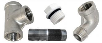
- according to the shape of the surface on which the thread is made: cylindrical and conical, external and internal;
- in the direction of the screw movement of the threaded contour: right and left;
- by number of passes: single- and multi-pass;
- by operational purpose: general use and special.
Threads for general use include:
- a) fastenings (metric, inch). The main requirement for them is to ensure the strength of the connection and maintain the tightness of the joint during long-term operation;
- b) kinematic (trapezoidal and rectangular) for lead screws. The main requirement for them is to ensure accurate movement with the least friction;
- c) pipe and fittings. The main requirement for them is to ensure tight connections.
Thrust threads are used to convert rotational motion into translational force (jacks, presses). The main requirement for it is to ensure high load capacity.
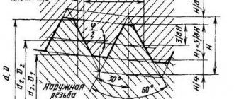
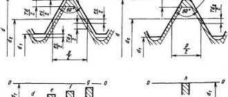
Thread parameters. In general mechanical engineering, metric threads are most widely used. GOST 24705-81 establishes the nominal profile of metric threads and the dimensions of profile elements.
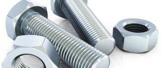
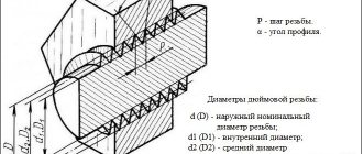
d - outer diameter of the external thread (bolt); D —outer diameter of the internal thread (nut); d2 is the average diameter of the bolt; D2 - average diameter of the nut; d1 is the inner diameter of the bolt; D1 - internal diameter of the nut; d3 is the internal diameter of the bolt along the bottom of the cavity; P —profile pitch; H is the height of the original triangle; α = 60° – thread profile angle; R is the nominal radius of curvature of the bolt root;
The average diameter of the thread (d2, D2) is the diameter of an imaginary cylinder coaxial with the thread, the generatrix of which intersects the thread profile at the points where the width of the groove is equal to half the nominal thread pitch.
The outer diameter of the thread (d, D) is the diameter of an imaginary cylinder described around the tops of the external threads or the valleys of the internal threads.
The internal diameter of the thread (d1, D1) is the diameter of an imaginary cylinder inscribed tangentially to the recesses of the external thread or the crests of the internal thread.
Thread pitch (P) is the distance between adjacent profile sides of the same name in a direction parallel to the thread axis.
Thread profile angle (α) – the angle between the sides of the profile.
The height of the original profile (H) is the height of the acute-angled profile obtained by extending the sides of the profile until they intersect.
The working height of the profile is the height of contact between the sides of the profile of the external and internal threads in the direction perpendicular to the thread axis.
Make-up length (L) – the length of contact of the screw surfaces of external and internal threads in the axial section.
GOST 8724-81 sets thread diameters from 0.25 to 600 mm and pitches from 0.075 to 6 mm. There are 3 rows of metric thread diameters installed. When choosing a thread diameter, you should prefer the first row to the second, the second to the third.
Transitional landings
Fitments intended for steel parts with external threads mating with internal threads in parts made of steel, cast iron, aluminum and magnesium alloys.
The make-up length is similar to the lengths for interference fits. Transitional fits ensure precise centering, for example M12-4Н6(2)/ 4jk), assembly and disassembly is possible.
Monitoring the accuracy of threaded parts
Measuring the average diameter of a thread using the three-wire method
Cutting tools
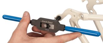
A tap is used to cut internal threads. This is a special screw that has hard cutting edges. This tool consists of a working part and a shank designed for fixation in the driver. The device can be manual or machine.
Locksmith kit contents:
- Tap. Its diameter can vary and reaches 18 mm.
- Two rough working parts.
- Rough tap of a different diameter, medium and finishing.
The product is marked in the same way as bolts. That is, it has a letter and number designation. But it also has risks that show its type (rough, medium, finishing).
Before you start cutting, you must first make a hole that will have a slightly smaller diameter. During operation, the tool must be held perpendicular and lubricant added to the cutting area. The tap should be unscrewed every few turns to remove accumulated metal shavings. This is very convenient to do with a small special brush.
On an industrial scale, external threads are made on a machine. For household needs, dies are used, which are:
- Split. The tool is made of two halves, which is why it is not as rigid as other types. Can be used for undemanding connections.
- Whole round. With this die you can cut high-quality threads.
- Sliding. Used in clamps. You can make pipe threads.
The die itself looks very similar to a regular nut, inside of which there are cutting edges. The tool can be designed for cutting metric or inch threads.
Specification for Threaded Fasteners with Metric Threads
To characterize the mechanical properties of threaded and fasteners, classes and strength groups are provided depending on the material and manufacturing process (Table 1).
The choice of material depends on the operating conditions and technical requirements for the design of the machine or mechanism. Table 1. Fasteners with metric threads. Strength classes according to GOST 1759-70
| Name of fasteners | Material grade | Strength class or group designation | ||
| Bolts | Steel 10kp GOST 1050-74 | 4,8 | ||
| Steel 35 GOST 1050-74 | 5,6 ; 6,6; 8,8 | |||
| Steel I2XI8H9T GOST 5032-72 | 21 | |||
| Screws | Steel 10kp GOST 1050-74 | 4,8 | ||
| Steel 35 GOST 1050-74 | 5,6 ; 8,8 | |||
| L63 GOST 15527-70 | 32 | |||
| Steel 12x18N9T GOST 5532-72 | 21 | |||
Set screws | Steel 35 GOST 1050-74 | 14H; 22H; 33N | ||
| Steel I2Х18H9T GOST 5632-72 | 21 | |||
| Nuts | Steel 10kp GOST 1050-74 | 5 | ||
| Steel 35 GOST 1050-74 | 6; 8 | |||
| L63 GOST 15527-70 | Z2 | |||
| Steel I2XI8H9T GOST 5632-72 | 21 | |||
| Nuts are low | Steel 10kp GOST 1050-74 | 04 | ||
| L63 GOST 15527-70 | 32 | |||
| Rivets | Steel 10kp GOST 1050-74 | 01 | ||
| L63 GOST 15527-70 | 32 | |||
| M3 GOST 859-78 | 38 | |||
| AD1GOST 4784-74 | 37 | |||
| Washers | Steel 08kp GOST 1050-74 | 01 | ||
| Steel 35 GOST 1050-74 | 05 | |||
| Steel I2ХI8HI0T GOST 5632-72 | 21 | |||
| L63 GOST 15527-70 | 32 | |||
| Pins | Steel 45 GOST 1050-74 | — | ||
| Hairpins | Steel 10kp GOST 1050-74 | 5,8 | ||
| Steel 35 GOST 1050-74 | 5,6 ; 6,6; 8,8 | |||
| Cotter pins | Steel 10kp GOST 1050-74. | 0 | ||
| Ears for springs | Steel 10kp GOST 1050-74 | 4,8 | ||
| Steel 35 GOST 1056-74 | 5,6 | |||
| Note. The rectangular frames indicate the values of the strength classes (groups) of the preferred application. | ||||
Types of coatings for threaded fasteners are selected depending on the material, manufacturing process and operating conditions imposed on the structure (Tables 2, 3).
Table 2. Fasteners with metric threads. Types of coatings
| Type of coverage | Coverage designation | |
| according to GOST 9.306-85 | digital | |
| Zinc chromated | C. hr | 01 |
| Cadmium, chromated* | Kd. xp | 02 |
| Copper-nickel, multilayer | M. N | 03 |
| Oxidized, oil-impregnated | Chem. ok. prm. | 05 |
| Tin | ABOUT | 07 |
| Nickel | N | 13 |
Notes:
* Cadmium chromated coating is used for products intended for use in tropical climates | ||
Table 3. Fasteners with metric threads. Coating thickness
| Products with thread | Products without thread | |
| thread pitch, mm | thickness, µm | thickness, µm |
| From 0.4 to 0.45 | 3 | 6-9 |
| From 0.5 to 0.75 | 6 | |
| From 0.8 to 5 | 9 | |
Symbol for trapezoidal thread (GOST 9484-81)
The definition of a single-cut trapezoidal cutting contains the abbreviation Tr, the value of the outer gauge and the pitch. Example: Tr16x4. For a multi-start trapezoidal cut, the definition includes: the combination of Tr, the external diameter, as well as the pitch and stroke. Example: Tr16x8(P4)LH.
Trapezoidal thread (GOST 9484-81).
Designation of persistent reinforced thread (GOST 13535-87)
The definition of persistent reinforced cutting contains the letters S, as well as an angle of 45, caliber and pitch. Example: S45200-13. If the thread is left-handed, the letters LH are additionally indicated. If it is necessary to define a multi-start thread, then indicate the letter S, the angle 45, the diameter, the stroke and the symbol P along with the pitch value, highlighted in brackets. Example: S4520024(P12) - two-start, stroke value 24 mm, pitch - 12 mm. For left-sided cuts, additionally LH is indicated.
Reinforced thrust thread (GOST 13535-87).
Symbol for metric thread (GOST 8724-2002)
The definition of a thread includes the letter M (from the English metric system), the size of the gauge and the pitch of the thread, delimited by the sign “x”. Example: M8x1.25. It is possible not to specify a large step. Example: M8. If the thread is left-handed, then the letters LH are added. Example: M8x1-LH. The definition of a multi-start cut consists of the symbol M, the diameter, the sign “x”, the combination of Ph, the stroke, the symbol P and the pitch. For certainty, you can specify the number of visits.
Metric thread (GOST 8724-2002).
What is the image and designation of the thread
The designation allows, based on a combination of letters and numbers, to understand what type of cutting is presented for analysis. It includes: type, pitch and stroke, accuracy class and number of the corresponding standard. For a better understanding of the operation, an image is used - this is a drawing in which, in accordance with GOST, a structural element with a threaded surface is presented.
The diagram helps create a visual representation of the shape and geometric features of the carving.
Basic information and areas of application
Most often, the threaded connection is made in the metric system. Thread sizes can be completely different. The coils are applied to the external or internal surfaces of any cylindrical element. This is the type of the most common fasteners:
- Nuts.
- Hairpins.
- Bolts.
- Screws (including those with a countersunk nut, requiring special holes prepared by countersinking).
- and so on.
Any of these parts has a thread run-out. In many technical specialties, drawing training begins with an image of the section and profile of a bolt. Such sketches are also present in the documentation for the technical operation of devices.
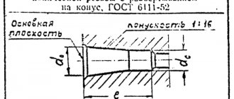
Products with a conical shape with a metric thread type are needed in cases where the connection requires high tightness. The angled profile eliminates the need for additional seals. This type has proven itself successfully during the installation of pipelines through which liquids and gases move. Pipe threads at low media pressures do an excellent job without gaskets. The conical type is also used when creating lids for various containers to seal the hole.
There is also a less common type of thread. It is called tape (rectangular). This type is used mainly in mechanical engineering.
The metric type of connections has a number of such parameters:
- Diameter.
- Thread pitch.
- Thickness and location.
- Height.
- Direction of turns.
To understand what a thread pitch is, just look at a regular bolt (it doesn’t matter whether it’s a hex head or a standard one). This is the distance between individual turns. There are other parameters due to which metric connections are divided into types that have their own symbols of letters and numbers.
Threaded connections have gained immense popularity due to a large number of advantages, including:
- Reliability and long service life.
- Ability to adjust the compression ratio.
- Simplicity of design.
- Fixation in a twisted position.
One of the disadvantages is the uneven distribution of the rated load over the entire width and length of the turns. If you frequently disassemble and reassemble the structure, this accelerates the wear of the elements. To extend service life, it is advisable to chamfer each time to the depth of the damage, but this is not applicable in all cases. Also, parts with different pitches will not fit together.
Designation of thrust thread (GOST 10177-82)
The definition of a thrust thread must contain the letter S, the pitch and the value of the diameter. Example: S90-10. For left-sided cuts, additionally LH is indicated. If multi-pass cutting is considered, then its definition is made up of the symbol S, diameter, stroke and in brackets the letter P, the value of the step. Example: S80-20(P20).
Thrust thread (GOST 10177-82).
