14.1. Design and geometric parameters of a twist drill
The following parts are distinguished in a twist drill (Fig. 14.2).
Working part
– part of the drill equipped with two spiral (more precisely, helical) grooves; the working part includes the cutting and guiding parts of the drill.
Cutting part
- part of the drill, sharpened to a cone and bearing the cutting edges.
Guide part
– part of the drill that provides direction for the drill during the cutting process.
Shank
- part of the drill that serves to secure it and transmit torque from the spindle.
Paw
(for drills with a conical shank) serves as a stop when knocking the drill out of the spindle hole.
Rice. 14.2. Drill components
The main elements of a twist drill (Fig. 14.3).
Front surface
1
is the helical surface of the groove along which chips flow.
Main back surface 2
– surface facing the cutting surface.
Auxiliary rear surface (ribbon)
3
– a narrow strip on the cylindrical surface of the drill, located along the helical groove; Provides direction to the drill when cutting.
Main cutting edge 4
– an edge formed by the intersection of the front and main rear surfaces.
Secondary cutting edge 5
– an edge formed by the intersection of the front and auxiliary rear surfaces.
Cross edge 6
– formed at the intersection of two main rear surfaces.
Blade top 7
– the intersection point of the main and auxiliary cutting edges.
Drill back 8
– a surface lowered relative to the ribbon, designed to reduce friction between the drill and the machined surface of the hole.
Rice. 14.3. Drill blade surfaces and cutting edges
The two main cutting edges (see Fig. 14.2), located on the cutting part (fence cone), form an apex angle of 2φ, which for drills made of tool steels when processing structural materials is usually equal to 116...118°; for different materials it should be different: for harder ones - more, for softer ones - less. For example, when processing heat-resistant and stainless materials, drills with an angle of 2φ = 125...135° (for a blind hole) and 2φ = 140° (for through holes) have maximum durability; when processing ebonite, marble and other fragile materials, the angle 2φ = 80...90°; when drilling titanium alloys 2φ = 90…120°; when drilling aluminum and aluminum alloys 2φ = 130…140°.
Cross edge angle
ψ is measured between the projections of the transverse and main cutting edges onto a plane perpendicular to the drill axis; with proper sharpening of the drill, the angle ψ = 50...55°.
The inclination of the helical groove along which the chips flow is determined by the angle ω between the axis of the drill and the tangent to the helical line along the outer diameter of the drill. This angle ω, called the helical groove angle
drill, determines the value of the rake angle: with increasing angle ω, the rake angle increases and thereby facilitates the chip formation process. The inclination of the screw groove of drills is taken from 18 to 30°. As the angle ω increases, the strength of the drill decreases, as a result of which it becomes smaller for small-diameter drills than for large-diameter drills.
Geometric parameters of the cutting part of the drill.
The angles of the cutting edges of the drill are considered in a static state and during the cutting process (in motion). Let's consider a drill as a geometric body in a static coordinate system.
Static coordinate system
– a rectangular coordinate system with the origin at the considered point of the cutting edge, oriented relative to the direction of the speed of the main cutting movement (Fig. 14.4,
a
).
The main plane
P V is
a coordinate plane drawn through the point of interest on the cutting edge perpendicular to the direction of the speed of the main cutting movement at this point.
Cutting plane
P n is
a coordinate plane tangent to the cutting edge at the point under consideration and perpendicular to the main plane
P V
.
The main cutting plane
P
τ
is
a coordinate plane perpendicular to the intersection of the main plane and the cutting plane.
Working plane Р s –
the plane in which the directions of the velocities
V
and
V s
of the main cutting movement
D r
and the feed movement
D s
.
Rice. 14.6. Static drill angles in the main secant and working planes for various points of the cutting edge
Main rake angle
γ is the angle in the main secant plane
P
τ
– P
τ between the front surface
A
γ of the blade and the main plane
P V – V
.
The rake angle of the drill at an arbitrary point x
of the cutting edge is clearly shown in Fig.
14.7. The front angles γ and γ s
in the main cutting plane
P
τ
– P
τ and the working plane
P s – P s
are determined as follows.
In Fig. Figure 14.8 shows the development of helical lines lying on cylinders with diameters D
,
D
1,
D
2. From Fig. 14.8 it can be seen that the front angles in the working plane for the points under consideration will be equal:
,
,
.
Rice. 14.7. Rake angle measurement diagram
For an arbitrary point of the cutting edge lying on the diameter D x ,
will have
,
where H
– pitch of the helical flute of the drill, mm.
Since at any point X
cutting edge, the pitch of the drill helix
H
remains constant, then we can write
.
In the main cutting plane P
τ
– P
τ rake angle is determined by recalculation using the formula
.
The final recalculation formula has the form
.
Source
Metal cutting tool
A countersink is a metal-cutting tool for processing finished holes. A countersink can make a hole cleaner than a drill because the countersink has more cutting edges. Typically a countersink has three or four helical flutes, and therefore the same number of cutting edges. A tapered countersink, called a countersink, is used to deepen the entrances of holes for countersunk screw heads. To prepare a hole for a cylindrical or semicircular screw head, use a cylindrical countersink with a guide. Just like drills, countersinks are made with cylindrical or tapered shanks.
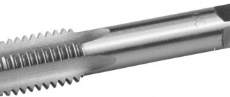
A tap is a tool used to cut threads in holes. A tap is essentially a screw in which longitudinal grooves are made. These grooves form the cutting edges. Typically, a set of taps is used to make threading by hand easier. The set consists of rough, medium and finishing taps.
The first to use is a roughing tap, which removes rough chips and cuts rough threads. Then use the middle and finishing taps. It is the finishing tap that finally calibrates the thread. Each tap is marked with thread size. In addition, on the shank of each tap there are one, two or three circular marks, which determine whether a rough, medium or finishing tap is used.
When cutting a thread manually, the tap is rotated with a crank. When starting work, you need to install the tap coaxially with the hole being cut. Otherwise, the thread will go askew or the tap will break. Typically, when cutting a thread by hand, the tap is turned one turn forward, then ¼ turn back, etc. As a result, the removed chips are crushed. In order to get a cleaner thread and make work easier, the tap must be moistened with: an emulsion solution - when cutting holes in mild steel or brass, drying oil - when cutting hard steel, kerosene - when cutting aluminum.
A hacksaw blade is a cutting tool for manually cutting metal. A hacksaw blade is a steel strip with triangular teeth cut on its edge, with a pitch (distance between teeth) of 0.8mm - 1.6mm. When making a hacksaw blade, the teeth are set so that the thickness of the blade is 0.25 mm - 0.5 mm less than the width of the cut. To increase hardness and reduce tooth wear, the hacksaw blade is subjected to heat treatment.
A hacksaw machine is used to cut metal with a hacksaw blade. Blades that become dull during operation are replaced. Sometimes, to increase the service life of the hacksaw blade, teeth are applied to it on both sides.
A thread die is a tool used to cut threads on bolts, screws, studs and other cylindrical parts. The sliding (prismatic) die is used for cutting threads with a die. It consists of two plates with semicircular threaded cutouts.
The cutting edges in a round die (die) are formed in holes with cutouts. The size of the thread to be cut is indicated on the flat surface of the die. A slot made in the die allows you to change the thread diameter within small limits. The new die does not have a cutout, but only a notch. In order to make the die adjustable, it is necessary to cut it with a thin grinding wheel. A crank is used to rotate the die. One of the screws entering the slot of the die can slightly expand the diameter of the thread, and the other two can compress it from the sides, thereby reducing the diameter.
A reamer is a tool used for precise finishing of holes. The reamer consists of a cutting (taking) part, a calibrating part, a neck and a shank. The shank of a reamer can be cylindrical with a square at the end for manual work, or conical for clamping into a machine spindle. A crank is used to rotate the reamer manually. To store reamers, protecting the cutting edges from nicks, use a wooden box divided into compartments by cardboard.
A drill is a cutting tool that is used to make holes in metal and other materials. Twist drills have two helical flutes cut into the working part of the drill. The chips that are formed during drilling exit through helical grooves. There are narrow guide strips located on the edges of the screw grooves. The central axial solid part of the drill is called the core and serves to increase the strength of the drill. The thickness of the core increases towards the shank. The shank does not have screw grooves and is used to secure the drill on the drilling machine. Drill shanks can be tapered or cylindrical. A drill with a tapered shank is inserted into the machine spindle. When the drill is knocked out of the spindle, a wedge is pressed against the tab of the conical shank. Drills with a cylindrical shank are installed in chucks.
Conventional drills are made of cast steel, which can be judged at the time of sharpening by the type of sparks that appear during sharpening: cast steel sparks have a light yellow color. High-speed steel drills have higher durability and good resistance to heat during the drilling process. High speed steel sparks are orange in color. The ends of two spiral feathers twisted around the core are sharpened so that the cutting edges form an angle of 120°. In this case, a pair of cutting edges is formed, with a bridge between them. The length of the cutting edges must be the same, otherwise the diameter of the drilled hole will be larger than the diameter of the drill. The back angle of the drill, which prevents friction on the back surface of the drill, is taken equal to 12-15°.
Large workshops have machines for sharpening drills. However, most often, in small workshops, drills are sharpened by hand. It takes some skill to sharpen a drill bit properly. The sharpening accuracy can only be determined using a reference gauge. When sharpening, it is necessary to set the drill at an angle to the plane of the circle and its periphery and rotate it relative to the axis, while simultaneously moving the drill shank to the left.
Novice workers sharpen without performing these movements; as a result, the back surface is flat, but the apex angle formed by the cutting edges will be correct. Then, as they gain experience, they can sharpen by rotating and moving the drill, which will allow them to obtain a conical flank. The intersection of these two rear conical surfaces forms a central edge, inclined to each cutting edge at an angle of 130°.
A correctly sharpened drill has two cutting edges working and chips exit along both spiral flutes. A drill that is sharpened incorrectly has only one cutting edge working, and the chips exit through only one spiral groove.
Say “thank you” to the author.
politexno.ru
Twist Drill Geometry
Drilling is one of the most common methods for making a hole. The cutting tool is a drill, which is used to make a hole in a solid material or increase the diameter of a previously drilled hole (reaming). The cutting movement during drilling is rotational, the feed movement is translational. The cutting part of the drill is made of tool steels (P18, P12, P6M5, etc.) and hard alloys. According to their design, drills are distinguished: spiral, with straight flutes, feather, for deep holes, for annular drilling, centering and special combined. Structural elements include: drill diameter D
, angle of the cutting part (apex angle), angle of inclination of the helical groove w, geometric parameters of the cutting part of the drill, i.e.
respectively, front g and rear a angles and cutting angle d, core thickness d
(or core diameter), feather (tooth) thickness
b
, ribbon width
f
, reverse taper j1, cutting edge shape and drill groove profile, working part length
l
o, total drill
length L.
Cutting tool
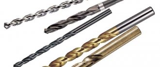
Drilling is one of the common methods for pre-machining holes on lathes. Depending on the design and purpose, drills are distinguished: spiral, feather, for deep drilling, centering, ejector, etc. The most widespread are spiral drills (In the picture, drills: a - spiral with a conical shank, b - spiral with a cylindrical shank, c - for deep drilling). The drill has: two main cutting edges formed by the intersection of the front helical surfaces of the grooves along which the chips flow with the rear surfaces facing the cutting surface; a transverse cutting edge (jumper) formed by the intersection of both rear surfaces; two auxiliary cutting edges formed by the intersection of the front surfaces with the surface of the strip. The drill strip is a narrow strip on its cylindrical surface, located along the helical groove and providing direction for the drill when cutting. The inclination angle of the helical groove is the angle between the drill axis and the tangent to the helical line along the outer diameter of the drill (ω = 20-30 degrees). The inclination angle of the transverse cutting edge (jumper) ψ is an acute angle between the projections of the transverse and main cutting edges onto a plane perpendicular to the axis of the drill (ψ = 50-55 degrees). Angle of the cutting part (angle at the tip) 2φ - the angle between the main cutting edges at the tip of the drill (φ = 118 degrees). Rake angle γ is the angle between the tangent to the front surface at the point in question on the cutting edge and the normal at the same point to the surface of rotation of the cutting edge around the axis of the drill. Along the length of the cutting edge, the rake angle γ is a variable value. Rear angle α is the angle between the tangent to the rear surface at the point in question of the cutting edge and the tangent at the same point to the circle of its rotation around the axis of the drill. The back angle of the drill is a variable value: α = 8-14 degrees at the periphery of the drill and α = 20-26 degrees closer to the center of the drill. What do aluminum/stainless steel blind rivets look like?
1 - cutting edge, 2 - front surface, 3 - rear surface, 4 - transverse edge, 5 - groove, 6 - ribbon
turner.narod.ru
Drill. Geometry elements
Drilling is one of the common methods for pre-machining holes on lathes. Depending on the design and purpose, drills are distinguished: spiral, feather, for deep drilling, centering, ejector, etc. The most widespread are spiral drills (In the picture, drills: a - spiral with a conical shank, b - spiral with a cylindrical shank, c - for deep drilling). The drill has: two main cutting edges formed by the intersection of the front helical surfaces of the grooves along which the chips flow with the rear surfaces facing the cutting surface; a transverse cutting edge (jumper) formed by the intersection of both rear surfaces; two auxiliary cutting edges formed by the intersection of the front surfaces with the surface of the strip. The drill strip is a narrow strip on its cylindrical surface, located along the helical groove and providing direction for the drill when cutting. The inclination angle of the helical groove is the angle between the drill axis and the tangent to the helical line along the outer diameter of the drill (ω = 20-30 degrees). The inclination angle of the transverse cutting edge (jumper) ψ is an acute angle between the projections of the transverse and main cutting edges onto a plane perpendicular to the axis of the drill (ψ = 50-55 degrees). Angle of the cutting part (angle at the tip) 2φ - the angle between the main cutting edges at the tip of the drill (φ = 118 degrees). Rake angle γ is the angle between the tangent to the front surface at the point in question on the cutting edge and the normal at the same point to the surface of rotation of the cutting edge around the axis of the drill. Along the length of the cutting edge, the rake angle γ is a variable value. Rear angle α is the angle between the tangent to the rear surface at the point in question of the cutting edge and the tangent at the same point to the circle of its rotation around the axis of the drill. The back angle of the drill is a variable value: α=8-14 degrees at the periphery of the drill and α=20-26 degrees closer to the center of the drill.
1 - cutting edge, 2 - front surface, 3 - rear surface, 4 - transverse edge, 5 - groove, 6 - ribbon
turnercraft.ru
"Eternal" drill
Drilling is the operation of making round holes in the solid material of a workpiece using a cutting tool called a drill.
Increasing the diameter of an existing hole in a part using a drill is called drilling, and making shallow (non-through) holes in solid material is called drilling.
Drill
According to the design and nature of the work performed, drills are divided into the following groups: feather, spiral, centering, annular (Fig. 1).
Rice. 1. Drills
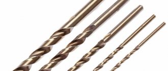
Drills are made from tool carbon, alloy or high-speed steels. In each group, drills can be equipped with carbide inserts.
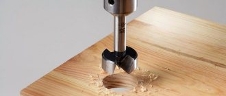
Feather drills
Feather or flat drills are simple in design, cheap to manufacture, can be made independently, and are little sensitive to distortion during operation. Feather drills can be double-sided or single-sided; they differ only in the form of sharpening the cutting edges (Fig. 2).
Rice. 2. Feather drill: a) for wood; b) for plastic
Feather drills have a flat cutting part with two cutting edges located symmetrically relative to the drill axis and forming a cutting angle of 45°, 50°, 75°, 90°.
The diameter of the drill is measured by the width of the blade. The thickness of the feather at the cutting ribs depends on the diameter of the drill and is:
- for drills with a diameter of 5...10 mm from 1.5 to 2 mm;
- with a diameter of 10...20 mm from 2 to 4 mm;
- with a diameter over 20 mm from 6 to 8 mm.
When the cutting edges intersect, they form a straight line, which is called a transverse edge, or jumper.
The disadvantage of feather drills is the lack of automatic chip removal during drilling, which damages the cutting edges and forces you to frequently remove the drill from the hole being drilled. In addition, feather drills lose direction during operation and decrease in diameter when regrinding.
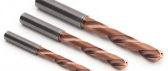
Twist drills
Rice. 3. Twist drills
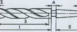
Twist drills have the widest application. A twist drill (Fig. 3) is a cylindrical rod, the working part of which is equipped with two helical spiral grooves designed to remove chips and form cutting elements. The inclination of the grooves to the drill axis is 10...45° (Fig. 4).
Rice. 4. Inclination of the grooves to the drill axis
The working end of the drill has a cone-shaped shape. On the generatrices of this cone lie two cutting edges symmetrically located relative to the axis of the drill.
The shank is designed to secure the drill.
Twist drills are made with cylindrical, conical hexagonal... shanks (Fig. 5). Drills with a cylindrical shank are made with a diameter of up to 12 mm, with a conical shank - from 6 to 60 mm.
Rice. 5. Drill shanks
The foot - the end part of the drill (2) - serves as a stop when knocking the drill (1) out of the cone socket (3) using a wedge (4).
Twist drills are standardized. Therefore, only select hole sizes for which there is a corresponding drill diameter. The main size of a drill is considered to be the diameter.
The length of the working part of the drill, depending on the diameter, is: in drills with a cylindrical shank, the diameter is plus 50 mm, and in drills with a conical shank, it is 2 diameters plus 120 mm.
The angle a at the tip of the drill (the angle between the cutting edges) is selected depending on the material being processed and is:
| for drilling soft metals | 80…90° |
| for drilling medium-hard steel and cast iron | 116…118° |
| for drilling very hard metals | 130…140° |
To reduce friction of the side surface against the walls of the hole, a chamfer is removed from it. In this case, a narrow strip is obtained along the helical groove - a ribbon, which also serves as a drill guide.
The line formed by the intersection of the drill sharpening surfaces is called the transverse edge, which forms an angle of 55° with the cutting edge.
The size of the transverse edge is usually taken to be 0.13 D (where D is the diameter of the drill).
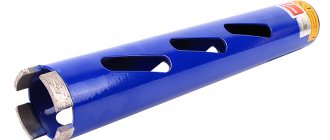
Hole drills
Rice. 6. Annular drill
An annular drill (Fig. 6) is a hollow cylinder with a cutting edge at the end. As a result of drilling, an annular groove is obtained.
Carbide drills
Rice. 7. Twist drill equipped with carbide inserts
The cutting part of any of the above types of drills can be equipped with carbide inserts (Fig. 7). Such drills do not form a separate group in terms of design and nature of the work performed.
Drill sharpening
Cleanliness of drilled holes and high drilling productivity are achieved only if you work with a sharp and correctly sharpened drill.
During the drilling process, the cutting part of the drill wears out and therefore requires systematic restoration of its geometric dimensions. This restoration is carried out by sharpening.
Drills are sharpened on special sharpening machines or manually on abrasive wheels.
Rice. 8. Drill sharpening angles
When sharpening a twist drill for drilling steel, you need to obtain (Fig. 8):
- apex angle (1) equal to 80...140°;
- the angle between the transverse and cutting edges (2) is 55°;
- sharpening the cutting edges (3) with a width of 0.2d at an angle of 70° to each other.
Manual drill sharpening
When sharpening by hand, the drill is held with the left hand by the working part, possibly closer to the cutting part, and with the right hand by the shank. The cutting edge of the drill is pressed against the side surface of the grinding wheel and the drill is rotated with a smooth movement of the right hand, ensuring that the cutting edges take the correct inclination to the axis and the required shape. You should not press the drill too hard, as this will lengthen the sharpening process.
When sharpening, the drill heats up. To avoid loss of hardness, sharpening must be done with cooling. The cutting edges of a properly sharpened drill should be straight. The angle of their inclination to the transverse edge should be equal for a drill with a diameter of up to 15 mm - 50°, over 15 mm - 55°, and the length of the transverse edge should be 10...20 times less than the diameter of the drill.
When manually sharpening, the sharpening of drills is controlled visually.
Sharpening defects
When manually sharpening a drill, the following defects are possible:
1. The length of the cutting edges is not the same: the middle of the transverse edge does not coincide with the axis of the drill.
In this case, the long cutting edge will be more loaded than the short edge and will become dull more quickly. Externally, this is often expressed in the form of chipping near the corner of the long edge. In addition, under the influence of a large load from the edge of the long edge, the drill will be pushed away from the axis of rotation and the hole will be larger in diameter than the diameter of the drill. The deeper the hole, the less accurate it will be. The drill will “beat” and may break.
2. The cutting edges are sharpened at different angles to the drill axis.
In this case, the middle of the transverse edge coincides with the axis of the drill. Since the slope of one cutting edge is greater than the second, the latter will not work. In this case, only one edge will remove chips. Under the influence of a one-sided load on the cutting edge, the drill will move to the side and thereby increase the diameter of the hole.
3. Two defects at the same time.
If, after sharpening the drill, the cutting edges are not equal in length and are inclined to the drill axis at different angles, then the middle of the transverse edge will shift from the drill axis and will rotate around the axis during operation.
Practical drilling techniques
Cutting speed
One of the main issues in drilling technology is the choice of the most advantageous cutting mode, that is, the determination of such a combination of rotation speed and drill feed that ensures maximum productivity.
The rotation speed of a drill is characterized by its number of revolutions per minute. This speed represents the path traveled by the outer points of the drill's cutting edge and is measured in meters per minute.
In the process of cutting materials, the chips, the workpiece and the cutting tool are heated.
The optimal cutting speed when drilling is a speed that ensures high productivity when the drill operates for a sufficiently long time (15...90 minutes) without regrinding.
It has been practically established that at an economical cutting speed, the drill should work without regrinding:
| with drill diameter | 5…20 mm | 15 minutes |
| with drill diameter | 25…35 | 30 minutes |
| with drill diameter | over 40 mm | 90 minutes |
The permissible cutting speed when drilling depends on:
On the quality of the drill material. HSS drills allow higher cutting speeds than carbon steel drills.
On the mechanical properties of the material being processed. The more plastic the material, the more difficult it is to remove chips, the faster the drill heats up and its cutting properties decrease. Therefore, brittle materials can be drilled at higher speeds than tough materials.
From the diameter of the drill. With increasing diameter, the cutting speed can be increased, since a massive drill has greater strength and better removes heat from the cutting edges.
From the drilling depth. The deeper the hole is drilled, the more difficult it is to remove chips, the greater the friction and the higher the heating of the cutting edges. Therefore, all other things being equal, shallow holes can be drilled at a higher speed, and deep holes can be drilled at a lower speed.
From the drill feed rate. The higher the feed, that is, the thicker the chip cross-section, the lower the cutting speed.
On the cooling intensity of the drill. The drill works better at higher cutting speeds and low feeds. If during operation the drill quickly becomes dull at the corners of the cutting edge (at the beginning of the cylindrical part of the drill), this indicates that the cutting speed is too high and should be reduced. If the drill becomes dull or chipped along the cutting edges, this indicates that the feed is too high. Dullness and breakage of the drill most often occur at the end of drilling through holes (when exiting the metal).
To prevent dullness or breakage of the drill during the pass, it is necessary to reduce the feed at the end of drilling.
Cooling and lubrication of the drill. Unfavorable conditions for heat dissipation during drilling necessitate drill cooling. When drilling viscous materials, cooling must be especially abundant.
To cool the drill during operation, use:
- when drilling hard materials - kerosene, turpentine, emulsion;
- when drilling soft materials - soda solution;
- when drilling gray cast iron - kerosene, a stream of compressed air.
By using cooling during drilling, you can increase the cutting speed for steel by 10%, and for cast iron up to 40%, and obtain a cleaner hole surface.
Selecting drill diameter
In practice, depending on the purpose, there are various types of drilling holes, for example through (for passage), blind, reamed, threaded, etc.
In all these cases, drills of different diameters are selected for the same nominal hole diameter.
It should be borne in mind that during the drilling process, the drill develops a hole and makes it slightly larger in diameter. The average values for developing a hole with a drill (the difference between the diameter of the resulting hole and the diameter of the drill) can be taken as follows:
Drill diameter, mm Hole development, mm
| 5 | 0,08 |
| 10 | 0,12 |
| 25 | 0,20 |
| 50 | 0,28 |
| 75 | 0,35 |
To obtain holes with an exact diameter, you should take into account the size of the development and, accordingly, select a drill of a slightly smaller diameter.
There are two ways of drilling: by marking and by jig.
Drilling by marking is used in all repair work, as well as in small-scale and individual production.
Drilling along the jig is carried out without preliminary marking and is used in cases where it is necessary to drill a large number of identical parts.
Checking correct drilling
The hole intended for drilling must be pre-marked and punched both around the circumference and in the center of the hole.
Before starting drilling, it is necessary to firmly secure the drill in the chuck and firmly secure the workpiece in the appropriate fixtures. The workpiece is fixed so that the center of the hole (the recess from the center punch) and the tip of the drill exactly coincide. To check the correct installation of the product, drill a hole to the depth of the drill diameter, and then inspect the resulting circle; if it coincides with the circle marked during marking, this means that the drill was installed correctly and drilling can be continued.
If the circle does not coincide, an appropriate correction is made.
Rice. 9. Kreutzmeisel
To do this, using a cross-piece (Fig. 9) with a semicircular blade, cut a groove on the side where the center of the drill needs to be shifted, punch it, correct the installation of the part, ensuring that the drilled hole completely coincides with the marked circle.
Cause of drill failure
Practice has established the following main causes of drill breakage:
1) encountering a shell on its way, the drill strongly deviates to the side and breaks;
2) if the lower part of the hole in the product is limited not by a horizontal, but by an inclined plane, the drill comes out of the product unevenly, gets stuck in the hole and breaks;
3) when drilling deep holes, when the drilling depth is greater than the cutting part of the drill, the grooves, plunging into the workpiece, become clogged with chips, while the drill becomes very hot, becomes dull and breaks;
4) when the drill leaves the workpiece, that is, at the end of drilling, if the feed has not decreased but remains the same, the drill often breaks;
5) breakage also occurs when working with a blunt drill.
Countersinking
Rice. 10. Countersink
Countersinking is the processing of the exit part of a hole in order to remove burrs and form recesses for the countersunk heads of screws, bolts and screws. The tool used for this purpose is called a countersink (Fig. 10). Countersinks, based on the shape of the cutting part, are divided into conical and cylindrical.
Conical countersinks with apex angles of 30, 60, 90 and 120° are used to remove burrs in the exit part of the hole and to obtain a conical recess in the holes for the supports of the conical heads of screws and rivets.
Cylindrical countersinks with end teeth are used to expand the outlet part of cylindrical holes for flat washers, screw heads, as well as to trim ledges and bosses.
The method of working with countersinks is the same as when drilling holes with a drill, that is, the shank is fixed in the chuck and rotational and translational motion is imparted to the tool.
A source of information:
Makienko N.I. General plumbing course. – M. Higher. school, 1989.
Publication date:
June 28, 2002
Electronic version:
© NiT. Articles, 1997
nt.ru