How is the length of a welding arc measured?
The length of the welding arc is usually divided into long, medium and short.
The choice of its length depends on the thickness of the electrode used
and is calculated as follows:
- Long
– more than 1.5 electrode diameter; - Medium
– from 1 mm to 1.2 electrode diameters; - Short
– from 0.5 mm to 1st electrode diameter.
*
:
Long arc hold
is considered an incorrect process and results in defective seams.
The average length
is used extremely rarely and I generally
advise you to forget about these two types of arc lengths forever
.
To form a beautiful and high-quality seam, only a short arc is used!
The arc may be a little
lengthen to cover an old seam, lock or to melt pores.
Otherwise, it is important to keep the short arc in the required range without exceeding or decreasing the specified length
.
*
As you can see, the difference is significant, and I only increased the length of the arc in the second example by only a few, seemingly insignificant, millimeters.
Based on the practice of teaching manual arc welding to beginners, I concluded that it is precisely the problem of maintaining a short arc throughout the entire length of the seam that is the main one!
Selecting current depending on the diameter of the electrodes
Thin metal, no more than 1 mm thick, is welded with 1 mm electrodes, and the current strength is set to the minimum possible values, in the range of 10-30 A. When welding thicker metal, up to 2 mm, electrodes of a slightly larger diameter are used, 1. 5 or 2 mm. The current strength for welding with these electrodes is set in the range of 30-50 A.
A 3 mm electrode is used to weld metal up to 4 mm, and the current on the inverter is set to 60-120 A. For welding metals over 10 mm thick, much thicker electrodes are already used - 4 and 5 mm. For their normal use, the welding machine must be set to a current of more than 120 A.
How to hold a short arc?
As has already become clear, in order to maintain a stable short arc length, you need to constantly move the electrode forward as it burns.
“Feed” it evenly to the weld pool.
The easiest way to hold a short arc, which by the way is recommended by technologists, is to rest one edge of the electrode (visor) on the surface of the weld pool.
All comes with experience
, because in ordinary life this movement is rarely used, however, in order to achieve it,
you need to remember about frequent mistakes
, which greatly interfere with maintaining a stable arc length.
Mistake number one: fear.
Remembering myself at the beginning of learning welding, moments of wild fear of the process itself clearly pop up in my head. I constantly felt like I was about to be electrocuted or painfully burned by sparks or molten metal.
In order to prevent this, you should simply take care of your clothing
and gloves
- cover all exposed skin and do not worry about sparks, which, if they hit your skin, will make you flinch and throw off the held arc.
Mistake number two: stability
Perhaps the most important criterion for maintaining an even arc length is a stable position of your entire body when welding.
Be sure to take the most comfortable and stable position before welding, run the entire distance with the electrode idle
to make sure your body position is correct.
Hold the handle of the electrode holder with both hands - hold it with one and support it with the other.
If there is a support in front of you, be sure to place the elbow of the hand that is holding your other hand on it.
Wrap the cable around your hand
so that it does not dangle freely in space, does not sway and cannot touch foreign objects.
When welding while standing, it is better not to place your legs narrowly, but to spread them for greater stability.
The principle of manual metal arc welding (MMA)
Shielded metal arc welding, or MMA welding, is a process that melts and joins metals when they are heated by an arc created between a metal-coated electrode and the workpiece. The outer coating of the electrode, called flux, helps create the arc and creates a shielding gas and scale that protects the weld from contaminants. The electrode core provides most of the fill metal during welding.
When the electrode is moved along the part at the correct speed, the metal is deposited in a uniform layer called a weld bead.
The shielded arc welding power source provides constant current (CC) and can supply alternating current (AC) or direct current (DC), depending on the electrode used. The best welding performance is usually obtained using constant current sources.
The power in the welding circuit is determined by voltage and current. Voltage (V) determines the length of the arc between the electrode and the workpiece and depends on the diameter of the electrode. Current is the more significant component that determines the power in the welding circuit and is measured in amperes (A).
The amount of current in amperes required to perform welding depends on the diameter of the electrode, the thickness of the parts being welded and the welding position. Typically, welding small parts requires a smaller electrode and lower current than welding large parts of the same thickness. Thin metal requires less current than thick metal, and a small diameter electrode requires fewer amps than a large diameter electrode.
It is preferable to perform welding work in a horizontal position. However, if it is necessary to weld vertically or overhead, it is advisable to use a lower current than that used for horizontal welding. The best welding results are obtained by maintaining a short arc, moving the electrode at a uniform speed, and feeding the electrode down at a constant speed as it melts.
On the front panel of the welding power source there is a power indicator (white), an overheat or overcurrent indicator (yellow), a current adjustment knob or control controller, adjustment of the positive output voltage (+) and negative output voltage (-). On the rear panel of the welding power source there is an ON/OFF power switch, a cable connector (single phase 50 Hz, 220 V), etc.
A positive connection means that the workpiece is connected to the (+) output on the welding power source, and the electrode holder is connected to the (-) output. A negative connection means that the workpiece is connected to the (-) output on the welding power source, and the electrode holder is connected to the (+) output.
• Connect the part or electrode holder to the outlet (-), without any slack.
• Connect the part or electrode holder to the output (+), without any slack.
• Turn on the power using the ON/OFF switch, and the indicator (white) will light up.
• Now you can start MMA welding.
• To improve welding quality, each ground clamp on the workpiece should be clamped tightly and located as close as possible to the welding site.
Warning!
1) When using some electrodes, the part must be connected to the output (-), and the electrode holder must be connected to the output (+).
2) Generally, for most electrodes, the part should be connected to the (-) output and the electrode holder should be connected to the (+) output.
The overheating or overcurrent indicator starts to light if the overheating protection threshold for this equipment has been reached. If the welding power source is overloaded, overheating occurs. This welding equipment automatically restarts when the temperature inside the welding equipment drops and the indicator goes out.
The welding current is selected depending on the thickness of the workpiece and the diameter of the welding electrode. For MMA equipment, the welding current is l2=(25-47)*D, where D is the electrode diameter equal to 2.0 mm, 2.5 mm, 3.2 mm, 4.0 mm, etc.
It is impossible to learn welding technology simply by reading about it. Experience only comes with practice. The following pages will help the inexperienced welder understand some aspects of welding and gain knowledge. For more detailed information, you should purchase the book “Arc Welding”.
The operator's knowledge of arc welding must go beyond knowledge of the electric arc itself. He must know how to control the arc, and this requires knowledge of the welding circuit and the equipment that provides the electrical current to flow within the arc. The welding circuit begins where the electrode cable is connected to the welding machine and ends where the work cable is connected to the same welding machine. Current flows through the electrode cable to the electrode holder, passing through the electrode and through the arc. On the work side of the arc, current flows through the base metal to the work cable and back to the welding machine; the circuit must be closed for current to flow. To perform welding, the work clamp must be firmly connected to the bare metal of the base. Removal of paint, rust, etc. is required to obtain a good connection. The work clamp should be connected as close as possible to the area that will be welded. The welding chain must not pass through hinges, bearings, electronic components or other devices that could be damaged.
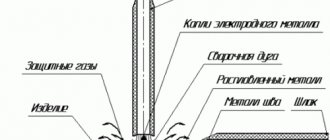
An electric arc is formed between the working area and the end of a thin metal rod, i.e. electrode, which is clamped in a holder that is held by the welder. When holding the end of the electrode at a distance from the welding zone or the base metal being welded, a gap of 1.5-2.0 mm is formed. An electric arc is created in this gap and is held in place or moves across the joint being welded, melting the metal as it moves.
A good welding arc is achieved with experience, a steady hand, good physical condition and good vision; the operator controls the welding arc, and thus the quality of the welding produced.
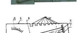
Rice. 1 Welding arc
What happens inside the arc
In Fig.
1 shows the processes that occur in an electric arc. This will give you an idea of what is actually happening during welding.
In the middle of the picture you can see the “arc flow” that an arc creates when there is current flowing in the gap between the end of the electrode and the workpiece. The arc temperature at this point is approximately 3300° C. This is more than enough to melt the base metal. This arc is wide enough and hot enough that it cannot be looked at with unprotected eyes without the risk of painful injury. When observing the arc, you should use highly tinted glasses specially designed for arc welding, these glasses are inserted into a mask worn over the head or into a shield held in the hand.
The arc melts the base metal and actually penetrates it, much like water from a garden hose penetrates the soil. The molten metal forms a weld pool, and the molten zone gradually moves away from the arc as it moves. As the arc moves away from the melt zone, the weld pool cools and hardens. The slag formed at the top of the weld protects it from rapid cooling.
The coated electrode serves more than just to supply current to the arc. The electrode consists of a metal core in the form of a rod, around which a sintered chemical coating is applied. The inner metal rod is melted in the arc and adds droplets of molten metal through the arc into the weld pool. The electrode provides additional filler metal to fill the groove or gap between two pieces of base metal. The coating also melts or burns in the arc. It performs several functions. It makes the arc more stable, provides a shield of smoke-like gas around the arc to prevent oxygen and nitrogen in the air from contacting the molten metal, and provides flux for the weld pool. Flux collects contaminants and forms protective scale. Different types of electrodes differ fundamentally from each other in their coating. By changing the composition of the coating, you can significantly change the performance characteristics of the electrodes. By understanding the differences between coatings, a welder can make the best selection of the best electrode for the job.
When choosing an electrode, the following should be considered:
1. desired weld composition, such as mild steel, stainless steel, low alloy steel;
2. thickness of the welded plate or base metal;
3. The position in which welding will be performed (with the electrode lowered or in another position)
4. condition of the surface of the base metal being welded;
5. the ability to purchase and work with the required electrodes.
Four simple manipulation steps are of paramount importance. Lack of absolute mastery in these four actions renders the welding process meaningless. Mastery of these four steps makes the welding process simple.
Practical definition
A qualified specialist will easily select the optimal connection mode, regardless of the welding mode, MMA or MIG. Beginners often have to turn to reference books.
Manufacturers of welding equipment and consumables provide their products with operating instructions containing recommendations for choosing a mode . Such information should be considered priority.
When working at production sites, there is no opportunity to study technical literature. To select parameters, simple formulas have been developed that allow you to select indicators in a matter of seconds.
The occurrence of an electric arc
The process of formation of a voltaic arc is presented in the following form. At the moment the electrodes come into contact, the passing current releases a large amount of heat at the junction, since there is a large electrical resistance here (Joule’s law).
Thanks to this, the ends of the conductors heat up to a light glow, and after disconnecting the electrodes, the cathode begins to emit electrons, which, flying through the air gap between the electrodes, split the air molecules into positively and negatively charged particles (cations and anions).
As a result, the air becomes electrically conductive.
In welding technology, the greatest application is the discharge between metal electrodes, one electrode being a metal rod, which at the same time serves as a filler material, and the second electrode being the part being welded itself.
The process remains the same as in the case of carbon electrodes, but here a new factor appears. If in a carbon arc the conductors gradually evaporated (burned out), then in a metal arc the electrodes melt very intensively and partially evaporate. Due to the presence of metal vapors between the electrodes, the resistance (electric) of a metal arc is lower than that of a carbon arc.
A carbon discharge burns at an average voltage of 40-60 V, while the voltage of a metal arc averages 18-22 V (with a length of 3 mm).
The correct way to strike an arc
Make sure the work clamp has good electrical contact with the workpiece. Lower the shield and lightly scratch the metal with an electrode; flying sparks will be visible. When scratching, you should raise the electrode by 3 mm, and an arc will appear. Note: If you stop moving the electrode while scratching, it will stick. Note: Most beginners attempt to strike the arc by striking quickly across the plane. As a result, the electrode sticks, or the movements are made so quickly that the arc immediately goes out.
Correct position when welding
The figure shows the correct welding position for right-handed people (for left-handed people it will be the opposite):
a) The electrode holder is held in the right hand.
b) The left hand touches the bottom of the right hand.
c) The left elbow is located on the left side.
Whenever possible, welding is done with both hands. This provides complete control over the movement of the electrode. If possible, welding is done from left to right (right-handed). This allows the welder to see what he is doing. The electrode should be held at a slight angle as shown in the figure.
Rice. 2 Correct position when welding
Arc protection
Examples of protective suits against electric arc
If welding machines use an arc, then many other machines and in addition a person should avoid it. The risk of arcing on equipment depends on several factors:
- frequency of use of the equipment by the employee;
- experience and knowledge of workers dealing with hardware
- equipment wear level;
If a person is not wearing the necessary personal protective suit and falls into the area of effect of the electric arc, the chances of survival decrease quite sharply. The risk of severe burns is extremely high.
Table
Table: degree of exposure to electric arc
What are the possibilities for protection from email? Dougie?
- comply with all necessary safety rules and regulations;
- in case of prolonged use of protective material, frequent washing, the suit should not deteriorate; (it all depends on the model);
- the fabric must have a maximum of 2 seconds of residual combustion;
- you must wear special shoes that have an antistatic effect and also have a suit for protection against electric arcs .
Location and nature of the seam
The influence of electrode speed on the type of seam.
In addition to the characteristics of the welding arc, the following parameters influence the shape and quality of the future weld:
- Preliminary surface preparation, namely edge preparation.
- Electrode movement speed.
- Seam type. It can be one- or two-sided.
- Welding angle of elements.
The horizontal welding method is considered the most comfortable . It allows you to immediately set the optimal parameters of the device, which cannot be said about vertical or ceiling seams.
This is due to the fact that the molten metal, being in a horizontal plane, will not spread. You can immediately start working at high parameters, which will allow you to heat up the metal faster, increasing the connection speed.
Due to the complexity of the location, welding ceiling seams is considered the most difficult job . The work is carried out only at low parameters, which does not always allow for deep heating of the workpiece. Otherwise, the molten metal will quickly drain from the surface under the influence of gravity.
As the surface is gradually heated, the molten metal will be held together under the force of surface tension.
Only qualified welders who are able to control the degree of heating of the parts are allowed to work with ceiling connections. In some cases, an alternative method of working with a ceiling seam is used - instead of reducing the current, they increase the speed of the electrode. As a result, the metal does not have time to acquire strong fluidity, and the speed of work increases.
When chamfering a surface, experienced specialists recommend slightly reducing the current parameters, since the shape of the prepared part provides deeper penetration without increasing the power of the electric arc. At the same time, the speed of movement of the filler material must be increased in order to avoid burn-through of the products.
Basic Concepts
The unit of measurement for electrical current is ampere. According to its properties it happens:
- Constant . In this case, the energy does not change its parameters. Direct welding current is used in semiconductor inverters and welding rectifiers.
- Variable . Characterized by a constant change in the direction of electron movement. This type is used in the power supply of apartment buildings and private houses. The principle of using variable energy is implemented in step-down welding transformers, the primary winding of which is connected to a 220 or 380 V network.
The principle of operation of a transformer.
In addition to the type of welding current, the quality of the future connection is affected by the following parameters:
- Thickness of welded elements.
- The type of metal or alloy to be worked with.
- Parameters and cross-sectional area of the electrode element.
- Welding equipment used and current value.
The last point should be discussed in more detail. The relationship between current strength and amount of heat is direct . The higher the first indicator, the more heat is released when an electric arc burns; accordingly, the base surface heats up faster, increasing productivity.
Based on this, the higher the thickness of the workpiece, the stronger the current must be for complete penetration of the metal.
As the current increases, electrodes with a larger cross-section should be selected, otherwise energy will be wasted irrationally.
The nature of the phenomenon
The arc formation process is as follows:
- The welder touches the metal workpiece with the electrode for a split second.
- At the moment of contact, a short circuit occurs, accompanied by the flow of high current and, as a consequence, a powerful release of heat.
- The metal melts at the point of contact. It becomes viscous and viscous.
- At the moment the consumable is separated from the workpiece, a drop of melt trails behind it.
- Lengthening, it becomes thinner with the formation of the so-called. cervix. At some point, it evaporates and turns into a cloud of charged particles. At the same time, due to the high temperature in this zone, the air or shielding gas is ionized.
- Under the influence of an electric field, negative charge carriers rush to the anode, positive charge carriers - to the cathode. The process of current flow in the plasma begins.
At the moment of contact, a short circuit occurs and the metal at the point of contact melts.
Each stage lasts milliseconds, the discharge occurs almost instantly. The current is then maintained by the emission of electrons at the cathode. On their way to the anode, they ionize gas and metal vapor, increasing the number of free charge carriers.
Modern welding machines are equipped with a high-frequency vibration generator (oscillator). This device allows you to excite the arc in a non-contact manner.
Under what conditions does combustion begin?
An electric welding arc occurs at a current strength of 10 to 1000 A and a potential difference of 15-40 V. In cold air, ignition is difficult because it is weakly ionized. Under such conditions, the workpiece is heated or warm shielding gas is supplied.
Arc Power Supplies
To create a discharge, both direct and alternating voltages are used. In the first case, the weld is of higher quality, and the metal spatters less.
The current from the 220 V network is converted by a transformer, giving an output of 15-40 V.
In order to reduce its dimensions, modern welding machines use a circuit consisting of the following units:
- Input rectifier.
- An inverter is an electronic device with fast-switching transistors controlled by a microcircuit.
- Transformer.
- Output rectifier.
The inverter is the arc power source.
The inverter converts direct current into alternating current with a frequency of up to 80 kHz. This allows not only to reduce the size of the transformer, but also to increase the efficiency of the device.
The source parameters are selected taking into account the method of performing the work. For example, during manual welding, the arc length fluctuates, so you need a device with a steeply falling current-voltage characteristic. Thanks to it, the discharge does not go out when stretched, and when it is shortened, the current does not become too large.
When welding with a consumable electrode, drops of metal flow from it onto the workpiece. At such moments, a short circuit current occurs that exceeds the arc current by 20% -50%. It burns out the formed metal bridge, and the plasma discharge is formed again. These fluctuations occur in short moments of time, so the source must quickly respond to them, stabilizing the potential difference.
We recommend reading: Job Description Items for Electric and Gas Welder
What and how power is determined
Plasma is a conductor with electric current flowing through it. This means that the question of how the power of a welding arc is determined is given the same answer as for any resistor: voltage and amperage. The rate of heat release is equal to the product of these quantities.
The power varies with the current strength, which depends on the length of the arc.
Increasing the potential difference allows you to increase power only within small limits. In addition, the possibility of such adjustment is limited by the size of the electrode.
More often, the power is varied by the current strength, which, in turn, depends on the length of the arc. At the same time, the heating temperature of the metal changes, and with it the speed of work.
Synergetic management
Inverter power supplies allow you to accelerate changes in current parameters up to 1000 A/ms. The high speed of the source contributes to the optimal choice of pulse and pause currents, pulse and pause time, pulse frequency depending on the wire feed speed. This ensures stable transfer of a drop of electrode metal in one pulse.
In modern semi-automatic machines, microprocessor technologies have been introduced to control pulsed welding processes, depending on the steel grade, wire diameter, and type of shielding gas. Such systems are called synergetic.
Thanks to the pre-programming of pulse modes, only two parameters are regulated during welding: welding current and arc length . Synergetic equipment easily adjusts welding modes depending on the grade of steel being welded, the diameter of the electrode wire and the type of shielding gas.
In the synergetic equipment system, optimal welding mode parameters are programmed for various material combinations: carbon steel, stainless steel, aluminum alloys; diameters of solid electrode wire: 1.0; 1.2; 1.6 mm; crater filling time.
For each wire diameter there is a wide range of current mode values, which allows you to weld materials of different thicknesses and in all spatial positions. Synergic systems increase productivity by 20% compared to conventional MIG/MAG welding.
How to choose the right one on the inverter?
The inverter is a product of semiconductor technology. The main advantages of this device are its small dimensions compared to welding transformers and high efficiency, reaching 95%. Modern inverter units are capable of operating in the range from 20 to 500 A. There are a number of useful functions designed to make life easier for the master:
- Fast start;
- Arc Force;
- Anti-stick electrode.
Many devices are equipped with thermal protection devices. Professional models have a dust- and moisture-proof design that can function in difficult conditions.
All this makes the devices an ideal choice for home use. After the purchase, the novice specialist does not know which current to choose for welding with an inverter. To solve this problem, you should follow the manufacturer's recommendations. If they are missing, use reference books.
The welder encounters the main difficulties when working with thin sheet metal, which is very easy to burn through. This process should be approached with extreme caution. For example, to weld a steel sheet 0.8 millimeters thick, the required current will be 35 A. The recommended electrode thickness is no more than 1.8 mm.
When working with electrodes with a diameter of 3-4 mm, which are considered the most popular for household work, to calculate the required ampere characteristics, there is the following formula:
I = d*40 – 10%
Where I is the current strength, and d is the cross-sectional area of the electrode.