A piston internal combustion engine needs to remove crankcase gases, which contain oil vapor. It enters the throttle assembly and combustion chamber and clogs the surface of the throttle valve, pistons, cylinders, and spark plugs. To prevent oil contamination, an oil separator is required. The problem is especially pressing for used cars with considerable mileage.
In order not to expose your car (turbine, air duct, cooler) to the risk of clogging with oil, you will have to buy an oil separator. The disadvantage of a purchased oil separator is that its volume is small, and most standard oil separators cannot be disassembled or repaired. It is more practical to make a homemade oil separator.
Let's try to figure out how to make an oil trap in your garage.
What is an oil separator, its function in a car
First, let's find out what an oil separator is.
An oil separator is a device that separates the oil in compressed gas.
Thanks to the oil trap, oil vapors do not penetrate into the combustion chamber of the engine and reduce the formation of soot.
Important! If the car's mileage approaches 60-80 thousand km, it is recommended to change the oil supply pipe (it often becomes coked and prevents the supply of oil to the turbocharger) together with the turbocharger. If this is not done, the turbine shaft may be damaged and the bearings may fly.
Now let's look at how the oil separator works. There are 2 ways to separate oil from gases:
· Labyrinth method of separation (sedative). With this method, the movement of crankcase gases slows down. Thanks to this, large drops of oil remain on the walls and flow into the crankcase.
· Cyclic separation method. Passing through such an oil separator, the gases undergo rotational motion. Centrifugal forces cause oil droplets to settle on the walls of the oil trap, and then they flow into the crankcase. To prevent crankcase gas turbulence, a labyrinth-type output stabilizer is used. Here the oil is finally separated from the gases.
Note! Modern engines are equipped with a combined type oil separator.
Materials and tools for creating an oil catcher
You can make a crankcase oil trap yourself. As a result, you will receive several benefits at once: it will cost you much less than a purchased one, the crankcase oil trap will be reusable, and you can disassemble and clean it (unlike a disposable purchased one), the device can be made to any size that suits you.
Let's figure out what needs to be prepared to design an oil trap:
- Capacity. You can use a canister from brake fluid, a metal reservoir from a hydraulic booster on a Volga, or plastic sewer pipes.
Note! A metal tank will last longer than a plastic one (plastic often “leads” when exposed to high temperatures).
- 2 hoses.
- 4 hose clamps.
- 4 metal kitchen scourers.
Did you know? If the metal sponges are compacted too tightly, the filter will “suffocate” the escape of gases - as a result, the efficiency of the motor will decrease.
- Fasteners for fixing the oil trap.
- Tube (diameter 14 mm). It can be made from the handle of a hand pump.
If you collect what you need and buy a few things, the oil catcher will cost you about 1,000 rubles.
How to make an oil separator with your own hands
Now familiarize yourself with the design algorithm for making a crankcase gas oil separator with your own hands:
· Disassemble the power steering reservoir. The filter and spring can be discarded. We add everything else (the mesh) to the prepared materials.
· Insert the tube into the empty tank.
We recommend: Causes of misfire errors and how to fix them yourself
Important! The tube must reach the bottom (crankcase gases must sink to the very bottom).
· Loosen the steel wool (they will gain volume) and fill the free space around the tube in the tank with them.
· Place the cotter pin and put the washer on it.
Did you know? A plumbing siphon is a ready-made oil separator, since it is initially filled with sponges. You need to connect the hoses to it and put it in place.
· In the mesh removed from the old tank, make a hole for the inserted tube. Place the mesh in its place in the tank.
· Screw the cap on the tank.
Did you know? If you decide to make an oil trap from sewer plastic pipes, then use the plugs as the bottom and lid.
· The finished tank can be painted on the outside (it will be easier to clean).
· Remove the hose from the throttle body and clean out anything that has accumulated inside. You can clean it with carburetor cleaner.
· Secure the oil separator in its place under the hood.
Important! The oil separator should not dangle, so it can be secured with a rubber or metal loop.
· Connect the hose to the fitting that works as an inlet. If the diameter does not match, you will have to install an adapter.
· Connect the original machine hose to the outlet fitting. All is ready.
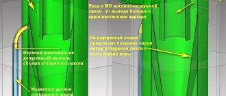
Did you know? You can place a visual hydraulic level outside the oil separator. With its help, you can control the filling of the filter housing with oil and drain it in a timely manner.
Subscribe to our feeds on social networks such as Facebook, Vkontakte, Instagram, Pinterest, Yandex Zen, Twitter and Telegram: all the most interesting automotive events collected in one place.
Depending on the engine design, gas leakage from one engine cylinder into the crankcase space ranges from 10 to 30 l/min. In the operating area of the oil scraper rings, due to the high speeds of piston movement, crankcase gases are enriched with oil particles ranging in size from 0.1 to 2 microns. In addition, the formation of an oil aerosol is facilitated by constant mixing of the oil in the oil bath by a rotating crankshaft.
Crankcase gases contain motor oil, which is suspended in the form of oil mist. Filter modules as part of the lubrication system of modern engines have a special system for separating engine oil from crankcase gases (oil separators).
Existing crankcase ventilation systems allow two options for removing crankcase gases:
- removal of crankcase gases to the atmosphere
- return of crankcase gases to the engine intake manifold
The first method of crankcase ventilation is practiced by few automobile engine manufacturers, and today it does not meet environmental requirements.
The second method reduces the emission of crankcase gases into the environment, but, on the other hand, due to the oil particles contained in the crankcase gases, other problems arise:
- the appearance of deposits on hot engine components, for example on turbocharger blades, which leads to reduced service life
- varnish deposits in the elements of the intake air cooling system
- oiling of the intake tract
- increase in particulate matter in exhaust gases
Therefore, crankcase ventilation systems of a modern internal combustion engine must ensure the separation of oil particles. This is caused by tightening environmental protection requirements, namely reducing the content of particulate matter in exhaust gases.
To separate oil particles from crankcase gases, oil separators of various designs are used. Initially, synthetic fiber was used as an oil separator, which was installed in the form of a filter fabric in the oil separator housing and retained oil particles carried away by the flow of crankcase gases in the engine crankcase ventilation system.
Rice. Oil separator with synthetic separator: 1 – synthetic filter element; 2 – crankcase gases purified from oil; 3 – crankcase gases containing oil particles; 4 – separated oil
The engine oil thus retained was collected at the bottom of the oil separator housing and, through an opening, returned back to the engine oil bath. Structurally, the oil separator is integrated together with the oil filter into the so-called filter block (module).
Rice. Appearance of the filter unit: 1 – oil filter; 2 – oil separator
However, during operation, the properties of the synthetic fiber filter cloth gradually deteriorated, as it became contaminated with resinous substances formed as a result of the inevitable aging of the oil and its oxidation, as well as solid particles, mainly carbon in the form of soot, especially in diesel engines. Contamination of the filter fabric led to an increase in the resistance to the passage of crankcase gases through it, which, in turn, led to a deterioration in the performance of the crankcase ventilation system and dictated the need to replace the oil separator filter element.
We recommend: Restoring the panel after airbag deployment
History of the occurrence of CVKG
At one time, the large company General Motors (GM) thought about the problem of exhaust gas recirculation. During the engine operating cycle, gases are released, which enter the crankcase, increasing the pressure inside the unit and leading to serious malfunctions.
At that time, the Opel automaker still belonged to the GM concern. Companies have decided to install a PCV crankcase ventilation valve on their cars. This valve has a conical shape and operates under the influence of vacuum in the intake manifold. And the membrane of the KVKG valve opens and closes it. At that time, there was a fierce struggle for the ecological state of our planet.
Operating principle and design of crankcase ventilation
This is exactly what the crankcase ventilation diagram of an atmospheric gasoline engine looks like. Gases from the cylinder head enter the intake tract through two pipes, one of which cuts into the system before the throttle, and the second after the damper. This separation of threads is necessary for two reasons:
- At idle and low load, the throttle valve is open to a small angle. The amount of air passing through the filter and entering the throttle space is minimal, and the vacuum is greater behind the throttle. Therefore, excess crankcase gases are sucked into the intake manifold into the throttle space. The amount of gases passing through the channel is regulated by a one-way valve VKG.
- In medium and high load modes, the throttle valve is open to a large angle and does not create obstacles to the passage of air. At the same time, due to an increase in speed, not only the engine’s oxygen consumption increases, but also the amount of gases breaking into the crankcase. Since the vacuum behind and in front of the throttle will be small, both channels are used to effectively remove crankcase gases.
The diagram shows the elements of the crankcase ventilation system of a turbocharged engine, as well as the method of gases entering the sump through the piston rings (No. 5). Components:
- Oil separator. Prevents oil vapor from entering the intake manifold.
- PCV valve that meteres the amount of gases.
- Intercooler. Adding hot exhaust gases reduces the density of the fresh charge, causing engine power to drop. The cooler eliminates this negative factor.
- Turbocharger.
What is a crankcase ventilation system
To reduce the negative impact on the engine life, a ventilation system was developed. It reduces pressure by “sucking out” gases through a system of pipes, hoses and valves. It is shown schematically in the figure.
What does it consist of?
- Pipes, hoses.
- Oil separator.
- Control valve.
In classic VAZ models, crankcase ventilation is simplified; there is no valve.
Scheme of work
- Gases enter the oil separator through hoses, where oil vapors are separated from gases;
- Next they enter the ventilation valve. It is connected to the intake manifold. The vacuum in it “sucks” them back into the intake.
Thus, we get rid of excess pressure.
In domestic cars, the breather plays the role of an oil separator. It is directly connected to the power unit. Oil passing through it settles on its walls. It is directly connected to the intake. One hose is connected to the air filter housing; pumping occurs during engine load. The second hose is connected to the carburetor, below the throttle. It is needed for crankcase ventilation at idle speed of the internal combustion engine.
Oil separator
It happens:
- Tangential.
- Labyrinthine.
In the first case, crankcase gases enter the oil separator housing at an angle. They twist and receive tangential acceleration. Due to centrifugal force, the oil emulsion and vapors remain on the walls of the separator and flow back into the engine sump. The gas flow continues into the valve.
The second type has a labyrinth in its design (it is logical to assume from the name). Crankcase gases passing through it, hitting its walls, flow into the sump.
Crankcase ventilation valve
Necessary for adjusting the intensity of the “suction”. A large vacuum can form in the engine intake manifold at different operating modes. A large vacuum can be created in the crankcase through the ventilation system. The higher it is, the more combustion products of the air-fuel mixture will “break through” the compression rings into the engine volume.
When excess pressure is created, the valve opens, gases are “sucked” into the inlet, and the pressure decreases. When a vacuum is formed, it closes, preventing the creation of a large vacuum. Thus, the extraction of fuel combustion residues, gasoline vapors, etc. is adjusted. from internal combustion engine.
Types of compressor oil separators
The design of compressor oil separators, taking into account their operating principle, is as follows:
- cyclone,
- mesh,
- bubbling,
- inertial.
There are also oil separators for compressors made in a combined version, where several oil separation systems are combined at once.
Cyclone oil separator
This kind of oil separation system uses the principle of centrifugal rotational force. The device is a vessel, with a spiral plate element inside.
The design of the cyclonic action and the cleaning principle for this type of device: 1 - inlet filter; 2 - venture wall; 3 - neck; 4 - oil separator; 5 - cyclone separator
When a mixture of gas and oil, compressed by a compressor, enters the cyclone oil separator, a vortex flow is formed due to spiral plates - elements of the device.
Under the influence of a cyclonic vortex, oil, which has a high specific gravity relative to the gas, is separated and deposited on the wall of the vessel, and then flows into its lower region.
Gas purified from oil leaves the oil separator through the upper pipe. The cleaning efficiency of cyclone devices reaches 80%.
Compressor oil separator
The simplest, from the point of view of mechanical design for a compressor, is a mesh oil separator. The device cleans the gas environment from oil accumulation by filtering the flow with a fine mesh.
The simplest separation and cleaning system is a mesh. In fact, this is an ordinary coarse filter, the efficiency of which is not too high
Moreover, the degree of purification directly depends on the density of the mesh filter. However, too high a density reduces the gas throughput of the grid.
The separation effect is achieved again due to the higher specific gravity of the compressor oil. The mixture of gas and oil meets the grid on its way, changing the direction of movement and speed. As a result, heavy oil particles are retained, while the lighter gaseous medium continues to move.
Meanwhile, the cleaning efficiency of mesh devices is relatively low (no more than 50%). Therefore, this type of compressor separators is classified as coarse filters.
Bubbler oil separators
Bubbling-type oil separators provide compressors with a more refined purification of oil from air or other gaseous medium. The principle of their operation is based on the movement of a compressed gas mixture through a liquid barrier. The cleaning efficiency can reach 80-90%.
A system with a bubbling principle of operation: A - gas inlet; B - gas outlet; C - water drain; D - oil drain; 1 - oil catcher; 2 — drop catcher (demister); 3 - vortex limiter
True, the technological scheme with bubble oil separators must additionally have a system for separating oil from the liquid. This point results in the fact that structurally bubbling oil separators look like a rather complex device and require an appropriate technological approach.
Impact separator
Gravity oil separators, cyclone filters are also called inertial cleaning systems. The principle of operation of such devices is somewhat reminiscent of the operation of a cyclone device.
The device consists of a vessel, inside of which there is a structure resembling a meat grinder screw. The mixture of gas and oil passes from the upper region of the vessel to the lower, changing the direction of movement according to the track of the screw.
The inertial separation (cleaning) system operates on almost the same principle as the cyclone system. Inclined surfaces of the separator are used: 1 - flowing film; 2 - drops
The inertial force separates the oil particles from the gas. They remain on the surface of the helical path, collect into heavier drops and flow into the lower region of the vessel.
Inertial oil separators are quite effective devices - they purify the gas environment by 70-90%. But the use of such systems is limited in relation to the design of compressors. Mostly piston and scroll compressors are equipped with inertial devices.
Combined oil filtration devices
Oil separation mechanisms assembled on the basis of a combined scheme are noted as the most efficient of all existing oil separators (up to 99% purification). But at the same time, combined devices are characterized by complex design and significant maintenance costs.
Combined cleaning systems are distinguished by complex engineering solutions. These are expensive massive installations, usually for industrial purposes.
The combination (combination) of several systems at once in one vessel is, as a rule, impossible. Therefore, the design itself is a massive device consisting of several modules.
Diagnostic methods
The easiest way to check the PCV valve is by yourself. To do this, just blow into the valve from the side of the valve cover. If the air pressure from the reverse side is weak or does not come out at all, the valve is not working properly. Cleaning the crankcase ventilation system with carburetor cleaner should correct the situation. If the valve is blown in both directions, most likely it is stuck in a half-open state, or the rubber membrane is torn.
The degree of contamination and the overall efficiency of the crankcase ventilation is measured in two main ways:
- The crankcase gas pressure is measured at different engine operating modes.
- The volume of gases that the system can pass through itself is measured.
In order not to encounter the consequences of malfunctions of the VKG system, it is worth periodically changing the PCV valve, filter element, and cleaning the centrifugal/labyrinth oil trap.
How to make it yourself
There are many oil traps available on the market today. However, most of them are disposable and expensive. Therefore, many car owners prefer homemade devices that can be cleaned and used for many years.
To make a filter with your own hands you need:
- Take a container. You can use a metal power steering reservoir from Volga as it.
- Place several metal sponges for washing dishes in an empty tank. They should take up the space previously occupied by the filter and springs.
- Cover the container with a built-in mesh and casing.
- Connect the resulting device with hoses to the system on both sides.
A homemade oil catcher will protect turbines, spark plugs and other important car parts from soot.
What is the purpose of and where is the crankcase ventilation valve (CVVV) located?
The crankcase gas cleaning system is the simplest and lightest thing in the engine. And, meanwhile, it needs increased attention from the driver. We are talking about constant care: inspection, cleaning and testing of the system; you also need to pay special attention to the crankcase ventilation valve (CVG). Preventing the release of gases containing the entire periodic table is the main task of this system.
Its device is designed not only to keep the surrounding area clean, but also to reduce the result of gas pressure on internal combustion engine parts to a minimum value.
The crankcase ventilation valve is needed to pass exhaust gases that accumulate in the engine crankcase back into the combustion chambers of the cylinders through the intake manifold. The KVKG is usually located in the intake manifold. There are two types of crankcase ventilation: forced and non-forced.
Oil separator for VAZ 2108, 2109, 21099 engines
The oil separator is part of the crankcase gas removal system on engines 2108, 21081, 21083 of VAZ 2108, 2109, 21099 vehicles.
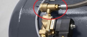
Location of the oil separator on a car engine
The oil separator is located under the valve cover of the engine of VAZ 2108, 2109, 21099 cars and is attached to its inner part using two 10mm socket bolts.
Oil separator device
The oil separator for engines 2108, 21081, 21083 consists of a set (package) of metal plates with many holes. The plates are connected into a package using a cotter pin. The oil separator closes the housing on top.
The oil separator is connected to the fittings of the crankcase gas removal system. Through the thick supply fitting, crankcase gases enter the oil separator, through the thin one they are discharged into the small branch of the exhaust system to the carburetor, through the middle one into the large branch of the system, and enter the engine air filter housing.
Purpose of the oil separator
The oil separator for engines 2108, 21081, 21083 of VAZ 2108, 2109, 21099 vehicles and their modifications is designed to clean crankcase gases from motor oil vapors present in them. This prevents unwanted oil from entering the engine air filter and further into the carburetor.
This is a kind of filter that separates oil from gases.
Operating principle of the oil separator
Under the influence of vacuum, gases from the engine crankcase through the removal system enter under the engine valve cover, where the oil separator is located.
Gases pass through many holes in the oil separator screens, leaving behind the engine oil they have captured from the engine crankcase. The filtered oil flows into the cylinder head and flows through the channels back into the engine crankcase. Purified gases enter either the small branch of the removal system or the large branch, depending on the operating mode of the engine.
Oil separator malfunctions
The main problem with the oil separator is its clogging and contamination. The main factors influencing its contamination are high engine mileage and the use of low-quality engine oil.
A dirty oil separator prevents gases from being effectively removed from the car engine crankcase. As a result, the pressure in it increases, oil begins to ooze from under the engine seals and gaskets and is released through the exhaust system into the air filter housing and carburetor.
In addition, the efficiency of separating oil from gases in the oil separator decreases and contaminated gases enter the engine air filter housing (clogging the filter element) and then into the carburetor (clogging the jets).
Hence such malfunctions as: “failure” when pressing the gas, unstable idling, over-enrichment of the fuel mixture, carbon deposits on the spark plugs, smoke from the muffler, etc.
Notes and additions
— As a temporary (sometimes permanent) measure, many car owners route the hose from the breather not to the valve cover, but under the engine, directing crankcase gases into the atmosphere. Thereby avoiding the negative consequences of clogging the oil separator and crankcase ventilation system. This method is also effective for wear of the engine piston group.
More articles on the crankcase ventilation system of VAZ 2108, 2109, 21099 cars
— Cleaning the oil separator of engines 2108, 21081, 21083
— Cleaning the crankcase ventilation system of VAZ 2108, 2109, 21099 cars
— Oil in the air filter housing, causes
twokarburators.ru
Replacing KVKG BMW G11
Malfunction of the BMW G11 KVKG is a fairly common problem with which people turn to the BMW-E technical center for help. Despite the fact that this car model has only been produced since 2015, some BMW car owners have already managed to repair or replace this unit. And the experienced specialists of our service center happily resolved the malfunction of the crankcase ventilation valve, offering customers the optimal solution to the problem.
The BMW KVKG valve is a small unit that is part of the engine system and ensures timely recirculation of crankcase gases. The latter are a combination of water vapor, gasoline and gas, which are formed during operation of the internal combustion engine and are removed by the valve. Crankcase gases pose a direct danger to the environment and the engine, so you should carefully monitor the serviceability of the CVCG.
If cracked or clogged hoses with combustion products are not repaired in time, or the membrane or valve as a whole is not changed, this will certainly lead to serious engine damage. Pressure is lost when there are too many gases inside the crankcase. In the future, such a seemingly simple breakdown will lead to a leak of crankcase gases and the suction of oil or air mixture.
The BMW-E technical center recommends checking the condition of the unit at least once a year and, if necessary, carrying out a qualified replacement of the BMW KVKG. Our service specializes exclusively in BMW vehicles, and the box is equipped with dealer software. This eliminates any inaccuracies and errors during the repair of new and old cars of the Bavarian company.
How to check KVKG BMW G11 at home
To detect deviations from the norm in the operation of the CVCG, you do not have to go to the service center. The initial inspection and testing of this unit is easy to do at home or in the garage.
- Turn on the G11 engine and open the hood.
- Look for the oil filler neck and unscrew the cap.
- Try to lift the lid slightly, but do not remove it completely.
- If you feel a slight pull of the lid back, then everything is in order with the KVKG.
- However, if you unscrew the lid too quickly or pull it back too strongly, immediately seek the help of a specialist. These are the first signs that the ventilation valve is not working correctly.
Also signs of a breakdown are excessive oil consumption, the appearance of bluish smoke from the exhaust pipe and a smoking engine. If you have one of the listed signs, do not hesitate to go to the BMW-E technical center in order to preserve the integrity of the engine and prevent its destruction due to crankcase gases.
Basic malfunctions of KVKG BMW G11
The cause of malfunction of the BMW KVKG is not so many factors. Conventionally, they can be divided into mechanical and technical factors, however, the procedure for their repair is no different.
Valve failures:
- membrane rupture due to aggressive driving or after an accident;
- cracking or kinking of ventilation/recirculation hoses;
- natural wear of the part;
- hoses become coked by crankcase gases.
At the BMW-E technical center, drivers receive qualified assistance from car mechanics with many years of experience. Our technicians can easily advise the owner of the machine, conduct a quick inspection of the unit and offer optimal replacement units. The service warehouse always has components from the dealer or their durable analogues from reliable suppliers.
Any malfunction of the BMW G11 KVKG is repaired in a sterile box where no dust or dirt gets in. Employees spend no more than a few days on the job and provide a long-term guarantee. The valve will operate without problems after repair or replacement for six months or 10,000 km.
Signs and causes of failure of the BMW M54 KVKG
Failures of the VKV valve manifest themselves not only functionally, but also visually. The main manifestation of a part malfunction is excessive sticking of the cover. This position of the spare part indicates a lack of tightness in the system and deformation of the membrane inside the part. The basic symptoms of a broken VKV valve in BMW M54 cars are:
- Excessively increased consumption of oil fluids and fuel;
- The appearance of uncharacteristic noise in the area where the part is located;
- Reduced engine dynamics and performance;
- Cases of smoke in the engine compartment;
- Uneven operation of the motor;
- Excessive pressure levels.
To check the functionality of the exhaust ventilation valve, it is worth removing the oil filler cap. The lid should fit slightly when opened. If this does not occur and smoke appears, this indicates that the ventilation system is not working properly. Failures in the operation of the VKV valve in BMW M54 cars can occur for the following reasons:
- Complete rupture of the valve membrane element;
- Clogged exhaust gas ventilation hoses;
- Deformation, damage to valve hoses.
Due to these circumstances, the exhaust ventilation valve will absorb oil liquids directly from the engine oil pan. In most cases, this situation can cause the case to become deformed. Air is passed through damaged hoses of the gas ventilation part, which causes a decrease in the performance of the BMW M54.
Clogging of the valve hoses causes the engine oil seals to push through and oil fluids to leak through the valve cover and crankshaft seals.
Consequences of faulty crankcase ventilation
Consequences of high pressure in the crankcase:
- Damage to the rubber seals of the crankshaft and camshaft. The engine will lose oil through squeezed out oil seals. If a sharp decrease in level is not noticed in time, oil starvation can lead to wear of the rubbing pairs and rotation of the liners.
- Turbine failure. After lubricating and cooling the turbocharger parts, the oil should drain by gravity into the pan. If there is a backlash of gases in the crankcase space (a kind of plug), the volume of engine oil pumped through the turbine will sharply decrease. Due to deterioration of heat dissipation, the oil will begin to coke inside the channels and on hot rubbing vapors. The consequence is scuffing on the liners and turbine shaft, which is equivalent to a deep restoration or replacement of the cartridge/turbocharger assembly.
- Squeezing out the dipstick and splashing oil into the engine compartment. In some cases, the dipstick flies out with such force that it leaves a noticeable dent in the hood. In this case, you won’t be able to get rid of it just by washing the engine compartment.
Video: Crankcase ventilation system
Design and principle of operation of the crankcase ventilation valve
The ventilation valve has such a simple device that even a novice car enthusiast can easily learn how to disassemble and clean it.
It consists of:
- Plastic case.
- Lids.
- Inlet and outlet fittings.
- Two cavities.
- Membranes.
- Springs.
The principle of operation of the valve in modern cars
Video about the operating principle of the crankcase ventilation system and valve.
The ventilation valve opens in medium mode, when optimal pressure is created on the membrane. In this position, the valve overcomes the spring pressure. After passing through the oil separator, the gases are cleared of oil droplets, pass into the open valve and complete the cycle, returning back to the combustion chambers, where their combustion is completed.
If we are talking about a non-forced crankcase ventilation system, then the valve almost does not open in idle mode and is closed at high speeds. At high speeds, a lot of gases are released, and hot gases often leak into the intake manifold. In this case, the valve is closed, since there is a risk of ignition of crankcase gases in the crankcase itself.
Where do the gases go if the valve is closed?
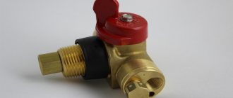
In any case, crankcase gases must be removed and under no circumstances remain inside the system. There is another iron pipe that leads to another valve. This is the so-called “fungus” or pressure reducing valve. When the main valve is closed (and this happens, let me remind you, at high speeds and at idle), the gases pass through this iron pipe directly into the “fungus”.
It also has two states: closed and open. When it is covered, a small calibrated hole inside it opens slightly, which allows the gas mixture to pass through. In this case, the gases escape through a large hole. That is, a system consisting of two valves ensures uninterrupted and reliable crankcase ventilation.
Systems for separating oil from crankcase gases. Oil separators
Depending on the engine design, gas leakage from one engine cylinder into the crankcase space ranges from 10 to 30 l/min. In the operating area of the oil scraper rings, due to the high speeds of piston movement, crankcase gases are enriched with oil particles ranging in size from 0.1 to 2 microns. In addition, the formation of an oil aerosol is facilitated by constant mixing of the oil in the oil bath by a rotating crankshaft.
Crankcase gases contain motor oil, which is suspended in the form of oil mist. Filter modules as part of the lubrication system of modern engines have a special system for separating engine oil from crankcase gases (oil separators).
Existing crankcase ventilation systems allow two options for removing crankcase gases:
- removal of crankcase gases to the atmosphere
- return of crankcase gases to the engine intake manifold
The first method of crankcase ventilation is practiced by few automobile engine manufacturers, and today it does not meet environmental requirements.
The second method reduces the emission of crankcase gases into the environment, but, on the other hand, due to the oil particles contained in the crankcase gases, other problems arise:
- the appearance of deposits on hot engine components, for example on turbocharger blades, which leads to reduced service life
- varnish deposits in the elements of the intake air cooling system
- oiling of the intake tract
- increase in particulate matter in exhaust gases
Therefore, crankcase ventilation systems of a modern internal combustion engine must ensure the separation of oil particles. This is caused by tightening environmental protection requirements, namely reducing the content of particulate matter in exhaust gases.
To separate oil particles from crankcase gases, oil separators of various designs are used. Initially, synthetic fiber was used as an oil separator, which was installed in the form of a filter fabric in the oil separator housing and retained oil particles carried away by the flow of crankcase gases in the engine crankcase ventilation system.
Rice. Oil separator with synthetic separator: 1 – synthetic filter element; 2 – crankcase gases purified from oil; 3 – crankcase gases containing oil particles; 4 – separated oil
The engine oil thus retained was collected at the bottom of the oil separator housing and, through an opening, returned back to the engine oil bath. Structurally, the oil separator is integrated together with the oil filter into the so-called filter block (module).
Rice. Appearance of the filter unit: 1 – oil filter; 2 – oil separator
However, during operation, the properties of the synthetic fiber filter cloth gradually deteriorated, as it became contaminated with resinous substances formed as a result of the inevitable aging of the oil and its oxidation, as well as solid particles, mainly carbon in the form of soot, especially in diesel engines. Contamination of the filter fabric led to an increase in the resistance to the passage of crankcase gases through it, which, in turn, led to a deterioration in the performance of the crankcase ventilation system and dictated the need to replace the oil separator filter element.
Cyclone oil separators
To get rid of the shortcomings of synthetic fiber filter fabric, cyclonic oil separators began to be used in the latest models of modern cars.
Rice. Operating principle of the engine crankcase ventilation system with a cyclone oil separator: 1 – cyclone oil separator; 2 – pressure regulation valve; 3 – charge air cooler; 4 – turbocharger; 5 – gases breaking through the piston rings
Crankcase gases are supplied through a channel inside the engine into a cyclone oil separator. The cyclone oil separator causes the air to rotate. Due to the resulting centrifugal force, the oil mist hits the wall of the oil separator. Drops of oil form there, which flow through a channel in the crankcase into the oil pan. The air, cleared of oil mist, is supplied to the air intake duct through the pressure control valve.
The cyclone oil separator is equipped with a special valve that limits the vacuum in the engine crankcase, since a strong vacuum can damage the engine oil seals and other rubber seals.
Rice. Diagram of operation of the cyclone oil separator pressure control valve: 1 – crankcase gas supply pipeline; 2 – air intake pipeline; 3 – membrane; 4 – compression spring; a – open position of the valve; b – valve closed position
The pressure control valve is located in the cover of the cyclone oil separator. It consists of a diaphragm and a compression spring and regulates the pressure when air is removed from the crankcase. The pressure control valve closes when there is a strong vacuum in the intake channel. When there is a slight vacuum in the intake channel, it opens by the force of a compression spring.
ustroistvo-avtomobilya.ru
What are valve malfunctions?
The presence of a malfunction can be determined by its characteristic symptoms.
- Oil splashing and increased oil consumption.
- Filter dirty.
- The engine does not start at full power or you can hear a slight whine from the engine.
Basic malfunctions.
- The valve and membrane are dirty.
- Exhaust openings and pipes are dirty.
- The membrane has worn out and flattened.
Crankcase gases are usually not completely released from the oil in the oil purifier. All components of the system - membranes, pipes, valves - become dirty and clogged with oil soot. If the driver does not take the time to clean them, the crankcase pressure increases. A strong smell, burning and soot appears when the engine is running. You may notice that oil consumption increases.
When a valve fails, oil pressure increases and is forced past the seals and gaskets. Valve wear is also characterized by a decrease in engine power. In this case, the pressure in the exhaust system increases or even the operation of the internal combustion engine stops completely. If the damaged valve is not completely blocked by the membrane, then oxygen entering the combustion chamber will help the engine fail.
Oil washer. What, why, and do you need
In general, it is correct to call it an “oil catcher”. But you must admit, it’s much more brutal to casually throw out “Yes, I’m thinking about installing an oil sump.” “But in order to install it, you need to understand what it is, where it is placed and why, in fact, it is needed. Today we'll figure it out. And first, a little theory.
Where does the oil in the intake come from?
Let me start by saying that in this article I have already explained in detail and in simple words what crankcase ventilation
(VKG) and why it is needed. It also describes step by step why oil can burn due to a clogged system and how to fix it. But constant topping up to the level is only an external manifestation of the disease. It becomes much more fun when the speed starts to fluctuate, errors in mixture formation and throttle appear, and traction deteriorates. And all this because the oil flying into the intake throws everything it passes through in its path: the throttle itself, the idle air regulator, sometimes even the mass air flow sensor. Well, I’m not talking about carbon deposits on valves and pistons, due to the constant bathing in oil mist.
Thus, we already know (those who don’t know, follow the links above and find out) that the root cause of “Shrovetide” in the intake tract is, as a rule, inadequate ventilation. Why she can’t cope is, again, explained in my other articles, but today we’re talking about dealing with the consequences.
So what should we do?
Well, everything is transparent here. No matter how anyone makes excuses, a healthy engine won’t throw spoonfuls of oil into the intake
.
And if you’re too lazy to start repairing the engine, but the oil pumping is already bad, we’ll treat it with poultices. And for this, caring manufacturers of various tuning
have long come up with special fo-yu!
As you may have guessed, we are talking about a device called an oil trap
(the notorious oil washer).
By the way, do not confuse it with the membrane oil separator
of the same ventilation system. So, the name fully reflects the simple-as-a-log essence of the miracle device: to catch the liquid component from the mixture splashing with oil, accumulating it in a reservoir. If very schematically, then take a ventilation tube (the so-called breather), pull it out of the inlet pipe and insert it into the oil trap. Profit! And then there are possible options.
A)
The outlet from the oil trap (MU) is inserted back into the inlet. That is, with this scheme, the MU serves as a separator embedded in the line, separating the liquid and then returning crankcase gases to the intake tract (as it was from the factory). Only without oil. The most correct scheme. Accordingly, almost no one does this.
b)
The exit from the MU is not inserted anywhere, but goes out stupidly outside, into the atmosphere. The hole in the inlet pipe is plugged with a plug. Even a plastic bottle can be used as an oil separator body. A method for those who “I’ve been working on cars for 40 years!” and the right guys on the humiliated Devyatyny with a Chinese turbine.
Why is option "a" better?
There are a couple of objective reasons for this.
- The crankcase gases are also drawn out by the vacuum in the intake, whereas in the second option they come out only under pressure in the crankcase itself. Actually, this is how the engineers intended it: there should always be a vacuum in the ventilation system
. Otherwise, its effectiveness decreases. Well, that is, if the cart is not only pushed from behind, but also additionally pulled from the front, it will move much easier. The analogy is clear. - An unforgettable and chronic exhaust smell in the cabin is sure to await users of the second option. Of course, many people install “vapor suppressors” in the form of fuel filters and other gadgets at the atmospheric outlet of such an oil trap, but all these are half-measures and help little.
In general, there are a lot of both ready-made purchased options and ideas for individual implementation. Right down to almost computerized circuits with controlled valves, automatic draining of accumulated oil back into the crankcase and a function for preparing borscht for the driver.
A small digression. There is one exception, when an oil trap is required as standard. This is motorsport. For example, the same forged pistons that any schoolchild who is saving up for his first “seven” (not BMW) dreams of have a small nuance. In the form of hellish thermal expansion during operation. This means that they need to be inserted into the cylinders with great anticipation in terms of the “ring/cylinder wall” gaps. Like a pencil in a glass.