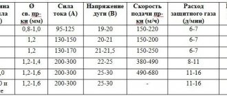
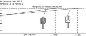
Home » Building a house » Categories » Electrics
Alexander Korovaev 09.29.2019
1141 View
Electricity is not something to joke about, but you shouldn’t be afraid of it either. If you correctly understand the structure of electrical networks, at least at the initial level, then nothing bad will happen.
In order to use electricity safely, the average person needs to know a few easy-to-understand things, which include the concepts of phase, zero and grounding.
Many people know what a phase is, but few know what zero and ground are, what is the fundamental difference between these concepts.
What are “zero” and “ground” according to the PUE?
What we are used to calling “zero” and “ground” in the PUE is called the zero working conductor ( N ) and the zero protective conductor ( PE ). Here is how they are interpreted in the regulatory document:
1.7.17. A protective conductor (PE) in electrical installations is a conductor used to protect people and animals from electric shock. In electrical installations up to 1 kV, the protective conductor connected to the solidly grounded neutral of the generator or transformer is called the neutral protective conductor.
1.7.18.a The neutral working conductor (N) in electrical installations up to 1 kV is the conductor used to power electrical receivers, connected to a solidly grounded neutral of a generator or transformer in three-phase current networks, to a solidly grounded terminal of a single-phase current source, to a solidly grounded source point in three-wire networks direct current.
From these formulations it is clear that the protective neutral conductor is necessary to protect against electric shock. That is, electrical equipment must be grounded to it, for example, a washing machine, boiler, boiler, etc. At the same time, the working neutral conductor is necessary to power the equipment, that is, current will flow through it.
In some cases, it is allowed to use “zero” (PE) as “ground”, as specified in PUE 1.7.18.b. In this case, the wire becomes a combined conductor, which combines the functions of the zero protective and zero working conductors. It will be called PEN. However, there is one nuance that is important to know.
The fact is that according to PUE 1.7.83 “There should be no disconnecting devices or fuses in the circuit of grounding and neutral protective conductors.” That is, the neutral protective conductor (“ground”) must run continuously from the panel to the outlet or lighting fixture. If we, for example, ground the ground to zero, then the "path" is interrupted by removing the plug from the socket. And if a breakdown occurs, the body of the remaining equipment grounded to this wire will be energized.
Further in the same paragraph it is said: “In the circuit of neutral working conductors, if they simultaneously serve for grounding purposes, it is allowed to use switches that, simultaneously with disconnecting the neutral working conductors, disconnect all live wires.” It follows from this that “zero” can be used as “ground” if, when it is turned off, all live steel conductors are also turned off. It is quite difficult to do this in an apartment environment.
- Technologies
Why is the voltage in the networks 110 V in the USA, and 220 V in Russia?
How to use zero as a ground
If there is no grounding in the old apartment, then you can make it using zero for these purposes. To do this, the zero in the electrical panel of the house must be divided into “protective” and “working”. For these purposes, an additional busbar for PE conductors is installed in the electrical panel, connected by a jumper to zero.
However, there is an important rule! Thus, electrical appliances can only be connected to the protective circuit through a special contact. It is strictly forbidden to use the usual grounding contact on electrical appliances for these purposes, since a break in the zero will lead to the fact that the metal parts of the electrical appliances will be under dangerous voltage.
In this case, the best safety option would be to install an RCD - a residual current device. In the event of a current leak, the RCD will detect a dangerous potential and automatically disconnect the electrical appliance from the 220 Volt network.
The operating principle of the residual current device is based on the following:
- Roughly speaking, the RCD controls how much voltage has gone through the phase wire and how much has returned through the neutral wire;
- If there was no “return”, that is, there was a current leak, then the RCD will see this and instantly operate (turn off the electrical appliance).
There are residual current devices of various ratings for installation on individual electrical appliances, for example, in the bathroom, as well as on the entire house or apartment. This is very important to consider when choosing an RCD in order to protect yourself as much as possible from dangerous voltage leaks.
How should grounding be carried out in a three-wire network?
At the moment, in most new buildings, a three-wire network is installed, in which there is a phase, neutral and grounding (yellow-green wire). “Zero” and “ground” are connected in the shield to one grounding bus, but not under a common contact clamp ( PUE 7.1.36 ). The ground is then connected to each outlet in one continuous wire. Most modern electrical equipment already has a third grounding pin on the plug, which provides grounding to the chassis when it is plugged into an outlet.
Definition of grounding
Grounding is the deliberate connection of exposed parts of electrical equipment that are energized to a special ground tap, busbar or other protective equipment. This could be reinforcement in the ground, part of an electrical installation or other devices. This approach, according to the PUE, is a mandatory measure of deliberate protection of both residential and non-residential assets. This is also stated in the rules and requirements of GOST 12.1.030-81 SSBT (electrical safety and system of occupational safety standards).
Photo - diagram
Almost every modern house has a TN-CS or TN-S grounding scheme. But in old buildings there is often no grounding at all, so apartment owners in such buildings have to organize the ground on their own. This system is called TN-C. This is done by connecting the tap to the grounding loop, which can be located directly in the ground near the building or near the transformer booth.
Theoretically, such a wiring upgrade could be organized by a special installation company, but this is rarely practiced. More often, ground is supplied to the panel on the floor (in an apartment building), and the remaining wires are connected to it.
- If a phase hits an open metal tap of any electrical device, then voltage appears in it. The same happens if, for example, the cable insulation is broken. The human body is an excellent conductor of current; if you touch such a tap, you will receive a strong electric shock. Grounding will help avoid this;
- Stray currents go into the grounding conductor, this guarantees life protection;
- Particularly dangerous is the voltage that reaches heating radiators. In this case, all batteries in the house become current conductors. But if the ground is installed, then all the voltage will go through the conductor.
Photo - land version
If it is not possible to establish a full grounding circuit, then other methods are used. For example, it is now very common to connect portable grounding pins (portable busbars). Their operation is no different from a standard stationary outlet, but at the same time they are much more practical in their functionality.
Photo - portable splint
Conclusion
The main distinguishing feature of “zero” and “ground” is their purpose. “Zero” together with the phase is intended to power electrical appliances, and “ground” is to protect people and animals from electric shock if a breakdown occurs. The working “zero” can be used as a “ground” if the conditions of PUE 1.7.83 are not violated. We recommend laying the wiring immediately with a grounding conductor, which eliminates the need to use the “zero” for other purposes.
Test your electrical knowledge:
- Why is there 220 V between phase and zero, and 380 V between phases?
- Why is the voltage in the networks 110 V in the USA, and 220 V in Russia?
Safety precautions during inspection
When working with electrical wires, you must follow the safety rules:
- Check voltage using instruments, and do not rely only on color markings. There are situations when electricians, through inattention or ignorance, installed electrical wiring without observing generally accepted connection conditions based on the colors of the wires.
- Before starting work, visually check the serviceability and integrity of the cable.
- Do not allow wires to come into contact with wet, hot, oily objects or surfaces.
- In factory-made complete switchgears, check the presence or absence of voltage using built-in stationary voltage indicators.
- Testing in electrical installations with a voltage of 35 kW is carried out using an insulating rod by contacting it with live parts. The presence of crackling and sparking indicates the presence of tension.
- Do not touch exposed electrical wiring.
- It is allowed to work with wiring from a stepladder if the height of the cables does not exceed 3 m from the floor. It is prohibited to place ladders on various supports (boxes, barrels, etc.).
Electrical network structure, main elements
It is known from a school physics course that if you rotate a permanent magnet around a winding on a coil in wires, an EMF (electromotive force) arises, which moves charged particles along the wires. This example explains well what phase and zero are in electricity.
An example of obtaining EMF and current in a metal conductor frame
Based on this principle, electrical energy generators are created on an industrial scale: it can be a nuclear, hydro, or thermal power plant. Sometimes, to provide temporary power supply in emergencies, diesel, gas or gasoline generators are used at facilities that consume little power. There have been cases in history when nuclear submarines and icebreakers supplied electricity to entire populated areas.
Scheme of the transmission and conversion line for electricity
From the generators of power plants, electricity is transmitted through the conductive conductors of cables or power lines (overhead power lines) with a high voltage of 6-10 kV to transformer substations that step down to 04 kV. From the low side of the transformer, energy is supplied to the distribution boards of industrial facilities, residential buildings and apartments in multi-storey buildings. We can say that a phase in electrical engineering is a transport system for transmitting electricity. Along these conductive wires of a cable or power line, charged particles move at the speed of light to the load.
It is in the cable that the conductors are separated as phase, neutral, and ground. Industrial power plants transmit energy to consumers via four- or five-core cables.
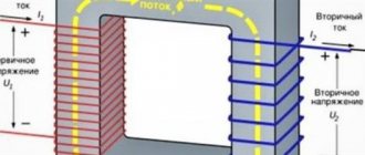
Connecting the generator windings to a three-phase network
Currents are taken from three separate windings of the generator and flow through different wires to the load. In electrical engineering, these conductors are called phases. The fourth core is the neutral wire, which is ultimately connected to the grounding bus in distribution boards, transformer substations and generators. Such circuits are called circuits with a grounded neutral. A phase in electricity is a conductive part along which charged particles move from the generator to the load. To understand what zero is, or why a neutral core is needed, you can compare electric current with the flow of water.
Disconnecting wires in the panel
This method can be used in any power supply circuit, and to implement it, a voltage indicator with two probes, even the old Soviet PIN-90, is sufficient:
- 1. the input circuit breaker in the electrical panel is turned off;
- 2. the wires are disconnected from the grounding bus;
- 3. the circuit breaker turns on;
- 4. In the distribution or installation box, the indicator searches for two conductors, the voltage between which will be 220V.
The remaining conductor is the grounding conductor.
Video description
Earth instead of zero.
TN
Exposed conductive parts are non-insulated areas of electrical installations that can be touched. During normal operation, no voltage is supplied to these areas of household electrical appliances. However, everything will be the other way around: if the insulation is destroyed, potential will appear on the body.
The causes of damage are mainly related to specific factors:
- aging technology;
- physical destruction;
- long service life at high speeds;
- accumulated dirt;
- humidity on the coating located near the body;
- climate influence;
- defect caused by the manufacturer.
How phase wires are painted
When working with wiring, phase wires pose the greatest danger. Touching the phase, under certain circumstances, can become lethal, which is probably why bright colors were chosen for them. In general, the colors of electrical wires allow you to quickly determine which of a bunch of wires are the most dangerous and work with them very carefully.
Coloring of phase wires
Most often, phase conductors are red or black, but other colors are also found: brown, lilac, orange, pink, purple, white, gray. Phases can be painted in all these colors. It will be easier to deal with them if you exclude the neutral wire and ground.
In the diagrams, phase wires are designated by the Latin (English) letter L. If there are several phases, a numerical designation is added to the letter: L1, L2, L3 for a three-phase 380 V network. In another version, the first phase is designated by the letter A, the second by B, and the third by C .
Ground wire color
By modern standards, the ground conductor is yellow-green. It usually looks like yellow insulation with one or two longitudinal bright green stripes. But there are also transverse yellow-green stripes in color.
Grounding may be this color
In some cases, the cable may only have yellow or bright green conductors. In this case, the “earth” has exactly this color. It is displayed in the same colors on diagrams - most often bright green, but it can also be yellow. Signed on circuit diagrams or on ground equipment in Latin (English) letters PE. The contacts to which the “ground” wire must be connected are also marked.
Sometimes professionals call the grounding wire “neutral protective”, but do not be confused. This is an earthen one, and it is protective because it reduces the risk of electric shock.
What color is the neutral wire?
Zero or neutral is blue or light blue, sometimes blue with a white stripe. Other colors are not used in electrical engineering to indicate zero. It will be like this in any cable: three-core, five-core or with a large number of conductors.
What color is the neutral wire? Blue or cyan
“Zero” is usually drawn in blue on diagrams and signed with the Latin letter N. Experts call it a working zero, since, unlike grounding, it participates in the formation of the power supply circuit. When reading a diagram, it is often defined as "minus", while the phase is considered "plus".
How to check the correctness of marking and wiring
Wire colors in electrical engineering are designed to speed up the identification of conductors, but relying only on colors is dangerous - they could be connected incorrectly. Therefore, before starting work, you should make sure that you have correctly identified their affiliation.
Take a multimeter and/or an indicator screwdriver. It’s easy to work with a screwdriver: when you touch a phase, the LED built into the housing lights up. So it will be easy to identify phase conductors. If the cable is two-wire, there are no problems - the second conductor is zero. But if the wire is three-wire, you will need a multimeter or tester - with their help we will determine which of the remaining two is phase and which is zero.
Determining the phase wire using an indicator screwdriver
We set the switch on the device so that the selected jackal is more than 220 V. Then we take two probes, hold them by the plastic handles, carefully touch the metal rod of one probe to the found phase wire, the second to the supposed zero. The screen should display 220 V or the current voltage. In fact, it may be significantly lower - this is our reality.
If 220 V or a little more is displayed, this is zero, and the other wire is presumably “ground”. If the value is less, we continue checking. With one probe we again touch the phase, with the second - to the intended grounding. If the instrument readings are lower than during the first measurement, there is “ground” in front of you and it should be green. If the readings turn out to be higher, it means that somewhere there was a mistake with “zero” in front of you. In such a situation, there are two options: look for exactly where the wires were connected incorrectly (preferable) or simply move on, remembering or noting the existing position.
So, remember that when testing a phase-zero pair, the multimeter readings are always higher than when testing a phase-ground pair.
And, in conclusion, let me give you some advice: when laying wiring and connecting wires, always connect conductors of the same color, do not confuse them. This can lead to disastrous results - at best, equipment failure, but there may also be injuries and fires.
Clamp meter
If all devices are connected correctly, and you need to find a grounding wire in the junction box, for example, to connect an additional line, you can use a current clamp. This device allows you to measure the current flowing through a wire without cutting it.
To do this, you need to turn on the electrical appliances connected after the box and measure the current in the wires. Since power is supplied through the neutral and phase conductors, there will be no current in the grounding wire.
Video description
Grounding instead of zero in the socket. What will happen.
Therefore, deal with the absence of a “zero” in your electrical wiring. If the “working 0” going to the electrical outlet is damaged, find the location of the damage to the neutral circuit.
Instead of a damaged “zero”, you can use a ground wire. To do this, a new marking must be made:
- on the zero line;
- in sockets;
- in the electrical panel.
The oven and dishwasher must be connected to different groups. Each line must be equipped with a separate protective circuit breaker. An RCD can be installed as a common one for the entire electrical circuit.
The grounding conductor is also the same for everyone; it can be taken from another line.
Wire color coding
The color of the cable sheath is not chosen arbitrarily, but according to certain rules specified in GOST 31947-2012 clause 5.2.1.6. If you are confident that these rules were followed during installation, the easiest way to find out the purpose of the conductor is to determine it by the color of the insulation:
- brown, black or gray - phase (L);
- blue - neutral (N);
- longitudinal yellow and green stripes - grounding (PE).
This method is applicable for electrical wiring completed after 2012.
Let's analyze the situation with diagrams
From the point of view of the flow of electric current, there is no difference between grounding and grounding. The neutral wire in any case has electrical contact with physical ground.
Accordingly, when a phase is shorted to the housing, the same short circuit will occur and the circuit breaker will turn off. Of course, (subject to proper connection: the socket must have a third ground contact, just like an electrical appliance. For this reason, electricians, violating the requirements of the Electrical Installation Rules, often separate the ground bus from the zero contact of the input panel.
Let's imagine a situation where the neutral wire is broken for some reason:
- loss of contact due to corrosion (in old high-rise buildings this is a working situation);
- mechanical rupture of the cable due to repair work with violations of technology (unfortunately, also not uncommon);
- unauthorized intervention by a home-grown “electrician”;
- accident at the substation (only the zero bus may be disconnected).
In the diagram it looks like this:
When organizing protective grounding, the electrical circuit between the physical “ground” and the grounding contact of the electrical appliance is broken. The installation becomes defenseless. In addition, a free phase without a load can create a potential equal to the input voltage at the nearest substation. Typically this is 600 volts. You can imagine the damage that will be caused to the electrical equipment that is turned on at this moment. In this case, there is no current leakage to the physical ground, and the circuit breaker will not trip.
Imagine that at this moment you simultaneously touch a phase (a breakdown on the body of an electrical installation) and a metal object that has a physical connection with the ground (a water tap or a heating radiator). You can get electrocuted at 600 volts.
Now let's see what the difference is between grounding and neutralizing (in our diagram). If the zero bus breaks, the power to all electrical installations in this circuit will simply disappear. There will be no electric shock under any circumstances: the electrical circuit between the physical ground and the grounding contact of electrical appliances is not broken. We have already preserved our health. Now let's see what happens to electrical installations. The maximum damage is a burnt-out incandescent lamp closest to the input panel. Moreover, trouble will only occur if the voltage on the phase wire increases. The current strength will increase (according to Ohm's law), the circuit breaker will work, and perhaps other electrical appliances will not be affected.
It is for this reason that the PUE strictly prescribes: protective grounding and grounding of electrical installations must be organized independently of each other, using different lines.
For reference: Wire color coding is usually used:
- The phase is brown or white.
- The working zero is blue.
- Protective grounding is a yellow-green shell.
If you have a modern home, then grounding and grounding are carried out in accordance with the Electrical Installation Rules. This can be easily checked by looking at the input cable in the panel. In addition, you can check the correct connection yourself.
Two connection schemes
The same zero break, but the consequences are so different
To understand the role of “Zero” and “Earth”, you need to delve a little into the essence of the methods of delivering electricity to end consumers and the differences between the latter.
It should be mentioned that electrical systems can be linear and phase. Linear ones are used in the industrial field of activity, where increased power is required (380V), phase ones exist for use in everyday life (220V). In both cases, the connection diagrams use three wires. Only for linear (380) there is a phase in each of the three wires, and in the household version (220V) there is Phase, Zero and Ground.
For security, each system uses its own connection schemes. We will not consider industrial networks, but household networks should be studied; two schemes are used here:
- TT – full grounding
- TN-CS – joint connection of ground and zero, after the power consumer
Connection diagrams used: 1. To zero, 2. To ground
To make it more clear, let's decipher the abbreviation:
- T – earth
- N – neutral
- S - separate, independent
- C – combine
- L – phase
- PE – protective
- PEN - united
These two schemes are used, but one more existing scheme, TN-C, should be pointed out - this is an old, but still valid system used in most “old” houses, which has the abbreviation PEN.
In it, Zero and Earth are combined (PEN) throughout. Such networks are not entirely safe, especially for electrical appliances. They were installed in Soviet times, few household appliances were used, and therefore the designers did not see the point in unnecessary spending on electrical wiring for the sake of a couple of dozen televisions (the loads were small) - 30% savings! At industrial enterprises, grounding was done separately.
Possible faults in the electrical network and the operation of protective devices when they occur
Users are presented with a description of the most common problems that arise during the operation of electrical appliances. For the convenience of considering this issue, the information is summarized in the table:
| No. | Malfunctions | Protection |
| 1. | Damage to electrical insulation in the wall or ceiling | Grounding (grounding) RCD |
| 2. | Current leakage into the housing due to humidity, contact failure, or wire chafing | -/-/-, RCD |
| 3. | Short circuit | -/-/-, Automatic switch |
| 4. | Failure of the heating element or motor (phase breakdown on the housing, including through water) | -/-/-, VA |
| 5. | Action through the body of the device of current from the capacitors of the electronics system | -/-/-, RCD |
With proper protective grounding (grounding) and the use of additional protective equipment, these factors will not cause significant harm to property or human health.
Where did zero come from and what does it look like?
If we consider planet Earth from the point of view of electrical engineering, then it is a spherical capacitor. It has three elements:
- The earth's surface has a negative potential.
- The ionosphere is a layer of the atmosphere that receives and partially scatters solar radiation. She has positive potential.
- A gas atmosphere that has dielectric properties and acts as a lining.
The potential difference between the plates of this global capacitor is 300 thousand volts. It decreases as it approaches the surface. So, at an altitude of 100 meters its value is 10 thousand volts.
Why do we consider the Earth's potential to be zero, because in fact it has a completely material value, albeit with a negative sign? This question is worth asking the scientists of the 18th or 19th centuries who laid the foundations of electrical engineering.
For example, the English physicist Michael Faraday. So it was more convenient for them to measure the strength of the electromagnetic field - taking the Earth as the reference point (zero). This technique is used in many branches of science. For example, in thermodynamics. In it, the temperature at which the movement of electrons in the atomic structure of any substance stops is taken as absolute zero.
This is the so-called Kelvin scale, which differs from another temperature measurement system - it was proposed by Anders Celsius - by 273 degrees with a minus sign.
So, electric zero is a conventional concept that is used in relation to any object with a negative potential. It can be obtained in three ways:
- Having joined the earth's firmament, which is why the concept of “grounding” came about.
- The crystal lattice of all metals has a negative charge of varying magnitude, which determines the degree of their electrochemical activity. Therefore, it is enough to attach to a metal object of large mass and volume. The last two conditions are mandatory, since the body must have an electrical capacity comparable to that of the Earth. This is called working ground.
- By connecting conductors with alternating current flowing through them so that at a common point the sum of their vector addition is equal to zero (the so-called star circuit), which is why it was called neutral. This is the basis of a technique called zeroing in electrical engineering.
Differential current (RCD, difavtomat)
Another option for distinguishing zero from grounding involves the presence of differential protection in the panel with a setting of 10-30 mA. These devices compare the current flowing through the neutral and phase wires and turn off if the equality is violated.
To search for a grounding conductor, an electrical appliance, for example, a lamp with a power of more than 10 W, must be connected to the cable being tested. If the protection is triggered when turned on, it means that grounding is used instead of the neutral wire.
| Important! Before starting work, you must check the serviceability of the RCD by pressing the “TEST” button. |
Basic concepts.
Current strength is a scalar physical quantity equal to the ratio of the charge passing through the conductor to the time during which this charge passed.
where
I is the current strength, q is the amount of charge (amount of electricity), t is the charge transit time.
Current density is a vector physical quantity equal to the ratio of the current strength to the cross-sectional area of the conductor.
where
j
is
the current density
,
S
is
the cross-sectional area of the conductor.
The direction of the current density vector coincides with the direction of motion of positively charged particles.
Voltage
-
a scalar physical quantity equal to the ratio of the total work of Coulomb and external forces when moving a positive charge in an area to the value of this charge.
where A is the total work of external and Coulomb forces, q is the electric charge.
Electrical resistance is a physical quantity that characterizes the electrical properties of a section of a circuit.
where ρ is the resistivity of the conductor, l is the length of the conductor section, S is the cross-sectional area of the conductor.
Conductivity is the reciprocal of resistance
where G is conductivity.
What is the danger of damaging the neutral wire?
Overheating of the neutral wires due to poor contact.
Zero is damaged due to mechanical stress, short circuits, poor-quality connections or as a result of old wiring. Neutral break:
- PEN conductor in the power cable - there is only one ground loop left, which is not visually noticeable;
- combustion of a conductor in the switchboard - phase conductors become distorted, the voltage increases to 380 V;
- there is a break in the apartment panel - the second phase remains in the sockets, household appliances are not powered from them.