Types of commutator motors
At least two types of commutator motors are known. The first includes devices with an armature and an excitation winding on the stator. The second includes devices with an armature and permanent magnets. It is also necessary to decide for what purposes the regulator needs to be designed:
- If it is necessary to regulate with a simple movement (for example, by rotating a grinding stone or drilling), then the speed will need to be changed within the range from some minimum value, not equal to zero, to the maximum. Approximate value: from 1000 to 3000 rpm. A simplified circuit with 1 thyristor or a pair of transistors is suitable for this.
- If it is necessary to control the speed from 0 to maximum, then you will have to use full-fledged converter circuits with feedback and strict control characteristics. Usually, self-taught craftsmen or amateurs end up with commutator motors with an excitation winding and a tachogenerator. Such a motor is a unit used in any modern washing machine and often fails. Therefore, let’s consider the principle of controlling this particular engine, studying its structure in more detail.
DC brushed motor control circuit
A simple DC motor control circuit can be assembled from a field effect transistor. It plays the role of an electronic key that switches the motor power circuit after voltage is applied to the base. The electronic key remains open for a time corresponding to the pulse duration.
The PWM signal is characterized by a duty cycle, which is equal to the inverse of the duty cycle. The duty cycle is equal to the ratio of the pulse duration to the period of its supply
The speed of the motor shaft will be proportional to the duty cycle value. Therefore, if the frequency of the PWM signal is too low to ensure stable operation, the motor shaft will rotate noticeably jerkily. To guarantee smooth regulation and stable operation, the frequency must exceed hundreds of hertz.
Regulating the rotation speed of the NV DPT by changing the main magnetic flux
This method of regulation in an independent excitation motor is implemented by means of a rheostat rreg in the excitation winding circuit.
Thus, as the resistance of the rheostat decreases, the magnetic flux of the field winding increases, which is accompanied by a decrease in rotation speed.
As r increases, the rotation frequency increases. The dependence of the rotation speed on the excitation current is expressed by the regulating characteristic
of the motor n=f(IB) at and .
From expression (29.5) it follows that with a decrease in magnetic flux Ф
rotation frequency n increases according to a hyperbolic law (Fig. 29.5,a).
But at the same time, a decrease in Ф
leads to an increase in the armature current Ia = M/(Cm*F). During the flow, the armature current reaches the value , i.e. e. the voltage drop in the armature circuit reaches a value equal to half the voltage supplied to the armature. Under these conditions, the engine speed reaches a maximum nmax. With a further decrease in flow, the engine rotation speed begins to decrease, since due to the intense increase in current Ia, the second term of expression (29.9) increases faster than the first.
With a small load torque on the motor shaft, the maximum rotation speed nmax is many times higher than the rated engine speed nnom and is unacceptable in terms of the mechanical strength of the engine, i.e., it can lead to its “overrunning”. Taking this into account, when choosing a rheostat rreg, it is necessary to ensure that when its resistance is fully introduced, the engine speed does not exceed the permissible value.
For example, for engines of the 2P series, the rotation speed is allowed to exceed the nominal by no more than 2-3 times. It is also necessary to monitor the reliability of the electrical connections in the motor field winding circuit, since when this circuit is broken, the magnetic flux decreases to the value of the residual magnetism flux Fost, at which the rotation speed can reach a dangerous value. The type of adjustment characteristics n = f(Ф) depends on the value of the load torque M2 on the motor shaft: with an increase in M2, the maximum rotation speed nmax decreases (Fig. 29.5, b
)
.
Rice. 29.5. Regulating characteristics of an independent excitation motor
The disadvantage of the considered method of regulating the rotation speed is that when the magnetic flux F
the angle of inclination of the mechanical characteristics of the engine changes.
The considered method of regulating the rotation speed is simple and economical, since in independently excited motors the current IB = (0.01 - 0.07) Ia, and therefore the losses in the control rheostat are small.
However, the control range is usually nMAX/nMIN = 2 - 5. This is explained by the fact that the lower limit of the rotation speed is due to the saturation of the machine, which limits the value of the magnetic flux Ф
, and the upper limit of the frequency is a danger of “spacing” the engine and increasing the influence of the armature reaction, the distorting effect of which, when the main magnetic flux
F
, increases and leads to sparking on the collector or to the appearance of a circular fire.
Speed setting methods
To prevent negative influence during start-up, you need to reduce the speed of the electric motor 220 V or 380 V. There are several ways to achieve this goal:
- Changing the R value of the rotor circuit.
- Change in U in the stator winding.
- Change of frequency U.
- Switching poles.
When changing the R value of the rotor part using additional resistors, the rotation speed decreases, but as a result, the power decreases. Consequently, there is a significant loss of electricity. This type of regulation should be used for a wound rotor.
By changing the U values on the stator coil, mechanical or electrical control of the rotor speed is possible. In this case, the U regulator is used. Using this method allows it to be used only with a fan load (for example, a 220V fan speed regulator). For all other cases, three-phase automatic transformers are used, which allow smooth changes in U values, or thyristor regulators.
Based on the formula for the dependence of the rotation speed on the supply frequency U, it is possible to regulate the number of rotor revolutions. The frequency of the rotating magnetic field of the stator is calculated by the formula: Nst = 60 * f / p (f is the frequency of the supply network current, p is the number of pole pairs). This method provides the ability to smoothly control the rotation speed of the rotor part. To obtain a high efficiency, you need to change the frequency and U. This method is optimal for engines with a squirrel-cage rotor, since power losses are minimal. There are two methods for changing the number of pole pairs:
- In the stator (in the slots) you need to place 2 windings with different numbers p.
- The winding consists of two parts connected in parallel or in series.
The main disadvantage of this method is maintaining a stepwise change in the frequency of an electric motor with a squirrel-cage rotor.
Motor design
Structurally, the engine from the Indesit washing machine is simple, but when designing a controller to control its speed, it is necessary to take into account the parameters. Motors may have different characteristics, which is why the control will also change. The operating mode is also taken into account, which will determine the design of the converter. Structurally, the commutator motor consists of the following components:
- An armature, it has a winding laid in the grooves of the core.
- Collector, a mechanical rectifier of alternating mains voltage, through which it is transmitted to the winding.
- Stator with field winding. It is necessary to create a constant magnetic field in which the armature will rotate.
When the current in the motor circuit, connected according to the standard circuit, increases, the field winding is connected in series with the armature. With this inclusion, we also increase the magnetic field acting on the armature, which allows us to achieve linearity of characteristics. If the field remains unchanged, then it will be more difficult to obtain good dynamics, not to mention large power losses. It is better to use such motors at low speeds, since they are more convenient to control at small discrete movements.
By organizing separate control of the excitation and armature, it is possible to achieve high positioning accuracy of the motor shaft, but the control circuit will then become significantly more complicated. Therefore, we will take a closer look at the controller, which allows you to change the rotation speed from 0 to the maximum value, but without positioning. This may be useful if a full-fledged drilling machine with the ability to cut threads is made from a washing machine engine.
Operating principle and speed of asynchronous motors
Let's consider this issue using the example of ADKR, as the most common type of electric motors in lifting, transport and processing equipment. The mains voltage is supplied to the stator winding, each of the three phases of which is geometrically displaced by 120°. After applying voltage, a magnetic field arises, which creates, by induction, an emf and a current in the rotor windings. The latter causes electromagnetic forces that cause the rotor to rotate. Another reason why all this happens, namely, EMF occurs, is the difference in the speed of the stator and rotor.
One of the key characteristics of any ADCR is the rotation speed, which can be calculated using the following relationship:
n=60f/p, rpm
where f is the frequency of the mains voltage, Hz, p is the number of stator pole pairs.
All technical characteristics are indicated on a metal plate attached to the body. But if it is missing for some reason, then the number of revolutions must be determined manually using indirect indicators. Typically, three main methods are used:
- Calculation of the number of coils. The obtained value is compared with the current standards for voltage 220 and 380V (see table below),
- Calculation of revolutions taking into account the diametric pitch of the winding. To determine, a formula of the form is used:
2p = Z1/y,
where 2p is the number of poles, Z1 is the number of slots in the stator core, y is the actual winding pitch.
Standard speed values:
- Calculation of the number of poles along the stator core. Mathematical formulas are used, which take into account the geometric parameters of the product:
2p = 0.35Z1b/h or 2p = 0.5Di/h,
where 2p is the number of poles, Z1 is the number of slots in the stator, b is the tooth width, cm, h is the back height, cm, Di is the internal diameter formed by the core teeth, cm.
After this, based on the data obtained and magnetic induction, it is necessary to determine the number of turns, which is checked against the motors’ passport data.
Implementation of PWM
Many models of modern PLC controllers provide the ability to organize PWM. But sometimes the available channels are not enough and you have to use an interrupt handler.
PWM implementation algorithm:
- At the beginning of each pulse we set one and wait for the value to increase to the specified level.
- Reset the line to zero.
We advise you to study - Organization of operation of electrical distribution networks
The duration of the pulse is easier to track with a certain periodicity or steps. For example, ten adjustment steps correspond to 10% of the maximum value. First of all, it is necessary to determine the pulse frequency and the number of control stages. Next, the resulting values are multiplied. The result of the product will give the required frequency of timer interrupts.
If desired, you can select the appropriate timer frequency or the number of control stages and, through calculations, find the required pulse frequency.
Also on the topic of regulating the speed of a commutator motor, we offer the article “Control of a commutator DC motor using the PWM method”
What is a frequency converter
The main function of frequency converters is to smoothly regulate the rotation speed of asynchronous motors. For this purpose, a three-phase voltage with variable frequency is created at the output of the device.
Frequency converters are often called inverters. Their basic principle of operation is to rectify the alternating voltage of an industrial network. For this purpose, rectifier diodes are used, combined into a common unit. Current filtering is carried out by high-capacitance capacitors, which reduce the ripple of the incoming voltage to a minimum. This is the answer to the question why a frequency converter is needed.
In some cases, the circuit may include a so-called energy drain circuit, consisting of a transistor and a resistor with high power dissipation. This circuit is used in braking mode to suppress the voltage generated by the electric motor. This prevents capacitors from overcharging and premature failure. As a result of the use of frequency drives, asynchronous motors are successfully replacing DC electric drives, which have serious disadvantages. Despite the ease of adjustment, they are considered unreliable and expensive to operate. During operation, the brushes constantly spark, and electrical erosion leads to wear on the commutator. DC motors are completely unsuitable for explosive and dusty environments.
In contrast, asynchronous motors are much simpler in design and more reliable, due to the absence of moving contacts. They are more compact and cheaper to operate. The main disadvantage is the difficulty of adjusting the rotation speed using traditional methods. To do this, it was necessary to change the supply voltage and introduce additional resistance into the winding circuit. In addition, other methods were used, which in practice turned out to be uneconomical and did not provide high-quality speed control. But, after a frequency converter for an asynchronous motor appeared, allowing smooth speed control over a wide range, all problems were resolved.
Efficiency
DIY making
If there is no opportunity or desire to purchase a factory-type regulator, then you can assemble it yourself. Although regulators of the "tda1085" type have proven themselves very well. To do this, you need to familiarize yourself with the theory in detail and start practicing. Triac circuits are very popular, in particular the speed controller of a 220V asynchronous motor (diagram 5). It's not difficult to make. It is assembled using a VT138 triac, which is well suited for these purposes.
Scheme 5 - Simple speed controller on a triac.
This regulator can also be used to adjust the speed of a 12-volt DC motor, as it is quite simple and universal. The speed is regulated by changing the parameters P1, which determines the phase of the incoming signal, which opens the transition of the triac.
The operating principle is simple. When the engine starts, it slows down, the inductance changes downward and contributes to an increase in U in the “R2—>P1—>C2” circuit. When C2 is discharged, the triac opens for some time.
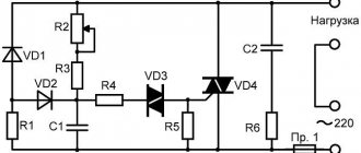
There is another scheme. It works a little differently: by providing a reverse type of energy flow, which is optimally beneficial. The circuit includes a fairly powerful thyristor.
Scheme 6 - Design of a thyristor regulator.
The circuit consists of a control signal generator, an amplifier, a thyristor and a circuit section that functions as a rotor rotation stabilizer.
The most universal circuit is a regulator based on a triac and dinistor (scheme 7). It is able to smoothly reduce the shaft rotation speed, reverse the motor (change the direction of rotation) and reduce the starting current.
The principle of operation of the circuit:
- C1 is charged until U breakdown of dinistor D1 through R2.
- When D1 breaks, it opens the junction of triac D2, which is responsible for controlling the load.
The load voltage is directly proportional to the frequency component when D2 opens, which depends on R2. The circuit is used in vacuum cleaners. It contains universal electronic control, as well as the ability to easily connect 380 V power. All parts should be placed on a printed circuit board made using laser-iron technology (LUT). You can find out more about this board manufacturing technology on the Internet.
Thus, when choosing an electric motor speed controller, you can buy a factory one or make it yourself. Making a homemade regulator is quite simple, since if you understand the principle of operation of the device, you can easily assemble it. In addition, you should follow safety rules when installing parts and when working with electricity.
Smooth engine operation, without jerks or power surges, is the key to its durability. To control these indicators, an electric motor speed controller is used for 220V, 12V and 24V; all of these frequencies can be made with your own hands or you can buy a ready-made unit.
voltage regulation
Just recently (10 years ago), there were a limited number of frequency controllers for motor speeds on the market, and they were quite expensive. The reason is that there were no cheap high-voltage power transistors and modules.
But developments in the solid-state field have allowed electronics to bring power IGBT-like to the market. modules result in the massive appearance on the market of inverter air conditioners, welding inverters, and frequency converters.
At the moment, this frequency conversion is the main method of regulating power, productivity, speed of all devices and the drive of mechanisms in which an electric motor is used.
However, frequency converters are designed to control three-phase single-phase.
Motors can be controlled by electric motors:
- specialized three-phase inverters
- single-phase inverters with the exception of the capacitor
Converters for single-phase motors
Currently, only one manufacturer announces serial production of a specialized inverter for capacitor motors - INVERTEK DRIVES.
This is the model for E2
Optidrive uses special algorithms to ensure stable engine starting and operation.
In this case, it is possible to adjust the frequency upward, but in a limited frequency range, this is prevented by a capacitor installed in the phase-shifting circuit of the winding, as its resistance directly depends on the frequency of the current:
Xc=1/2?fC
f - current frequency
C - capacitor capacity
The output stage uses a bridge with four output IGBT transistors:
Optidrive E2 allows you to control the motor without excluding the circuit, then the capacitor without changing the design of the motor - in some models this is quite difficult to do.
specialized Advantages of frequency converter:
- intelligent control stable
- engine stable engine operation
- huge modern capabilities of the inverter:
- the ability to control the operation of the maintenance engine for certain characteristics (water pressure, air flow, speed under changing load)
- numerous protections (motor and device itself)
- sensor inputs for (digital and analogue)
- various outputs
- communication interface (for control, monitoring)
- preset PID
- speed controller
Disadvantages of using a single-phase inverter:
- frequency limited control
- high price
Use of three-phase emergency conditions for motors
A standard frequency converter has a three-phase voltage output. When connecting a single-phase motor to it, remove the capacitor from it and connect it according to the diagram below:
Geometric arrangement of the windings relative to each other in the stator of an asynchronous motor Phase 90°:
is a three-phase voltage shift of -120°, the consequence of this is that the magnetic field will not be pulsating, but circular and its level will be less than with a power supply with a shift of 90°.
In some capacitor motors, the additional winding is made thinner and the wire has a higher resistance.
operation Without a capacitor this will lead to:
- stronger heating of the winding (service life is possible, short circuits and interturn short circuits are reduced)
- different current in Many
The windings of the inverter have protection against current asymmetry in the windings, if it is impossible to disable this function, the operation of the device according to this circuit will be impossible
more:
- Advantages: low cost compared to specialized inverters
- the choice is huge in terms of power and manufacturers
- wider frequency regulation range
- all the advantages of the inverter (inputs/intelligent, outputs, operating algorithms, communication interfaces)
method Disadvantages:
- the need for preliminary selection of the inverter and motor for joint operation
- pulsating and reduced torque
- increased heating
- no guarantee when leaving three-phase, because Inverters are not designed to work with single-phase Source
We advise you to study - Linear LED lamps and their use
Types and selection criteria
To select a regulator, you need to be guided by certain characteristics for a particular case. Among all the criteria, you can choose the following:
- By type of control. For commutator-type motors, regulators with a vector or scalar control system are used.
- Power is the main parameter from which you need to build.
- By U band.
- By frequency range. You need to choose a model that meets the user's requirements for a particular case.
- Other characteristics, which include warranty, dimensions, equipment.
In addition, the regulator is selected more powerful than the electric motor itself according to the formula: Preg = 1.3 * Pmot (Preg, Pmot is the power of the regulator and the motor, respectively). It must be selected for different U ranges, since versatility plays an important role.
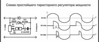
Thyristor device
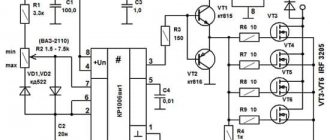
This model, shown in Diagram 1, uses 2 thyristors connected back-to-back, although they can be replaced with one triac.
Scheme 1 - Thyristor speed control of a commutator motor without loss of power.
This circuit performs regulation by opening or closing thyristors (triacs) during a phase transition through the neutral. To correctly control a commutator motor, the following methods of modifying circuit 1 are used:
- Installation of LRC protective circuits consisting of capacitors, resistors and chokes.
- Adding capacitance at the input.
- The use of thyristors or triacs, the current of which exceeds the rated value of the motor current in the range of 3..8 times.
This type of regulator has advantages and disadvantages. The first include low cost, low weight and dimensions. The second ones include the following:
- application for low power motors;
- there is noise and jerking of the motor;
- when using a circuit based on triacs, a constant U hits the motor.
This type of regulator is installed in fans, air conditioners, washing machines and electric drills. Performs its functions perfectly, despite its shortcomings.
Transistor type
Another name for a transistor-type regulator is an autotransformer or PWM regulator (scheme 2). It changes the value of U according to the principle of pulse width modulation (PWM) using an output stage that uses IGBT transistors.
Scheme 2 - Transistor PWM speed controller.
Switching of transistors occurs at a high frequency and thanks to this it is possible to change the width of the pulses. Consequently, the value of U will also change. The longer the pulse and the shorter the pause, the higher the value of U and vice versa. The positive aspects of using this variety are as follows:
- Low weight of the device with small dimensions.
- Quite low cost.
- At low speeds there is no noise.
- Control via low U values (0..12 V).
The main disadvantage of the application is that the distance to the electric motor should be no more than 4 meters.
Frequency regulation
Regulating the speed of motors of various types due to frequency is widely used. Frequency conversion occupies a leading position in the market for sales of speed control devices and soft starting. Thanks to its versatility, it is possible to influence the power, performance and speed of any device with an electric motor. These devices are used for single-phase and three-phase motors. The following types of frequency converters are used:
- Specialized single-phase.
- Three-phase without capacitor.
To regulate the speed, a capacitor is used, connected to the windings of a single-phase motor (diagram 3). This frequency converter (FC) has a capacitive R, which depends on the frequency of the flowing alternating current. The output stage of such an inverter is made of IGBT transistors.
Scheme 3 - Frequency speed controller.
A specialized inverter has its advantages and disadvantages. The advantages are the following:
- Blood pressure control without human intervention.
- Stability.
- Additional features.
It is possible to control the operation of the electric motor under certain conditions, as well as protection against overloads and short-circuit currents. In addition, it is possible to expand the functionality by connecting digital sensors, monitoring operating parameters and using a PID controller. The disadvantages include limitations in frequency control and a fairly high cost.
For three-phase IM, frequency control devices are also used (Scheme 4). The regulator has three phases at the output for connecting an electric motor.
Scheme 4 - inverter for a three-phase motor.
This option also has its strengths and weaknesses. The first include the following: low cost, choice of power, wide range of frequency regulation, as well as all the advantages of single-phase frequency converters. Among all the negative aspects, the main ones can be identified: preliminary selection and heating during startup.
Popular models of speed controllers for single-phase motors
Among the variety of devices that perform the function of controlling an electric motor, there are two main types of speed controller models. These are electronic thyristor single-phase speed controllers that operate by smoothly changing the supply voltage. The second type of speed controller models is a transformer single-phase speed controller. Its work is to change the position of a three-stage cam switch, which changes the switching combination of the windings.
Frequency control for speed control of asynchronous electric motors is a technical standard nowadays. The use of a frequency regulator has replaced many control methods. Symmetrical and asymmetrical voltage control and the use of additional resistances, changing the number of pole pairs are a thing of the past.
Frequency generator, frequency converter 220 - 380 motor speed controller
Watch this video on YouTube
Changing the speed of an IM with a squirrel-cage rotor
There are several ways:
- Rotation control by changing the electromagnetic field of the stator: frequency regulation and changing the number of pole pairs.
- Changing the slip of the electric motor by decreasing or increasing the voltage (can be used for IMs with a wound rotor).
Frequency regulation
In this case, the adjustment is made using a frequency conversion device connected to the engine. For this purpose, powerful thyristor converters are used. The process of frequency regulation can be considered using the example of the EMF formula of a transformer:
U1=4.44w1k1fΦ
This expression means that in order to maintain a constant magnetic flux, which means maintaining the overload capacity of the electric motor, the supply voltage level should be adjusted simultaneously with frequency conversion. If the expression calculated by the formula is saved:
U1/f1=U'1/f'1
then this means that the critical moment has not been changed. And the mechanical characteristics correspond to the figure below; if you do not understand what these characteristics mean, then in this case the adjustment occurs without loss of power and torque.
The advantages of this method are:
- smooth regulation;
- changing the rotor speed up and down;
- rigid mechanical characteristics;
- efficiency.
There is only one drawback - the need for a frequency converter, i.e. increase in the cost of the mechanism. By the way, on the modern market there are models with single-phase and three-phase input, the cost of which with a power of 2-3 kW is in the range of 100-150 dollars, which is not too expensive for full adjustment of the drive of machine tools in a private workshop.
Switching the number of pole pairs
This method is used for multi-speed motors with complex windings that allow you to change the number of pairs of its poles. The most widely used are two-speed, three-speed and four-speed IMs. The adjustment principle is easiest to consider on the basis of a two-speed IM. In such a machine, the winding of each phase consists of two half-windings. The rotation speed changes when connecting them in series or parallel.
In a four-speed electric motor, the winding is made in the form of two parts independent from each other. When the number of pole pairs of the first winding changes, the speed of the electric motor changes from 3000 to 1500 rpm. Using the second winding, rotation is adjusted at 1000 and 500 rpm.
When the number of pole pairs changes, the critical moment also changes. To keep it unchanged, it is necessary to simultaneously regulate the supply voltage while changing the number of pole pairs, for example, by switching the star-delta circuit and their variations.
Advantages of this method:
- rigid mechanical characteristics of the engine;
- high efficiency.
Flaws:
- step adjustment;
- large weight and overall dimensions;
- high cost of the electric motor.
Frequency converter: types, principle of operation, connection diagrams
The frequency converter allows its owner to reduce energy consumption and automate processes in equipment and production management.
The main components of the frequency converter: rectifier, capacitor, IGBT transistors assembled into an output stage.
Thanks to the ability to control the parameters of the output frequency and voltage, a good energy-saving effect is achieved. Energy saving is expressed in the following:
- The engine maintains a constant current torque of the shaft. This is due to the interaction of the output frequency of the inverter converter with the engine speed and, accordingly, the dependence of voltage and torque on the engine shaft. This means that the converter makes it possible to automatically regulate the output voltage when it detects a voltage value that exceeds the norm with a certain operating frequency necessary to maintain the required torque. All inverter converters with vector control have the function of maintaining constant torque on the shaft.
- The frequency converter is used to regulate the operation of pumping units (see page). When receiving a signal from a pressure sensor, the frequency generator reduces the performance of the pumping unit. As the engine speed decreases, the output voltage consumption decreases. Thus, standard water consumption by a pump requires 50Hz industrial frequency and 400V voltage. Using the power formula, you can calculate the ratio of power consumption.
By reducing the frequency to 40Hz, the voltage is reduced to 250V, which means that the number of pump revolutions is reduced and energy consumption is reduced by 2.56 times.
Rice. No. 6. Using a Speedrive frequency converter to regulate pumping units using the CKEA MULTI 35 system.
To increase the energy efficiency of using a frequency converter in electric motor control, you must do the following:
- The frequency converter must match the parameters of the electric motor.
- The frequency generator is selected in accordance with the type of working equipment for which it is intended. Thus, the frequency converter for pumps operates in accordance with the parameters included in the program to control the operation of the pump.
- Precise settings of control parameters in manual and automatic mode.
- The frequency converter allows the use of energy saving mode.
- Vector control mode allows automatic adjustment of engine control.
Selecting a frequency converter
When designing a variable frequency drive, it is necessary to take into account many nuances. When choosing a frequency generator, they are guided by the following criteria:
- Purpose of the converter. Many manufacturers produce inverters designed for electric motors of pumps, elevators, electric drives of ventilation systems, as well as universal devices for general industrial use. Specialized frequency generators are produced for specific technological equipment. The possibility of their adaptation is significantly limited. General industrial frequency controllers can be configured for various drives.
- Control method and support for various communication protocols. Variable frequency drives are usually integrated into complex automation and remote monitoring and control systems. The frequency converter must be equipped with a controller that supports communication using the protocol used in a specific process control system.
- Power and reload capacity. The rated electrical power of the converter should be 15-30% greater than that of the electric motor. When calculating power, the starting currents of the electric machine, peak loads on the engine and their duration are taken into account. Errors lead to overheating of the frequency converter and failure of power transistors or thyristors.
- Range and accuracy of regulation. The frequency change interval and the accuracy of its setting must meet the requirements of the technological process conditions. The ability to change the frequency of scalar converters is 1:10; if a wider range is required, a frequency converter with vector control is required.
- Electromagnetic compatibility. The frequency converter is sensitive to electromagnetic interference and is itself a source of it. The device is selected based on its installation conditions. If necessary, it may be necessary to install it in a separate room, connect special filters and use shielded cables. produces converters equipped with built-in EM filters.
- Availability of functions for shutting down the engine in case of overheating, phase imbalance, overloads, and other emergency and abnormal operating modes.
- Availability of automated event management. To synchronize the operation of industrial equipment, frequency generators are needed that have control functions to achieve a certain value of technological parameters.
- Number of inputs and outputs for connecting remote control and monitoring devices. In case of modernization of the automatic control system or complication of the automatic transmission system, it is recommended to select frequency units with an excessive number of analog and discrete connectors. For electric drives of automated systems, it is recommended to select a frequency controller with built-in memory and an event logging function.
- Rated current and voltage. The electrical parameters of the frequency generator must correspond to the characteristics of the electric motor.
The choice of a frequency regulator for industrial equipment is made on the basis of calculations using specialized methods. The slightest mistakes can lead to accidents that can have unpredictable consequences. It is advisable to entrust the design of an electric drive and the choice of inverter to automation specialists. The correct choice of frequency generator provides energy savings of up to 40-50%, reduces the cost of repair and maintenance of the electric drive and provides a good economic effect.
Technical features of using a frequency drive
- To ensure high performance, you can freely switch to any mode in the settings.
- Almost all devices have diagnostic functions, which allows you to quickly resolve the problem. However, it is recommended to first check the settings to eliminate the possibility of involuntary actions by employees.
- An adjustable drive can synchronize conveyor processes, or set a certain ratio of interdependent quantities. Reducing equipment leads to optimization of technology.
- In the auto-tuning state, the motor parameters are automatically stored in the memory of the frequency converter. This increases the accuracy of torque calculations and improves slip compensation.
Application area
Manufacturers offer a wide range of drives used in areas where electric motors are used. Ideal solution for all types of loads, including pumps and fans. Mid-range systems are used in coal-fired power plants, mining, mills, utilities, etc. The rating range is as follows: 3 kV, 3.3 kV, 4.16 kV, 6 kV, 6.6 kV, 10 kV and 11 kV.
With the advent of an adjustable electric drive, controlling water pressure does not cause problems for the end user. The interface with a well-thought-out script structure is ideal for controlling pumping equipment. Thanks to its compact design, the drive can be installed in a variety of cabinet designs. New generation products have the properties of advanced technology:
- high speed and accuracy of control in vector mode;
- significant energy savings;
- fast dynamic characteristics;
- large low-frequency torque;
- double braking, etc.
Purpose and technical indicators
Complete VFDs with voltages up to and above 1 kV (designed for receiving and converting energy, protecting electrical equipment from short-circuit currents, overloads) allow:
- smoothly start the engine, and, therefore, reduce its wear;
- stop, maintain engine speed.
Complete cabinet-mounted VFDs up to 1 kV perform the same tasks in relation to motors with a power of 0.55 - 800 kW. The drive operates normally when the mains voltage is between -15% and +10%. During non-stop operation, power reduction occurs if the voltage is 85%-65%. Overall power factor cosj = 0.99. The output voltage is automatically regulated by an automatic transfer switch (ATS).
Benefits of use
From an optimization point of view, the potential benefits provide the opportunity to:
- regulate the process with high precision;
- remotely diagnose the drive;
- take into account engine hours;
- monitor malfunctions and aging mechanisms;
- increase the service life of machines;
- significantly reduce the acoustic noise of the electric motor.
Features of speed control
It is important to know that each motor, when rotating, consumes not only active, but also reactive power. In this case, the reactive power level will be higher, which is due to the nature of the load
In this case, the task of designing devices for regulating the rotation speed of commutator motors is to reduce the difference between active and reactive powers. Therefore, such converters will be quite complex, and it is not easy to make them yourself.
You can construct only some semblance of a regulator with your own hands, but there is no point in talking about saving power. What is power? In electrical terms, it is the current drawn multiplied by the voltage. The result will give a certain value that includes active and reactive components. To isolate only the active one, that is, to reduce losses to zero, it is necessary to change the nature of the load to active. Only semiconductor resistors have these characteristics.
Therefore, it is necessary to replace the inductance with a resistor, but this is impossible, because the motor will turn into something else and obviously will not set anything in motion. The goal of lossless regulation is to maintain torque, not power: it will still change. Only a converter can cope with such a task, which will control the speed by changing the duration of the opening pulse of thyristors or power transistors.
Difficulties in PWM speed control of a DC motor
PWM is a popular method for regulating analog voltage in various circuits. When using this control method, the user may experience unpredictable motor behavior. For example, the shaft may begin to rotate in the opposite direction. This occurs at low capacitive loads. In commutator motors, the armature windings are constantly switched during operation. When the regulator is connected, the power switches off and on at a certain frequency. Additional commutation in combination with a commutator can lead to problems with engine operation. Therefore, control devices with PWM motor control must be carefully thought out and designed.
Also, the cause of unstable operation of the electric motor may be the fact that the current strength influences the rotor rotation speed, which depends on the level of applied voltage. Problems may arise when operating motors at low speed relative to the rated speed.
For example, the user has a motor that, at rated voltage, rotates the rotor at a speed of 10 rpm. To reduce the speed to 1 rps, it is not enough to simply reduce the voltage to 1V. It is difficult to select the appropriate value of the supplied voltage, and even if the user succeeds, with a slight change in operating conditions, the speed will change again.
The solution to the problem is to use an automatic control system or briefly turn on the electric motor at full power. The rotor will move jerkily, but with the correct frequency and duration of the applied pulses, the rotation can be made more stable. Thus, they achieve stable movement of the electric motor shaft at any speed that will not change depending on the load.
Single-phase frequency converter
The compact frequency conversion device is used to control single-phase electric motors for household equipment. Most frequency converters have the following design capabilities:
- Most models use the latest vector control technologies in their design.
- They provide improved torque for single-phase motors.
- Energy saving is set to automatic mode.
- Some models of frequency converters use a removable control panel.
- Built-in PLC controller (it is indispensable for creating data collection and transmission devices, for creating telemetry systems, and integrates devices with various protocols and communication interfaces into a common network).
- Built-in PID controller (monitors and regulates temperature, pressure and technological processes).
- The output voltage is adjusted automatically.
Fig. No. 7. Modern Optidrive converter with basic functional features.
The frequency converter does not serve for double voltage conversion; due to the presence of a PWM regulator in the design, it can increase the voltage value by no more than 10%.
The main task of a single-phase frequency converter is to provide power to both single- and three-phase electric motors. In this case, the motor current will correspond to the connection parameters from a three-phase network and remain constant
We advise you to study - Design and soft start circuit of an asynchronous electric motor
Operating principle of a single-phase asynchronous machine
When an asynchronous machine is supplied with single-phase power, instead of a rotating magnetic field, a pulsating one appears in it, which can be decomposed into two magnetic fields, which will rotate in different directions with the same frequency and amplitude. When the electric motor rotor is stopped, these fields will create moments of the same magnitude, but of different signs. As a result, the resulting starting torque will be zero, which will not allow the engine to start. In its properties, a single-phase electric motor is similar to a three-phase one, which operates with a strong distortion of voltage symmetry:
Figure a) shows a diagram of an asynchronous single-phase machine, and b) a vector diagram
Frequency controller structure
Currently, two main topologies of multilevel frequency converters have been developed in detail and are widely used. These are cascade and converters based on multi-level frequency voltage inverters.
Rice. No. 3 Block diagram of a high-voltage multilevel frequency converter, built on the basis of air- or water-cooled IGBT transistors.
The device includes a multi-winding transformer. Features of the circuit include the presence of power cells with a serial connection, due to which a total high voltage is obtained at the output of the device. Such a circuit serves to obtain an output voltage shape that is almost close to an ideal sine wave. The presence of cells that are shunted at the time of malfunction determines the high reliability of the circuit.
As a continuation of the previous circuit, we will consider a converter circuit based on a transformer multilevel voltage inverter with pulse width modulation using IGBT modules. The device is characterized by a fixed PWM frequency of 3 kHz. The structure of the device includes a protection system using a microprocessor.
Rice. 4 Block diagram of the converter.
The diagram shows that all blocks are functionally interconnected. The diagram shows how a frequency regulator works for an asynchronous motor, its structure and principle of operation.
The first block contains an input transformer; the block transmits electricity from a three-phase high-voltage power source. From the multi-level transformer, the reduced voltage is distributed into the inverter cabinet to the multi-level inverter.
The inverter cabinet includes a multi-level three-phase inverter consisting of converter cells. Each contains a six-pulse filter for rectifying the DC link and a bridge voltage inverter based on IGBT transistors. According to the circuit, the input alternating current is rectified, which, thanks to the inverter, is changed into alternating current with adjustable frequency and voltage.
The control protection cabinet contains a microprocessor unit with multifunctional capabilities and a power supply system from the converter TSN, a converter input device and primary sensors indicating the operating modes of the converter.
The microprocessor is used to generate inverter control signals depending on the designated operating algorithm. It is used to process information collected from voltage and current sensors. The microprocessor generates signals to control protections and emergency control buttons, and adjusts the control algorithm.
Fiber optic cable is used to transmit information and communication. For uninterrupted operation there is an independent built-in power supply. Parameter editing is performed using the remote control.
For reliable shutdown and safe performance of various types of work, the converter is equipped with a linear disconnector.
Rice. No. 5 Generalized diagram of the converter cell
Controlled alternating voltage sources form a voltage phase to perform their series connection. The output circuit of the supply network of an asynchronous motor occurs according to the “Star” winding connection diagram. The voltage in a three-phase inverter is distributed according to the circuit.
Rice. No. 6 Voltage distribution diagram in the inverter into three phases.
Voltage regulation
Speed regulation in this way is associated with a change in the so-called sliding motor - the difference between the rotation speed of the magnetic field created by the stationary stator of the motor and its moving rotor:
S=(n1-n2)/n2
n1 - magnetic rotation speed
n2 — rotor rotation fields
In this case, sliding energy is necessarily released - which is why the windings of the motor heat up more.
This method has a small regulation range, approximately 2:1, and can only be carried out downwards - that is, by reducing the supply voltage.
In order to control the speed control voltage in this way, it is necessary to install motors with increased power.
But despite this, this method is used quite often in low-power engines with a fan load.
In practice, various Autotransformer circuits are used for this.
regulators voltage regulation
An autotransformer is an ordinary transformer, but with one winding and with taps from the Pri part. There is no galvanic isolation from this turns, but the network is not needed in this case, so savings are achieved due to the absence of a secondary winding.
The diagram shows the autotransformer T1, the switch SW1, which receives different voltages from the taps, and the motor M1.
Adjustment is usually obtained in a stepwise manner, no more than 5 steps of regulation are used.
Advantages of this scheme:
- undistorted pure output waveform (sinusoid voltage)
- good overload capacity Disadvantages
transformer:
- large mass and dimensions of the transformer (power depends on the load motor)
- all the disadvantages of regulation inherent in voltage
Thyristor speed controller for this
In the motor circuit, switches are used - two switched on, thyristors are counter-parallel (the voltage is alternating, each thyristor therefore transmits its half-wave or) voltage triac.
The control circuit regulates the opening and closing moment of the thyristors relative to the phase one through the zero transition; accordingly, a piece is “cut off” either at the beginning, less often at the end of the voltage wave.
Thus, the root mean square value of the voltage changes.
This circuit is quite widely used for active load control - incandescent lamps and all kinds of heating devices (so-called dimmers).
Another way of regulation is to skip half-cycles of the wave at a voltage frequency of 50 Hz for the engine, this will be noticeable - noise and jerking at For.
When controlling motors, regulators are modified due to the inductive characteristics of the load:
- install protective LRCs for the power switch protection circuit (capacitors, chokes, resistors)
- add a capacitor at the output to shape the voltage wave correction
- limit the minimum regulation of voltage power - for a guaranteed start they use
- motor thyristors with a current several times higher than the electric motor current
Advantages of thyristor regulators:
- low cost
- low weight and dimensions
Flaws:
- Can be used for low power engines
- during operation there may be noise, crackling, jerking when
- motor using triacs, the motor receives DC voltage
- all the disadvantages of voltage regulation
It is worth noting that in most modern air conditioners of the highest and mid-level, the fan speed is regulated in this way.