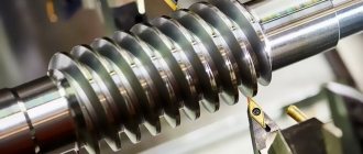
When to use center mounting
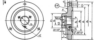
installation of the workpiece using a mandrel: 1 - middle part of the mandrel; 2 - flat; 3 — center holes; 4 - blank
- This is how long parts are machined, the length of which is five times the diameter;
- if you need to create concentricity of surfaces during fixation;
- the further stage of turning takes place on grinding equipment;
- technology does not provide for other methods.
Processing Features
Rigidity of installation in the centers will be ensured if the ratio of length and diameter is maintained to 12-15. Longer parts are supported by rests.
Center holes on the workpiece are made during the preparatory operation using a center drill.
Turning involves an automatic cycle. The machine can be easily reconfigured to produce parts with different dimensional parameters by making changes to the control program. The time required for an operation can be reduced by 1.5-2 times compared to working on a universal machine.
The work is based on the use of a contour processing system with linear-circular interpolation. The system performs processing of a complex contour, divided into roughing and finishing passes. The final operation is carried out by traversing the contour of the part by the working element in one pass.
The tool path when producing parts in a series of roughing passes is parallel to the axis of rotation of the part, perpendicular or at an angle. During the first pass, a layer of scale is removed from the workpiece and existing shape defects are corrected. The remaining roughing passes have a constant depth of cut.
After completing the working pass, the tool is retracted and the idle transition is carried out parallel to the contour, perpendicular to it or along an inclined path.
When manufacturing shafts on multi-stage profile machines, the allowance is divided into sections perpendicular to the axis of the part. The sequence of the turning operation in elementary sections is set so that the processing element travels the shortest distance.
Fastening technology
rear center as support for long parts
The workpiece is fixed in the centers using special mandrels. To do this, the mandrel cone should not exceed 1:2000. At the preparatory stage, central recesses are made at the ends of the part into which the tops of both centers will be inserted. The mandrel is treated with lubricant and the blank is pulled tightly. For greater density, gently tap the end of the mandrel with a wooden block. Securing the part in this type of mandrel may vary depending on its diameter.
The movement of the blank is transmitted through a driving chuck, which is put on the spindle thread. The pin of the drive chuck forces the blank to rotate. This method is more dangerous for the machine operator, so it is preferable to use a drive-type faceplate with a protective cover. The bolt is secured with a clamp, which rests on the flat of the mandrel.
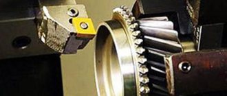
Content:The installation of workpieces with holes (for example, gears or bushings) occurs using centering mandrels of various shapes. One type of mandrel has a cylinder-shaped neck; a workpiece is placed on it and secured with a washer and nut. The nut is pressed against the collar and secures the resulting structure. A clamp is attached to the left with a screw. The part is fixed in the turning machine by recesses at the end sections of the mandrel.
Fastening workpieces.
- Three jaw chucks
- Four jaw chucks
- Collets
- Centers, driving chuck
Fastening workpieces.
Three jaw chucks
The most common way to hold workpieces on a lathe is to hold the workpieces in a self-centering three-jaw chuck. When the clamping key is rotated clockwise, all three jaws move to the center of the chuck at once. In this case, the workpiece is secured. When the key is rotated in the opposite direction, the workpiece is released. When using long rods as workpieces, it should be kept in mind that the diameter of the rod should not exceed the diameter of the machine spindle hole.
| When securing workpieces of large diameter, reverse jaws should be installed in the chuck. The workpiece, when fastened, must be tightly pressed with its rear end surface to the side surfaces of the cams. For ease of fastening, you can use the tailstock, “pressing” the workpiece, and then secure the workpiece with a clamping key. After this, the tailstock should be moved to the right. |
| When changing jaws in the chuck, you should unscrew the installed jaws and install the ones needed for the selected type of work. The jaws in a self-centering chuck move in a spiral. To ensure correct installation of the cams, you should pay attention to the number of the cam being installed. Jaws for the chucks are supplied as a set. |
| Each cam is marked with a number. Cam number 1 is inserted first, then cam number 2, and so on. |
| There are cartridges in which the cams do not unscrew when changing, but are unscrewed from the movable sole. Other cams are installed in place of the removed cams. When processing in self-centering chucks, it should be borne in mind that the part must be processed in one installation. If you partially process a part and then remove it from the machine, then reinstalling it on the machine will be problematic, since it is almost impossible to perfectly install the part (since it was previously attached). In this regard, during processing, the part will experience radial and end runouts, which may exceed the processing allowance. |
Four jaw chucks
| Four-jaw chucks are used in cases where the part has eccentric surfaces (the workpiece fastening axis does not coincide with the axis of the surface being machined) or when the base part of the part intended for mounting on the machine is not cylindrical in shape. The jaws of the four jaw chucks move independently of each other in the chuck, due to which a part of almost any shape can be secured in the chuck. |
| The production of a part in four jaw chucks should be done in one installation. Along with four jaw chucks, for fastening parts with complex shapes, there are chucks with a large number of jaws. |
Collets
| Fastening parts in collets is based on the fact that the workpiece is inserted into the end hole of the collet. The collet is pressed into the collet chuck and, due to the slots in the collet and its conical surface, the slots narrow and, accordingly, the diameter of the collet hole decreases, compressing the part. The collet is pressed into the chuck using the threaded collet cap. Most often, fastening workpieces in collets is used for finishing parts. |
| The advantage when fastening parts in collets is that there is practically no radial runout of the part. Collets are often used in numerically controlled machines, where it is easy to secure workpieces using automatic mechanisms. On a lathe, a collet chuck is secured in a tapered hole in the spindle. |
Centers. Drive chuck
| When processing parts with significant length and small diameter, center processing is used. In the simplest case, the workpiece is fixed in the chuck, and the end part of the workpiece is pressed by the center. With this type of fastening, the part should be processed in one installation. The center is attached to the tailstock quill using a tapered shank. | ||
| A centering hole must be pre-drilled at the end of the workpiece. The centering hole is made with a special tool - a centering drill (centering drill). The most common sizes of center drills: D1 (mm) | D2 (mm) | L (mm) |
| 1,0 | 3,15 | 31,5 |
| 1,6 | 4,0 | 35,5 |
| 2,0 | 5,0 | 40,0 |
| 2,5 | 6,3 | 45,0 |
| 3,15 | 8,0 | 50,0 |
| 4,0 | 10,0 | 56,0 |
| 5,0 | 12,5 | 63,0 |
| 6,3 | 16,0 | 71,0 |
| ©Gukov Konstantin Mikhailovich 2006 - 2012 Mail: |
Center designs
Turning centers can have different designs. The most common one is a cone, a workpiece is put on it, as well as a conical shank. The shank must match the holes of the quill and spindle of the machine.
To secure workpieces with external cones, reverse centers are used. The tapered end should coincide with the middle of the shank. To check the coincidence, the center is inserted into the spindle and started at low speeds. The serviceability of the part is indicated by the absence of runout.
The rear center is most often stationary, the front center rotates with the workpiece and spindle. As a result of friction, both surfaces fail, so it is necessary to apply lubricant:
- chalk - 25%;
- grease - 65%;
- graphite - 5%;
- sulfur - 5%.
Before mixing, it is necessary to grind the sulfur and chalk into powder without lumps. If lubricant is not used, the surfaces of the centers will collapse and their configuration will change.
When turning workpieces at high speeds, the centers wear out faster, and the hole in the end of the part itself increases. To reduce the destruction of the rear cone, a wear-resistant layer is fused onto it.
The standard center is used at speeds up to 120 rpm. When working with bulky and heavy workpieces at high speeds, when removing large chips, the structure has little rigidity: the part begins to vibrate and can be pressed out.
rotating center
Therefore, they use rotating centers mounted in the rear rack. It contains a spindle that rotates in an angular contact bearing. For high loads, a roller bearing is preferable; for medium loads, a ball bearing is preferable.
Securing the workpiece in the lathe
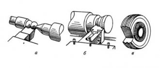
Before turning, the workpiece must be secured. There are several methods and devices for this: fastening in the centers of both headstocks and fastening the workpiece to the outer or inner surface, fastening in chucks, etc. (Fig. 29).
Rice. 29. Methods of securing wooden blanks: 1 - tailstock quill; 2 - front headstock
For this, various devices are used, shown in Fig. 30 and 31.
Rice. 30. Devices for securing and processing workpieces on a machine: a - trident; b - spiral self-centering cartridge; c — faceplate; g - cup cartridge; d — body with a fork center; e - cylindrical cartridge; g - a special cartridge with teeth; 1 - teeth; 2 - central tooth; 3 — fencing of teeth; 4 - cartridge cone
To secure the workpiece in the centers, a trident is used, which has the shape of a trident fork. When securing the workpiece, one end of it with the marked groove and center is inserted into the trident, and the other is pressed by the center of the tailstock quill.
The workpiece can be secured to the outer surface using cup, vice and jaw chucks or a faceplate.
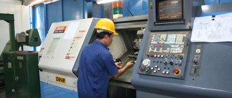
CNC automatic longitudinal turning machines
has a large fleet of automatic longitudinal turning lathes, which significantly expands the enterprise’s capabilities for producing parts of different types, and also allows you to quickly change the range of manufactured products by reducing the time for changeover. Modern automatic CNC longitudinal turning machines, thanks to their design, retain their main advantages, expressed in short processing time while maintaining important characteristics, such as high precision machining of parts, as well as excellent quality in terms of surface roughness of machined parts. Also, CNC turning allows us to produce both small and large batches of products.
Performed CNC turning work of this type (according to customer drawings):
- external turning;
- processing of grooves and cones;
- boring shallow holes;
- processing of shaped surfaces;
- internal and external thread cutting;
- opening holes;
- knurling of external surfaces;
- slot milling;
- drilling
| Specifications | Hanwha XD-07, XD-20, XD-26 | NEXTURN SA12B | Doosan Puma ST20G | Doosan Lynx 220 | |
| Main spindle | Maximum processed length, mm | 125/210/210 | 160 | 200 | 305 |
| Maximum processed diameter, mm | 7/20/26 | 12 | 20 | 320 | |
| Maximum rotation speed, rpm | 16000/10000/8000 | 10000 | 10000 | 5000 | |
| Maximum power, kW | 1,5/3,7/5,5 | 2,2 | 3,7 | 15 | |
| Counter spindle | Maximum processed diameter, mm | 7/20/26 | 12 | 20 | 305 |
| Maximum rotation speed, rpm | 16000/8000/8000 | 10000 | 8000 | 6000 | |
| Maximum power, kW | 1,5/2,2,/2,2 | 1,1 | 2,2 | 5,5 | |
| Number of tools, units | 14/26/25 | 18 | 25 | 12 | |
| Moving | Number of axles, units | 4/4/5 | 7 | 7 | 3 |
Automatic longitudinal turning machines
Among the services that are often ordered from is metal turning using automatic longitudinal turning machines. Automatic longitudinal turning machines are the most common name for a type of lathe designed for the production of products from workpieces in the form of a rod or wire made of special calibrated steel or other metals. Operations that automatic longitudinal turning machines can perform include turning and drilling operations, boring and threading, milling grooves, splines, and pads in products.
| Specifications | Tornos M7, R10, R16 | 1B10a |
| Maximum processed length, mm | 60/100/150 | 60 |
| Maximum processed diameter, mm | 7/10/16 | 60 |
| Maximum spindle speed, rpm | 10000/8000/5450 | 10000 |
| Number of tools, units | 5/5/5 | 18 |