Electrode release
Distance from the torch nozzle to the end of the welding wire. As output increases, gas protection of the welding zone deteriorates. With a small output, the welding technique becomes more complicated, especially corner and T-joints.
Reach and release depend on the diameter of the electrode wire:
| Wire diameter, mm | 0,5-0,8 | 1-1,4 | 1,6-2 | 2,5-3 |
| Electrode extension, mm | 7-10 | 8-15 | 15-25 | 18-30 |
| Electrode outlet, mm | 7-10 | 7-14 | 14-20 | 16-20 |
| Gas consumption, l/min | 5-8 | 8-16 | 15-20 | 20-30 |
The optimal set of mode parameters makes the process stable at three stages:
1 - when the arc is ignited and the welding operating mode is established; 2 - in a wide range of operating modes; 3 - during the completion of welding.
The welding process is considered stable if its electrical and thermal characteristics do not change over time or change according to a specific program. In this regard, mechanized welding in shielding gases is carried out with a stationary arc, pulse-arc method, with a synergetic control system.
General information, classification, technological capabilities
In MAR (manual arc welding), ignition of the arc, maintaining its length during welding, moving along the edges to be welded and feeding the electrode into the arc burning zone as it melts is carried out by the welder manually. The quality of welding a joint largely depends on the qualifications of the welder: the ability to quickly ignite an arc, maintain its required length, evenly move the arc along the edges being welded, perform the required oscillatory movements of the electrode during welding, and weld the seam in different spatial positions.
Based on the number of electrodes, manual arc welding is divided into one-, two- and multi-electrode (with a bunch of electrodes). By the type of current used: for welding with direct and alternating current. You can weld with a single-phase or three-phase arc.
The most widely used welding is with a metal consumable electrode using direct and alternating current.
Other manual arc welding methods are used either to increase labor productivity (for example, electrode beam welding), or to obtain certain types of seams in welded joints (for example, when flange welding), or when welding alloy steels, non-ferrous metals and their alloys (for example , tungsten electrode welding).
Stationary arc welding
Random fluctuations in the electrode wire feed speed and arc length can disrupt the stability of the process and lead to short circuits. arc breakage. To avoid this, it is necessary to change the melting rate of the electrode, i.e. Vary the welding current accordingly.
The current-voltage characteristic of the arc (volt-ampere characteristic of the arc) in protective gases with a consumable electrode has an increasing character.
At a certain point in the stable welding process, the electrode wire feed speed Vп1 is equal to the melting speed Vpl1. In this case, the current and voltage parameters were determined by the operating point A1 with arc length ld1. Let us assume that due to malfunctions in the wire feed mechanism, the feed speed has decreased. Then a relative melting rate ΔVmel = Vmel1 - Vп2 arises, which leads to the movement of the operating point to a new position - A2. It is characterized by a decrease in welding current (Δl), which leads to a decrease in the initial melting rate. The welding process returned to point A1 with arc length ld1. This process is called self-regulation along the arc length. It becomes more intense with a more rigid voltage-ampere characteristic of the power source.
When welding from a source with a rigid characteristic, the welder adjusts the current mode by adjusting the wire feed speed. However, this changes the length of the arc and the voltage on it. To maintain the required arc length, when setting the mode, you should adjust the current-voltage characteristic of the power supply, moving from one (I) to another (II).
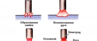
The stability of the arc, especially in the ceiling position, as well as the size of the weld and its quality depend on the type of transfer of electrode metal through the arc gap. There are three types of transfer.
1. Large droplet transfer with arc short circuits. Droplets are formed 1.5 times larger than the diameter of the electrode wire. The process is accompanied by short circuits with a natural pulse-arc process determined by the mode parameters. The voltage on the arc periodically decreases to 0 and at the moment of drop separation it increases to the operating value. The current at the moment of a short circuit increases, which leads to the detachment of a drop of electrode metal.
The process proceeds with metal spattering, which worsens the appearance of the welded joint, leading to lack of penetration and excessive convexity of the seam.
2. Medium drop transfer without short circuits.
The arc burns continuously, and the electrode metal is transferred through the arc in droplets whose diameter is close to the diameter of the wire.
Welding occurs with periodic changes in arc voltage and welding current.
The pulse-arc process depends on the parameters of the welding mode and is also accompanied by spattering, which reduces the quality of the weld.
3. Jet transfer.
The arc burns continuously, the melted end of the electrode is extended into a cone, from which drops measuring less than 2/3 of the electrode diameter flow into the weld pool. The mass of the drop is small, so the electrode metal is easily transferred to the pool during welding in all spatial positions.
Spattering during jet transfer is negligible. Productivity is high. Jet transfer can be obtained in argon. In carbon dioxide, this transfer is achieved at high welding current densities or with wires activated by rare earth elements
Controlled transfer of electrode metal with the required droplet sizes is successfully achieved using a pulsed-arc process, when the arc voltage and welding current are periodically changed.
Determination of modes and technological coefficients
Ministry of Education and Science of the Russian Federation Federal State Autonomous Educational Institution of Higher Education "NORTH CAUCASUS FEDERAL UNIVERSITY"
Guidelines
for performing laboratory work in the discipline
"Metal structures, including welding"
for bachelor students in the field of "Construction"
08.03.01 “Industrial and civil construction”
Stavropol, 2017
This publication presents methods for performing laboratory work in the discipline “Metal structures, including welding.”
Laboratory work in this discipline includes: determining the characteristics of welding arc power sources; determination of melting, deposition and loss coefficients; determination of deformations in a welded joint; defects and quality control of welded joints of metal structures. Each work contains: goals and content; theoretical justification; equipment and materials; safety instructions; methodology and procedure for performing work; contents of the report; questions for job protection.
The instructions correspond to the program of the discipline “Metal structures, including welding” for bachelor students in the direction of “Construction” 03/08/01 “Industrial and civil construction”
Compiled by: Gavrilova A.I., art. Rev.
Content
Management……………………………………………………………………………….4
1. Laboratory work 1 . Definition of characteristics
welding arc power sources
…………………………………………………….5
2. Laboratory work 2 . Definition of modes and
technological coefficients for manual electric arc
welding
………………………………………………………………………………………………….25
3. Laboratory work 3 . Determination of deformations
welded joints MK
……………………………………………………………………….39
4. Laboratory work 4. Defects and quality control
welded joints MK
…………………………………………………………………………….54
List of recommended literature……………………………………………………….64
Maintaining
Laboratory work in the discipline “Metal structures, including welding” allows students to become more familiar with:
− with the technology of performing welding work on direct and alternating current, the technology of applying butt and fillet welds;
− determine modes and technological coefficients for manual electric arc welding;
− determine the deformation of welded joints of metal structures;
− examine defects and be able to determine the quality of welded joints of metal structures.
Lab 1
Characterization of welding arc power sources
1 Purpose of the work
This work aims to familiarize students with the design of an AC and DC welding station for manual arc welding and determining the characteristics of the welding arc power sources.
for manual arc welding on alternating current
– familiarization with the equipment of the AC welding station;
– design and operation of the welding transformer;
– the principle of current regulation and reading its characteristics;
– welding of two plates end-to-end, overlapping, into a tee;
for manual DC electric arc welding
– familiarization with the equipment of a DC welding station;
– familiarization with the nature of arc burning in direct and reverse polarity;
– removal of static characteristics of a direct current arc with a carbon electrode;
Formed competencies or parts thereof
Knowledge of technology for designing parts and structures in accordance with technical specifications (PC-2), knowledge of testing methods for building structures and products, methods of setting up and conducting experiments according to given methods (PC-14)
2 Theoretical part
2.1 General basic theoretical principles
Welding is the process of permanently joining metal products by locally heating them to a molten or plastic state without or with the use of mechanical force.
When electric arc welding, the edges of the parts being welded, as well as electric
trode are melted by the heat of the electric arc burning between the parts being welded and the electrode. The electrode is a metal rod, which at the same time is a filler material.
Figure 1.1 – Electric arc welding: 1 – parts to be welded; 2 – electrode; 3 – electrode holder; 4 – flexible cable
Metal electrode 2 (Figure 1.1) is fixed in the electrode holder 3 and, using a flexible cable 4, is connected to one of the poles of the current source, and the parts to be welded 1 are connected to the second pole.
The resulting arc is a powerful concentrated heat source with a temperature of 4500 – 7000 °C. The arc melts the electrode and melts the base metal, forming a weld pool on it. The molten metal of the electrode drops into the weld pool, mixes with the molten base metal and forms a weld. The electric arc is powered by direct and alternating current. When welding on direct current, rectifiers and generators are used, when welding on alternating current, transformers are used.
The most common types of welded joints are: butt, lap, T, corner, flanged (Figure 1.2).
Figure 1.2 – Types of welded joints: a
– butt;
b
– overlap;
c
– tee;
g
– angular;
d
– flanged
Butt joint is a welded joint in which parts of products are connected along their end surfaces ( a
).
An lap joint is a welded joint in which the side surfaces of the joined products partially overlap each other ( b
).
T-joint is a connection in which the end of one of the products is connected to the side surface of another ( in
).
Corner connection - a connection in which the welded parts of the products are located at an angle (
).
Flanged connection - a connection in which the ends of the connected parts are flanged ( d
).
According to the degree of reinforcement, normal, weakened and reinforced seams are distinguished (Figure 1.3).
Figure 1.3 – Welds by degree of reinforcement: a
– normal;
b
– weakened;
c
– reinforced
A normal weld is a weld whose geometric (actual) height is equal to the design height ( a
).
A weakened seam is a seam whose geometric height is less than the height of a normal seam ( b
).
Reinforced seam - a seam that has a geometric height ( in
) is greater than the height of the normal seam. Depending on the spatial position, there are five positions of welds: bottom, horizontal, vertical, ceiling and boat.
The bottom seams are located in any direction on the lower horizontal plane.
Horizontal seams - located horizontally on a vertical plane.
Vertical seams - located on the upper horizontal plane in any direction. Manual arc welding modes are determined by the diameter of the electrode, the magnitude of the welding current, arc voltage, and the position of the seam in space.
The diameter of the electrode is selected depending on the thickness of the metal and the type of welded joint. The welding current is determined by the selected electrode diameter. The welding speed must also be taken into account. Welding current can be determined by the formula
I=K de
,
A,
(1.1)
where de
– electrode diameter, mm;
TO
– coefficient taking into account the coating of the electrodes and the properties of the metal being welded (
K
= 40 – 60, for low-carbon steel
K
= 50),
A
/
mm
.
With metal thickness <1.5 dе
The welding current should be reduced by 10 - 15%, with a metal thickness >3
dе
- it should be increased by 10 - 15%.
As the welding speed increases, the current should be increased. Welding of metals with low thermal conductivity, for example, chromium-molybdenum steels, is carried out with a current reduced by 10 - 20% compared to low-carbon steels. The greater the thickness of the metal being welded, the higher the current should be. The dependence of the welding current on the thickness of the parts being welded is presented in Figure 1.4.
Figure 1.4 – Dependence of welding current on the thickness of the parts being welded
To obtain high-quality welding, it is necessary to achieve complete fusion of the base metal with the electrode metal. This is achieved by good melting of the surface of the base metal and obtaining a crater of the proper depth. A crater is a depression formed by an arc in the molten base metal. High-quality welding is obtained with a penetration depth of the base metal of at least 1.5 - 2 mm. The amount of penetration is judged by the type of crater. To determine the depth of the crater, the arc is interrupted and the distance from the surface of the base metal to its bottom is measured. By adding 1 - 2 mm to this value, the penetration depths are determined. With the correct welding current, the weld bead will have edges that smoothly merge with the base metal (Figure 1.5 a
).
Figure 1.5 – Welding quality
The base metal under the roller is welded to a depth of 2–3 mm, so the roller is firmly fused with the base metal; resulting in a high-quality connection.
With a small current, the base metal is melted to a small depth and therefore the molten metal of the electrode is fused with the base metal only in the middle (Figure 1.5 b
). From the edges, drops of metal from the electrode fell onto the unmolten metal, and fusion did not occur in this place; as a result, the edges of the roller have a curved shape with a sharp transition to the base metal, and the seam turns out to be fragile.
With an excessively high current, the crater turns out to be very deep and is not completely filled with the electrode metal, due to which a depression is formed at the edges of the roller, which reduces the thickness of the base metal and, therefore, somewhat weakens the strength of the connection (Figure 1.5 c
).
2.2 Basic theoretical principles of manual electric welding with direct current
The main parameters characterizing welding arcs of various types (open, closed and protected, direct and alternating current, with consumable and non-consumable electrodes) include: voltage Ud,
current
Isv
and length
ld.
The relationship between the voltage on the electrodes and the current passing through the arc is called the static characteristics of the arc.
The static characteristic of the arc is a complex function, depending on the length of the arc, as well as on the material of the electrode and product, the diameter of the electrode, the composition and pressure of the gases filling the arc gap, etc.
The static characteristics of the arc for each given case are obtained experimentally.
The static characteristic of the arc is decreasing, that is, the arc ignition voltage is significantly greater than the operating voltage (Figure 1.6). From the curve in Figure 1.6 it can be seen that the voltage Ud
drops sharply in the initial section of the curve to a certain value with a slight change in current, and later, that is, with a stable welding arc, the current value does not affect the voltage.
The shape of the curve does not change if the arc length is changed. In this case, only the position of the curve in the coordinate system changes, since the voltage on the arc is proportional to the length of the arc. In practice, for a welding arc under normal conditions, ignition voltage U =
(40 – 60) V for direct current and (50 – 70) V for alternating current, and the operating voltage
Ud
linearly depends on
ld
and is expressed by the formula
Ud = a + bld
, where
Ud
is the arc voltage;
ld
– arc length;
a
and
b
are coefficients characterizing various arc burning conditions (electrode material, type of current, polarity),
a
characterizes the voltage drop across the electrodes;
for an open arc a
= (18 – 12) V with steel electrodes and
a
= 35–38 V with carbon electrodes;
b
characterizes the voltage drop per 1 mm of arc length;
for air conditions b =
(2.0–2.5) V,
ld
is determined for manual welding as (
0.5-0,
de,
where
de
is the diameter of the electrode in mm.
For steel electrode in manual welding Ud
= (16 – 28) V.
Figure 1.7 shows a graph of arc voltage versus arc length.
The arc ignition voltage must correspond to the open circuit voltage of the power source, that is, for conventional arc welding with steel electrodes, the external characteristic of the current source must be steeply falling.
Figure 1.8 shows characteristic curves of the external characteristics of various current sources. They cross the I
belonging to an arc with a metal electrode.
The intersection points will characterize Ud
- operating voltage and
Isv -
operating current.
The intersection of these curves with the horizontal axis (abscissa) will indicate the corresponding short circuit currents Ik
.
Thus, if the static characteristic of the arc is falling, then the external characteristic of the current source should be more steeply falling.
In this work, the student must become familiar with the nature of the combustion of a “carbon” arc in direct and reverse polarity (Figure 1.9).
With straight polarity, the positive pole is connected to the workpiece being welded, and the negative pole is connected to the electrode.
With reverse polarity, the positive pole is connected to the electrode, and the negative pole is connected to the workpiece being welded. With reverse polarity, the arc becomes unstable, and its appearance changes sharply, the arc column loses its definition, the arc takes on a curved appearance, very easily deviates to the side and goes out.
This difference in the appearance of the arc between the carbon electrode and the workpiece can be used to determine the polarity of the direct current.
Figure 1.6 – Arc characteristic Figure 1.7 – Dependence of
Ud
on
l
Figure 1.8 – Dependences of external characteristics of various current sources
Figure 1.9 – Character of combustion of a “carbon” arc of direct polarity ( a
) and reverse (
b
): 1 – cathode; 2 – arc halo; 3 – anode
3 Equipment and materials
3.1 For manual AC electric arc welding
AC welding station with all necessary equipment (12 stations). Electrodes for welding low carbon steel. Samples of low-carbon steel in the form of plates measuring 100×200×10 mm.
3.2 For manual DC electric arc welding
DC generator – 4 pcs., ammeter, voltmeter, electrode holder, tripod, carbon or graphite electrode, metal ruler, low-carbon steel plate measuring 150x250x20 mm.
4 Safety instructions
Only students who have undergone safety instructions are allowed to perform laboratory work. The laboratory work area should be isolated from the classroom teaching area. The presence of unauthorized persons in the work area is prohibited.
All contact connections must be cleaned and checked for tightness; measuring instruments must be corrected. The use of damaged devices is not permitted.
During breaks in work, as well as after finishing work, all devices must be turned off. It is prohibited to leave electrical appliances connected to the network unattended.
It is prohibited to turn on electric welding equipment without the permission of the training master or teacher.
Do not look into the electric arc with unprotected eyes.
When performing work, use a shield or mask, mittens, and an apron.
After completing welding work, remove the work area.
When carrying out work, there must be mixed lighting, that is, natural and artificial, which ensures illumination of the work area in accordance with the requirements of the standards.
5 Tasks
(
instructions for the order of work
)
5.1 Manual arc welding with alternating current
5.1.1 Description of installation of AC welding station
The electrical circuit of the AC welding station is shown in Figure 1.10.
Figure 1.10 – Electrical diagram of an alternating current welding station: 1 – choke; 2 – screw device; 3 – secondary winding of the transformer; 4 – primary winding of the transformer; 5 – electrode; 6 – product to be welded
The welding machine consists of a transformer and a current regulator (choke - regulator). The welding transformer converts the high mains voltage into a low voltage, but it is sufficient to ignite the arc (60 - 65) V.
The choke limits the short circuit current and regulates the welding current. The primary winding of the transformer 4 is connected to the network, and the inductor 1, consisting of a split core and a coil, is connected to the low voltage secondary winding 3.
The current is regulated by changing the inductive reactance. The moving part of the core is moved using a screw device 2, which ensures a change in the air gap and, consequently, the inductance of the inductor winding.
When the throttle handle is rotated clockwise, the air gap in the reactive coil core increases, the resistance increases and the self-induction current, which is in the opposite direction to the main current, decreases. Rotating the knob counterclockwise reduces the welding current as the gap decreases.
5.1.2 Description - electrodes, ignition of an electric arc, surfacing of bead welds, welding of two plates
The electrodes are metal rods with a diameter of 1 to 12 mm and a length of 250 – 450 mm. In practice, electrodes with a diameter of 2–6 mm are used for welding parts of various thicknesses. Electrodes with a diameter of 2 mm are used to weld parts up to 2 mm thick, with a diameter of 4 – 5 mm – parts with a thickness of 5 – 10 mm, with a diameter of 5 – 8 mm – parts with a thickness of over 10 mm.
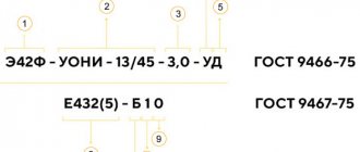
The surface of the electrodes is covered with coating to protect the molten metal bath from contact with oxygen and nitrogen in the air, to increase the stability of the arc and for other purposes. The most popular brands of electrodes for welding low-carbon steels are UONI - 13/45, ANO - 4, SM - 11, OMM - 5, TsM - 7 and others.
Composition of OMM coating – 5: titanium concentrate – 37%, manganese ore – 21%, feldspar – 13%, ferromanganese – 20%, starch – 9%, liquid glass – 30%,
Composition of coating CM – 7: hematite – 33%, granite – 32%, ferromanganese – 30%, starch – 5%, liquid glass – 30%.
Composition of coating UONI - 13: marble - 53%, fluorspar - 19%, quartz sand - 9%, ferromanganese - 2%, ferrosilicon - 3%, ferrotitanium - 15%, liquid glass - 30%.
The thickness of the coating layer ranges from (0.25–1) d
and more, where
d
is the wire diameter in mm.
The arc is ignited in two ways: the electrode touches the workpiece, quickly moves it vertically upward, or the electrode is passed along the surface of the metal and quickly moves it a short distance, exciting the arc. When the electrode is slowly removed from the product, the end of the electrode and the section of metal underneath it become very hot and, with slight pressure on the electrode, they are welded to one another. This phenomenon is called “freezing”.
When the electrode is withdrawn very quickly, the current discharge does not have time to heat the contact point and ionize the arc gap and, as a result, the arc does not ignite.
When the electrode freezes, it is necessary to rock it from side to side, this will allow it to be torn off from the product. Under normal welding conditions, the welder strikes the arc only when changing electrodes, that is, the entire electrode must be melted without interrupting the arc.
With a long arc, the melting of the electrode is accompanied by strong spattering and many large splashes of molten metal appear near the seam. The weld is uneven, with a large number of oxide inclusions, as a result of which the quality of the deposited weld metal deteriorates. When burning, a long arc produces a sharp and loud sound, often interrupted and accompanied by popping sounds.
With a short arc, a small number of small drops of metal will form near the seam, the electrode melts quietly, emitting a uniform sound of one tone, and the depth of penetration of the metal being welded is greater.
A short arc provides higher quality weld metal, largely free of oxygen and nitrogen from the air.
By moving the electrode along the welding line without transverse oscillatory movements, a bead of deposited metal of small width is obtained (a “narrow” bead).
The width of such a roller at normal arc speed is equal to approximately one and a half diameter of the electrode, and the length is the length of the molten electrode.
When moving the electrode along the welding line with transverse vibrations of the end of the electrode, a wide or widened bead is obtained.
Surfacing of bead (butt) welds should be done without rotating the plate. To increase the density of the deposited layer, surfacing beads are used in such a way that each subsequent one overlaps the previous one by 1/3 of its width. Before surfacing the next bead, the previous bead should be cleaned with a wire brush. Only with the permission of the master can a student proceed to welding two plates end-to-end or in a tee. When welding two plates end-to-end, the surfaces to be joined must be prepared: cleaned of rust, oil, paint and other contaminants using wire brushes, make an accurate adjustment of the surfaces to be welded, and in order to avoid warping of the plates, the extreme sections of the surfaces to be joined along the seam line are secured by welding. The technique for applying sutures in T-joints is as follows: the arc is excited on a horizontal surface at point A (Figure 1.12 a ) at a distance of 3 – 4 mm from the weld crater. Figure 1.12 – Technique for suturing T-joints The end of the electrode is then moved to the apex of the joint corner, where the arc is delayed to melt the apex of the corner; then the end of the electrode is moved to a vertical surface by an amount equal to the leg of the seam. When moving the electrode to a vertical surface, it is given a slightly inclined position 2 (Figure 1.12 b ) compared to position 1. Then the end of the electrode is moved down to the top of the corner and onto the horizontal surface at a distance equal to the leg of the seam. In this case, the electrode is given position 3 (Figure 1.12 b ). Next, the end of the electrode is moved along the horizontal surface in the direction of welding and to the crater, again directed to the top of the corner and all movements are repeated again. Welding speed is determined by measuring the length of the weld and the time it takes to deposit it. Before starting laboratory work with manual arc electric welding on alternating current, students become familiar with the design of a welding station on alternating current. 5.1.3 Work order 1. Take the external technical characteristics of the welding machine and write them down in Table 1.1. 2. For the electrodes used, indicate the brand and composition of the coating. Determine current strength I according to formula (1.1) and depending on the thickness of the parts being welded according to Figure 1.4. 3. Under the supervision of a master, learn to light an electric arc. 4. Under the supervision of the master, surfacing bead (butt) welds on the plate in different directions. 5. With the permission of the master, weld two plates end-to-end, overlapping, into a T-joint. 5.2 Manual DC electric arc welding 5.2.1 Installation description The work is performed on the installation of a DC welding station (Figure 1.13). Figure 1.13 – Installation of a DC welding station: 1 – welding current converter (generator); 2 – product; 3 – electrical holder; 4 – electrode; 5 – shunt; 6 – ammeter; 7 – voltmeter Before performing laboratory work on manual DC electric arc welding, students become familiar with the design of a DC welding station, check the switching circuit, and become familiar with the nature of arc burning in direct and reverse polarity. 5.2.2 Work order 1. Install the carbon electrode at a distance of 2 - 3 mm from the workpiece and take the static characteristic of the arc at a welding current of 80 to 200 A. 2. Install the carbon electrode at a distance of 5 - 6 mm from the workpiece and take the static characteristic of the arc at a welding current of 80 to 200 A. 3. Install the carbon electrode at a distance of 7 - 8 mm from the workpiece and take the static characteristic of the arc at a welding current of 80 to 200 A. 4. For each measurement, take the average reading of the oscillating needle of the device. The readings of the voltmeter and ammeter, as well as the calculated values, are placed in Table 1.3. 5. Based on the table data, graphs U=f(I) for different arc lengths. The scale of schedule implementation is recommended 1:1.5 or 1:2. 6. According to the data in Table 1.3, a graph of the dependence Ud= f(ld) and the values of the constants “ 6 Contents of the report 6.1 For manual AC electric arc welding The report must present: 1. Electrical diagram (Figure 1.10) and description of the welding station. 2. Technical characteristics of the welding machine in the form of table 1.1. Table 1.1 – Technical characteristics of the welding machine
3. Description of the electrodes used (brand, coating composition); 4. The results of welding two plates in the form of table 1.2; Table 1.2 – Results of welding two plates
5. Description of the work performed a) ignition of an electric arc; b) surfacing of bead (butt) welds in different directions; c) welding of two plates end-to-end, overlapping and in tees. 6.2 For manual DC electric arc welding The report must present: 1. Diagram of a DC welding station. 2. View of the welding arc in direct and reverse polarity. 3. Table 1.3. 4. Graphs U=f(I) . 5. Graphs of dependence Ud= f(ld) and calculation of the values of the constants “ Table 1.3 – Instrument readings and calculated values for manual DC electric arc welding
7 Test questions and test tasks 1. What is welding? 2. Tell us about how electric arc welding is performed? 3. Name and sketch the types of welded joints. 4. Describe the types of welded joints. 5. Based on the degree of reinforcement, what are the different types of fillet welds? Draw them and describe them. 6. Depending on the location in space, what are the different seams? 7. What determines the diameter of the electrode? How can you determine welding current? 8. How does the amount of current affect the quality of welding? 9. What is an electrode? 10. How is arc ignited? 11. Tell us about the sequence of roller (butt) welds. 12. At what width of the roller and at what angle of inclination of the electrode from the vertical are high-quality seams obtained? 13. Tell us about the technique of suturing in T-joints. 14. List the equipment of the AC welding station. 15. List the equipment of a DC welding station. 16. What is called the static characteristic of the arc? 17. What does the static characteristic of the arc depend on? 18. How is the static characteristic of the arc obtained in each given case? 19. Tell us about the procedure for performing manual arc welding on alternating current. 20. Tell us about the procedure for performing manual arc electric welding on direct current. List of literature recommended for use on this topic: main 1, additional 3,4,5,6. Lab 2 Determination of modes and technological coefficients |
Pulse arc welding
Pulse-arc (non-stationary arc) welding using the MIG/MAG method is possible with low welding current in all spatial positions of the seam with minimal spatter and high-quality seam formation.
There are two main types of electrode metal transfer:
- with continuous arc burning - “long arc”;
- with short circuits of the arc gap - “short arc”
The peculiarity of pulsed-arc welding with a consumable electrode is that the process of transfer of electrode metal can be controlled. When welding with a “long arc”, two types of transfer are possible:
- one pulse - one drop;
- one pulse - a few drops.
Short arc transfer is typical for carbon dioxide welding. Instability and increased spattering of the electrode metal are determined by the properties of the power source and depend on the nature of the change in instantaneous power both during the arcing period and during a short circuit.
In pulsed arc welding using the MIG/MAG method, synergistic process control is effective.
How to calculate welding speed
Welding speed is directly dependent on the size of the current, so you should first understand it. Welding current is calculated using formulas.
There are formulas by which the welding speed is calculated depending on the current value. This, in turn, can be calculated using the welding current formula. By correctly applying the formula for calculating the welding current, you can find its value and select the optimal welding speed, which depends on various characteristics.
So, for example, knowing the parameters of the deposited metal and the current value, you can apply the following formula:
αн is the deposition coefficient; γ —density of the electrode metal in g/cm3; Fн - metal area in cm2.
The deposition coefficient αн depends on the characteristics of the electrode. The metal area refers to the cross-sectional area of the welded seam under the condition of a single-pass option or one layer if a multi-layer coating is carried out.
To calculate this characteristic it is not necessary to use the welding speed formula. Regulatory documents can help, which contain recommendations on the choice for each type of metal. When asking how to calculate the welding speed, you can focus not only on the formulas, but also on the values indicated in them.
Synergetic management
Inverter power supplies allow you to accelerate changes in current parameters up to 1000 A/ms. The high speed of the source contributes to the optimal choice of pulse and pause currents, pulse and pause time, pulse frequency depending on the wire feed speed. This ensures stable transfer of a drop of electrode metal in one pulse.
In modern semi-automatic machines, microprocessor technologies have been introduced to control pulsed welding processes, depending on the steel grade, wire diameter, and type of shielding gas. Such systems are called synergetic.
Thanks to the pre-programming of pulse modes, only two parameters are regulated during welding: welding current and arc length . Synergetic equipment easily adjusts welding modes depending on the grade of steel being welded, the diameter of the electrode wire and the type of shielding gas.
In the synergetic equipment system, optimal welding mode parameters are programmed for various material combinations: carbon steel, stainless steel, aluminum alloys; diameters of solid electrode wire: 1.0; 1.2; 1.6 mm; crater filling time.
For each wire diameter there is a wide range of current mode values, which allows you to weld materials of different thicknesses and in all spatial positions. Synergic systems increase productivity by 20% compared to conventional MIG/MAG welding.
Welding mode parameters
Selecting a welding mode begins with parameters. There are basic and additional ones. Despite the names, they are all important and you need to be able to configure each parameter separately.
Main parameters:
- Welding current value.
- Type of current (direct, alternating) and polarity of current (reverse, forward).
- Arc voltage value.
- Diameter of the electrode used.
- Welding speed.
- The number of passes during which the seam is fused.
Extra options:
- Method of cutting edges, their shape.
- The quality of metal preparation for welding.
- Type of electrode used, brand, coating, etc.
- Welding position (horizontal, vertical, ceiling, etc.)
- Welding angle