Gas reducer: description, types, purpose.
Not all settlements and dacha cooperatives are connected to a centralized gas supply. Unfortunately, there are still towns and villages where gas cylinders are often used. For safety of use, they began to use a reducer for a gas cylinder - this is a special device that helps reduce the fuel pressure to the value required for boilers and stoves. We suggest considering all the information on choosing a reduction-type device. The information presented below will help you purchase the optimal reducer for your conditions for installation on a gas cylinder. All types of devices and the criteria by which to select the best models are described in detail here. For those who want to install it themselves, we offer step-by-step instructions. Here you will find all the rules, subject to which you can protect yourself and extend the life of gas installations.
Design and principle of operation
An autonomous regulator coordinates pressure without involving an additional energy source.
Devices are divided according to purpose, method of operation of the valve, nature of action, and method of adjustment. Standard structural elements:
- metal or PVC body;
- connecting pipe with nut;
- working connection;
- filtering unit;
- dual chamber with central membrane;
- seat valve on the axis;
- pressure gauge
The valves are single and double-seated, diaphragm; the design uses hose valves, taps and butterfly valves. The first two types of membranes are installed in city highways. They are sealed with rigid gaskets made of metal, rubber, fluoroplastic.
Setup and repair
It is possible to set up and repair a gas reducer yourself using available tools and a repair kit, but only if you know exactly what you are doing. Insufficiently qualified adjustment and assembly can lead to detrimental consequences. The main signs of abnormal operation of the product are as follows:
- deviation of outlet pressure from permissible limits;
- gas leak.
Pressure deviation is usually caused by a breakage or displacement of the spring, or the release of the compensating gas that performs its function due to depressurization of a part of the housing. But if the spring malfunction still needs to be eliminated using a repair kit, then the gas version falls into the non-repairable category (the entire device is changed).
Gas leakage can be caused by damage to the membrane, depressurization of the housing, or failure of the float valve. If the latter begins to leak gas, this may also manifest itself in the consuming product (for example, a gas water heater). Since the pressure at the output of the reducer is approximately equal to the input, then in the absence of flow (the consuming device is temporarily turned off), leakage will be inevitable.
Such a malfunction is difficult to diagnose because turning on the consuming device normalizes the situation. It can only be determined by measuring the gas pressure at the outlet of the reducer in the absence of consumption (as a rule, it should not exceed the nominal value by more than 20%).
But it is worth noting that gearboxes come in collapsible and non-dismountable (sealed) designs. The latter can only be replaced entirely.
So, having stocked up with the appropriate repair kit, the product must first be disassembled. By visually inspecting the spring and membrane removed from the housing, you should determine which of them caused the malfunction. A broken spring must be replaced with a new one from the repair kit.
If the spring is not broken, but simply compressed, having lost its elasticity over time, you can not change it, but simply select and place a gasket of the required thickness on the side of the body, without covering the existing hole.
If the membrane ruptures, it should be replaced using a similar one from the repair kit, but, as a rule, a tight connection with the washers enclosing it is not easy to make. Therefore, if you are unsure of your skill, think about the advisability of purchasing a new gearbox.
This is a tube with a small hole, at the end of which a rocker arm is pressed through a rubber gasket. There are several common problems with valve operation:
- the normal movement of the rocker arm is disrupted;
- the rubber gasket is worn or damaged;
- the end of the tube is deformed.
Adjusting the valve is a simple process. The mobility of the rocker can be restored by turning or replacing its hinges. The damaged gasket should be cut off and replaced with a similar one in size from the repair kit. The roughness and evenness of the end of the tube, ensuring a tight fit of the gasket, is achieved by grinding it.
If the gearbox malfunction consists of a gas leak due to leaks in the places where the membrane adheres to the housing, then the damaged integrity can be restored using silicone sealant. When making adjustments or repairs or for any other reason not initially related to depressurization, it would be a good idea to also apply sealant in these places, which will prevent a similar problem in the future.
Upon completion of repair work, you must immediately check the tightness of the product using a soap solution. If there are no bubbles that indicate leakage, the gearbox should be re-tested after one day, then after a few more days. Subsequently, periodic monitoring (eg monthly) is recommended.
Like any other gas-related equipment, the reducer will serve you well if you select the right model and take simple steps to ensure safe operation. Periodic maintenance and timely detection of faults will save you from trouble.
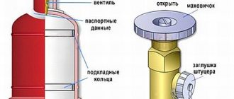
Installation procedure and volume
First you need to install gas supply hoses without direct connection to the cylinder. After this, install the nut from the gearbox on the valve and connect the hoses. With this method, the taps of appliances that operate on gas, gas water heaters, and stoves must be closed. Before connecting the gearbox, to loosen the spring, turn the adjustment screw all the way.
A type of adjustment screw in the form of a valve is more convenient than those designs that need to be tightened with screwdrivers. But children’s access to such a device should be limited. If you use ordinary flexible hoses, then for ease of work the fitting can be moistened with water. This connection is secured with a screw clamp. The bellows hoses are connected to a threaded adapter, which will be screwed in instead of the fitting.
After installing the system, a gas leak test should be performed with the space unoccupied. To do this, you need to tighten the valve for gas consumption, if available, and turn out the adjustment screw so that the spring is weakened to the maximum. After the system is assembled, you should ensure the flow of gas from the cylinder to the reducer and rotate the adjustment screw, and at the same time set the required outlet pressure. Afterwards, coat your hand with soapy water and move it from the cylinder to the consumption device to check for gas leaks.
If you use a gas stove as a consumption device, then you should light the burners sequentially, and if the flame on any of them is not blue, then you should reduce the pressure on the reducer. Yellow and orange flames mean that the fuel is not being burned completely, which means that prolonged use of the stove can become dangerous. When checking the operation of the burners at minimum heat, a fading problem may appear. To solve this, you should either slightly increase the outlet pressure using the adjustment screw on the cylinder reducer, or change the position of the flow screw on the plate.
If the problems described above are not typical for all burners, then the jets on the problematic stove unit should be cleaned or replaced. If a gas leak occurs during system startup, the shut-off valve should be fully closed. After ventilate the room, you can begin troubleshooting.
Disadvantages of gas heating on cylinders
Like any other heating method, this one also has its drawbacks:
- if the cylinder is located outside, in the event of severe frost the system may turn off - the condensate will freeze and will prevent the gas from escaping;
- Cylinders should not be placed in unventilated areas;
- Since the gas is heavier than air, if there is a leak, it can go down (to the basement, underground), and if the concentration is strong, serious consequences will arise.
Thus, heating using gas cylinders can be very dangerous if certain conditions are not met. Therefore, they need to be stored only in ventilated areas without a basement. It is even advisable to place them in a separate extension on the site. The room must be warm so that the system does not shut down in cold weather. If the extension is cool, you will have to make an insulated metal or plastic box for the cylinders. To insulate the walls, they are lined with foam plastic 5 centimeters thick. Ventilation holes must be made in the lid of the box.
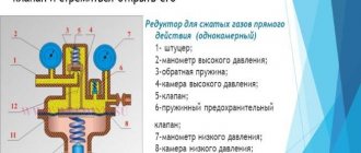
How does a cylinder reducer work:
1 Direct gearbox
An ordinary simple gas pressure reducing device consists of two chambers with an area of high and low pressure, separated by a rubber membrane. In addition, the “reducer” is equipped with an inlet and outlet fitting. Modern devices are designed in such a way that the bellows connection is screwed directly into the gearbox. Increasingly, you can find a gas reducer with a third fitting intended for mounting the monomer.
After gas is supplied through the hose and then through the fitting, it enters the chamber. The created gas pressure tends to open the valve. On the reverse side, a shut-off spring presses on the valve, returning it back to a special seat, popularly called a “saddle.” Returning to its place, the valve prevents the uncontrolled flow of high-pressure gas from the cylinder.
Membrane
The second acting force inside the gearbox is a rubber membrane that divides the device into high and low pressure areas. The membrane acts as an “assistant” to high pressure and, in turn, tends to lift the valve from the seat, opening the passage. Thus, the membrane is between two opposing forces. One surface is pressed by a pressure spring (not to be confused with the return spring of the valve), which wants to open the valve, on the other hand, the gas that has already passed into the low pressure zone presses on it.
The compression spring has manual adjustment of the pressure applied to the valve. We advise you to buy a gas reducer with a seat for a pressure gauge, this way it will be easier for you to adjust the spring pressure to the desired output pressure values.
As the gas leaves the reducer to the source of consumption, the pressure in the working space chamber decreases, allowing the pressure spring to straighten. She then begins to push the valve out of the seat, again allowing the device to be filled with gas. Accordingly, the pressure creeps up, pressing on the membrane and reducing the size of the pressure spring. The valve moves back into the seat, narrowing the gap, reducing the gas filling of the reducer. The process is then repeated until the pressure equalizes to the set value.
It should be recognized that gearboxes for direct type gas cylinders, due to their complex design, are not in high demand; reverse type gearboxes are much more widespread; by the way, they are considered devices with a high degree of safety.
2 Reverse gearbox
The operation of the device consists of the opposite action described above. Liquefied blue fuel is supplied to a chamber where high pressure is created. The bottled gas accumulates and prevents the valve from opening. To ensure gas flow into the household appliance, you need to turn the regulator in the direction of the right-hand thread.
On the back of the regulator handle there is a long screw, which, when screwed, presses on the pressure spring. As it contracts, it begins to bend the elastic membrane to the upper position. Thus, the transfer disk, through the rod, exerts pressure on the return spring. The valve begins to move and begins to open slightly, increasing the gap. Blue fuel rushes into the gap and fills the working chamber with low pressure.
In the working chamber, in the gas hose and in the cylinder, the pressure begins to increase. Under the influence of pressure, the membrane is straightened, assisted in this by a constantly compressed spring. As a result of mechanical interactions, the transfer disk lowers, weakening the return spring, which tends to return the valve to its seat. By closing the gap, the flow of gas from the cylinder into the working chamber is naturally limited. Then, with a decrease in pressure in the bellows liner, the reverse process starts.
In a word, as a result of checks and balances, the swing can be balanced and the gas reducer automatically maintains balanced pressure, without sudden jumps and drops.
Design features and maintenance
It is simply impossible for the system to operate without the slightest problem if regular maintenance is not carried out and even minor gearbox faults are not corrected. To do this, you should know what the design of the device is and what the signs of typical breakdowns are.
Diagram of reverse and direct action device
According to the type of design, gearboxes can be divided into devices with direct and reverse action. In the first case, excess pressure in the form of incoming gas will be directed to open the valve, and in the second, on the contrary, there is a lack of pressure in the working chamber of the structure. The design of a single-chamber reverse and direct-acting gearbox is quite simple. Due to the fact that there are no complex components, the device lasts for a very long time without breakdowns (provided that the product was made with high quality).
The main elements in both types of gearbox design are the same:
The fitting through which gas is supplied.- High pressure gauge, it shows the pressure of the gas that is supplied to the device.
- A return spring that works to close the valve.
- High pressure chamber.
- The valve and its position regulate the volume of gas that is passed through.
- A safety valve that is activated when an unacceptable pressure value appears inside the working chamber.
- Low pressure pressure gauge helps determine the operating pressure of the gas.
- Low pressure working chamber.
- An adjusting screw that determines the position of the membrane.
- Main spring.
- Membranes inside the working chamber.
- Pin between bypass valve and spring.
Reverse-action gearboxes have become much more common, as they are many times more reliable. There are models of the device with pneumatic pressure sensors, and instead of the main spring, there is a gas effect on the membrane, which ensures the balance of the system. Typically, the adjustment screw is tight, and this is directly related to the fact that it is impossible to allow a spontaneous change in position under the influence of a force directed at the membrane. When clockwise rotation occurs, the volume of the working chamber decreases and the pressure of the outlet gas increases.
In standard gearboxes, the unevenness of the output pressure will depend on the value of the input pressure, and reach approximately 15 to 20%. Two-chamber models are used if it is necessary to maintain the exact pressure of the exhaust gas.
This oxygen gas reducer perfectly demonstrates the two-stage design - it is essentially two separate devices that are connected together. Such devices have a more complex design and are slightly larger, and are also more expensive than their single-chamber counterparts. For this reason, it is not advisable to use them unless there is a need.
Periodic inspection and service work
For proper and long-term operation of the gearbox, certain procedures must be carried out regularly. So, once a week you should record readings from the pressure gauge, and as the elasticity of the springs decreases, a slow but constant increase/decrease in pressure will be noticeable.
Once every 3 months you should do the following:
- Check the tightness of the mating gaskets, pressure gauges, product body and safety valve. This procedure can be performed by applying a soap solution to areas where leakage is possible.
- Bleed the safety valve to prevent it from sticking. To do this, connect the reducer to a source of compressed air, and then, when the outlet is closed, increase the pressure until the protective mechanism is activated.
Also, repair work and maintenance cannot be carried out, i.e. all operations that involve physical impact on the device body (and tightening of threaded connections) when the gearbox is under pressure. This is dangerous because flammable gases may be released and ignite. In addition, a sudden depressurization of the device may occur, causing physical damage to people in the room. Specialists from gas services can conduct an annual technical inspection of equipment to identify non-compliances with safety equipment and issue instructions with a detailed elimination algorithm.
Popular faults and repairs
Deviations and gas leaks can be eliminated without the help of specialists. A leak can be caused by the following reasons:
- The device casing has depressurized.
- The membrane is damaged.
The passage of gas through connections of elements that are not tight can be eliminated by replacing the liner or using silicone sealant. A damaged membrane should be replaced with similar elements from the repair kit.
Reasons for deviations in values may be:
- Spring - you should disassemble the gearbox and find the cause of the malfunction. If the spring is displaced, it should be corrected, and if broken, replaced. If there is a loss of elasticity, then it is enough to place a hard gasket under the spring.
- Leakage of compressed gas in a device that has a pneumatic principle of pressure on membranes - this problem is difficult to eliminate on your own, and therefore you will need to completely change the reducer for the gas cylinder.
- Membrane problem. If for some reason there is a rupture, then the device assembly should be replaced, and if there is a loss of tightness at the junction with the washer, a similar malfunction should be eliminated by tightening the edge.
- There is a problem with the bypass valve - if the rubber gasket is worn out, then you just need to change it, and if the movement of the rocker arm is disrupted, replace the hinges.
Taking into account the average cost of gearboxes, it would be more advisable to repair them only when it is not possible to replace the entire gearbox. If you need to disassemble it, then for safety reasons, be sure to check its tightness when you first start it up.
How does a gas reducer work?
Direct acting gearbox
The membrane responsible for regulating pressure, under the action of a spring, begins to displace the valve from the surface of the seat. The pressure is reduced due to the small passage and reaches a safe pressure suitable for use.
Next, the straightened spring allows the valve to open access to a new volume of gas from the cylinder, and the regulation process is repeated. On non-adjustable gearboxes, the spring force is adjusted at the factory, acting as a pressure regulator.
Reverse gearbox
Here the principle is slightly different. The incoming gas from the source presses the valve against the seat, preventing it from escaping. The design contains a screw with which the compression force of the spring is adjusted.
By compressing the spring with a screw (regulator), the safety membrane bends, allowing a certain amount of gas to pass through. The support disk activates the return spring, after which the valve rises, clearing the way for fuel.
The working chamber has the same pressure as in the cylinder. The membrane, under the action of the spring, returns to its original state, and the support disk moves downward, while pressing on the return spring. As a result, the valve is pressed against the body seat.
It is worth saying that many note the great popularity of reverse-action gearboxes. They are safer to use.
A few words about the design of the LPG gearbox
The understanding of the essence of gear systems with which gas equipment is equipped lies through consideration of its general concept. Everyone knows that gas, represented by propane or methane, is in a gas cylinder under high pressure and in a liquefied state. In its standard form, supplying such fuel to the internal combustion engine chambers is not possible, because for its operation it is necessary to prepare a fuel-air mixture. It is the preparation of the latter that is carried out by a standard gas equipment reducer.
Please note that not all generations of gas equipment are equipped with gearbox systems. So, for example, the last two generations of gas equipment, numbers 5 and 6, do not have this equipment, because the supply of gas to them is liquefied. However, on gas equipment of 1-4 generations, the gearbox is an integral part of the system. In many ways, the correct functioning of gas installations depends on the stable operation and configuration of gear equipment, which should not be forgotten.
Structurally, LPG gas reducers of any generation are evaporator units that convert liquefied propane or methane into evaporated gas, which is already sent to the intake tract for mixing with air, and then to the combustion chambers of the engine. The design of the unit involves a system of several sequential chambers separated by valves. The operating principles of the GBO 2-4 and partial first generation gearbox are as follows:
- Gas in liquefied format is supplied to the inlet tract of the reducer, called the unloading valve;
- The latter produces dosage and proper distribution of fuel, which is carried out either mechanically (on vacuum gearboxes) or electronically (on gearboxes with solenoid valves and their control unit);
- After this, the gas evaporates and it enters directly into the engine through its manifold, where it is mixed with air.
In any operating mode of the engine, it does not require liquefied gas, but a fuel-air mixture, prepared in the order noted above through evaporation. To achieve the latter, special evaporation elements and their chambers are used. Depending on the number of chambers the gas passes through until complete evaporation, there are single-stage, two-stage and three-stage LPG reducers. Regardless of the method of organizing evaporation, the pressure in the chambers invariably changes during its process, usually downward. Today, the most popular are gear systems with two evaporation chambers, which are used on LPG from Lovato, LPG on methane and equipment.
The gearbox design, in general, is exactly the same on both second-generation and fourth-generation equipment. At the same time, it makes absolutely no difference whether propane gas is used in a car or methane gas. That is, the “carburetor” of any gas equipment is an absolutely identical unit in all its formations, which naturally involve the use of this unit.
Operation of the gearbox in different generations of gas equipment
When examining in detail the principles of the operation of gas equipment, many people have a question about how liquefied gas (methane or propane), under high pressure, turns into a vaporous gas-air mixture that can be injected into the engine. In different generations of HBO, the process can be organized in completely different ways. Thus, in the most innovative injection systems of the 5th and 6th generations, this issue is not relevant, since direct-flow injection occurs from the liquid phase. However, the bulk of gas equipment on the market belong to the 1st-4th generation, and a reducer is used to convert gas into fuel in such systems. The normal functioning of the vehicle directly depends on its adjustment and quality of work.
Design and principle of operation of the gas reducer.
Any propane reducer contains the following components:
- valve;
- working chamber;
- locking spring;
- compression spring;
- membrane
The throughput of this device depends on the degree of opening of the valve, which is influenced on one side by a membrane and a pressure spring, and on the other by gas and a shut-off spring. The higher the propane pressure in the cylinder and the lower the flow rate of gas-using equipment, the closer the valve is located to the seat. Conversely, as the pressure in the chamber drops and the flow rate increases, the valve opens more. The operating parameters of a household propane reducer are determined by the stiffness of the springs and the elasticity of the membrane. Some models are additionally equipped with a valve, the shaft of which is connected to a pressure spring, which allows you to manually regulate the gas supply within a certain range.
Operating principle of the device:
Modern propane reducers are sometimes additionally equipped with a safety mechanism that is triggered if the inlet pressure of propane-butane is exceeded. In order to increase the level of safety, such reducers are usually installed on gas tanks and group cylinder installations used for gasification of one or several houses. You can learn more about how autonomous heating is implemented in private households from the article: Autonomous heating with propane butane.
Purpose of the cylinder propane reducer BPO 5-2
The BPO 5-2 propane reducer is used to reduce and stabilize the pressure of household gas supplied from standard cylinders to consumers such as welding torches and cutters, heaters and a large number of other types of consumers.
Design and principle of operation of the propane reducer BPO 5-2
This propane reducer is built according to a single-chamber design; at the inlet it has a pipe with a threaded union nut for connection to the cylinder. The body is cast from aluminum alloy, the body cover is made of polyamide.
https://youtube.com/watch?v=eXophZ3QC3M
A special feature of the propane reducer is its small size and weight, which makes the BPO 5-2 convenient for transportation and storage.
Technical characteristics of propane reducer BPO 5-2
The propane reducer is produced by the oldest manufacturer of gas equipment in the country -:
Technical characteristics of gearboxes
- Weight 0.34 kg.
- Length × width × height 135 × 105 × 96mm.
- Operating temperature -15+45˚С.
- Maximum inlet pressure 25 kg/cm3.
- Working pressure 3 kg/cm3.
- Maximum gas consumption, 5 m3/hour.
- Connection method W 21.8-14 threads per 1″ LH.
- Working connection M16x1.5 LH.
Complete set of propane gas reducer BPO 5-2
Package Included:
- Propane reducer assembly.
- Technical certificate.
- Nipple for sleeve 6.3 or 9 mm.
- Package.
Safety precautions when working with propane reducer BPO 5-2
Propane is a source of increased danger. In order to consciously follow safety requirements, you need to understand exactly what threats the gas itself and the devices that use it pose:
Safety precautions when working with propane reducer BPO 5-2
- First of all, propane is flammable. Improper handling can cause a serious threat to the life and health of people, as well as material values.
- You can't breathe propane. A person dies in a propane atmosphere. If small amounts are inhaled, it causes poisoning, causing headaches and vomiting.
- Propane is explosive under certain conditions; when a certain concentration of propane in the air is reached, a volumetric explosion occurs. An explosion also occurs when the temperature in the cylinder rises sharply.
- When propane quickly leaks from a cylinder into the atmosphere, a strong drop in temperature occurs, which can lead to severe and deep frostbite.
Rules for working with a propane cylinder
To avoid these unpleasant consequences, the following rules must be observed when working with propane:
- Do not handle propane near open flames or high heat.
- Do not bring other flammable substances into the work area.
- Do not use materials that are chemically incompatible with propane, such as nitrates and perchlorates, near propane.
- Do not use gas equipment and fittings that have visible mechanical damage and signs of gas leakage.
Operating rules for propane reducer BPO 5-2
The operating rules contain, first of all, requirements for strict compliance with the safety measures listed above.
Each time before starting operation, it is necessary to inspect the propane reducer, connecting fittings, and supply hoses for mechanical damage and visible and audible signs of leakage. If such signs are detected, it is unacceptable to begin operation; damaged equipment must be repaired or replaced.
Rules for operating a propane reducer
If the pressure gauge needle does not move or, on the contrary, jumps at a constant gas flow rate, it is faulty and must be replaced.
It is also necessary to carefully monitor the timing of the scheduled verification of the pressure gauge of the propane reducer for compliance with the passport technical requirements. Such verification must be carried out by a special certified organization at least once every five years.
In addition, it is necessary to follow the procedure for connecting the propane reducer to the cylinder and to consuming devices. At least once a month you need to check the condition of the filter and clean it if necessary.
Classification of gas regulators
Before using a pressure reducer, you should familiarize yourself with its types and the main parameters by which these devices are classified.
Principle of operation
In direct-type gearboxes, the gas passing through the fitting acts on the valve using a spring, pressing it to the seat, thereby blocking high-pressure gas from entering the chamber. After pressing the valve membrane away from the seat, the pressure gradually decreases to the operating level of the gas appliance.
The principle of operation of the reverse type device is based on compressing the valve and blocking further gas supply. Using a special adjustable screw, the pressure spring is compressed, the membrane is bent, and the transfer disk acts on the return spring. The service valve is raised and gas flow to the equipment is resumed.
When the pressure of the system (cylinder, reducer, working equipment) increases in the reducer with the help of a spring, the membrane is straightened. The transfer disk, moving down, acts on the return spring and moves the valve towards the seat.
It should be noted that household reducers for reverse-action gas cylinders are safer.
Installation features
Ramp gas regulators are necessary to reduce and stabilize the gas pressure level supplied by one source. The devices tend to reduce the operating pressure of gas supplied from a central pipeline or a number of sources. Used for large volumes of welding work. Network stabilizers maintain the low pressure value of the gas supplied from the distribution manifold.
Types of working gas
Devices working with acetylene are fixed using a clamp and a stop screw, while for others they use a union nut with a thread identical to the thread of the fitting at the valve.
https://youtube.com/watch?v=jRuGH9JFa0M
Housing color and regulator type
Propane reducers are painted red, acetylene - white, oxygen - blue, carbon dioxide - black. The color of the housing corresponds to the type of working gas medium.
Pressure stabilization devices are available for working with flammable and non-flammable media. The difference between them lies in the direction of the thread on the cylinder: for the first it is left-handed, for the second it is right-handed.
Story
The process of the industrial revolution was marked by the transition of wooden parts to metal ones. Wind- and water-powered propulsors already created forces that were difficult for wooden parts to withstand. The main factor of the industrial revolution was the creation of more advanced mechanisms and the search for new energy resources. The advent of the steam engine required very large capacities. Consequently, there was a need to design metal gearboxes. By the mid-nineteenth century, handlooms had already begun to fade into the background and be replaced by mechanical ones with three times the productivity.
Energy became cheaper, which led to increased speed of machine tools and strengthened their economic advantage. The steam engine was powerful enough to run several textile machines. The machines were placed around the steam engine to increase efficiency. The steam engine freed up production capabilities, which made it possible to build enterprises both near water and in places where there was coal, transport, labor and markets. New times have selected optimal gear designs.
It was those that had the highest economic effect that gained the most popularity. The mid-19th century was marked by the appearance of the first serial gearboxes. Well, the appearance a few years later of internal combustion engines and electric drives marked the creation of gearboxes with specified parameters. Gear mechanisms transmitted rotational movements from high-speed engines and transformed their parameters. Even the earliest examples of electric motors and internal combustion were endowed with too much speed and torque, which, a priori, was not suitable for use in industry. Today, of course, it is difficult to find any vehicle or technological equipment that is devoid of a gear mechanism. Gearboxes are used in almost all vehicles and technological equipment. As you already understand, gear drives have gone through many years of development.
Diagram of direct and reverse acting devices
Direct-type devices have the following operating scheme: propane entering the high-pressure zone presses the valve away from its seat. Propane enters the working chamber, filling it and increasing the pressure in it. It acts on the membrane, compressing the main spring. The membrane goes down, pulls the stem and closes the valve when the operating pressure value is reached. During the use of propane, the pressure in the working chamber drops, high-pressure propane opens the valve again and gas enters the working area again.
Direct action gearbox diagram
In reverse type devices, the valve is opened by the main spring, overcoming the force of the high pressure gas. After the working area is filled and the pressure reaches the set value, the rod moves down, closing the valve. As propane is used, the pressure in the working area decreases and the spring opens the valve again.
Reverse gearbox diagram
Reverse-acting devices are considered more reliable and safe. They have gained popularity in household and professional applications.
Why is a gas reducer used?
In any vessel, gas is under high pressure. This simplifies its transportation and operation. However, it must be supplied to the consumer, be it a stove, boiler, welding or gas-flame equipment, under low pressure. For such a transformation, there is a special mechanical device - a gas reducer.
The figure shows a diagram of the internal structure
Take, for example, a propane-butane mixture. In order to store it in a liquid state, a pressure of about 16 bar is created. At the same time, in most cases, a few tens of millibars are enough for the consumer. In addition, the outlet pressure must be maintained at a certain level while the tank is being emptied. It is for such purposes that a gearbox is needed. Any cylinder installation is equipped with a similar device, without which its safe operation is impossible, regardless of whether it is used for industrial or domestic purposes. You can learn more about the operation of gas cylinder equipment in the article: operation of cylinder units in an autonomous gas supply system.
Application of equipment for different types of gas
According to the type of gas being reduced, reducers are divided into the following types:
- acetylene;
- hydrogen;
- oxygen;
- propane-butane;
- methane.
The figure shows different types of gearboxes
At the same time, all options can be divided into devices for flammable and non-flammable gases. Cylinders with a flammable gas mixture have a left-hand thread, while containers for inert gases and oxygen are equipped with a right-hand thread. This is done in order to prevent accidental connection of a reducing element, intended, for example, for methane, to an oxygen cylinder. By the way, you will find more information about autonomous gasification in this section.
For liquefied hydrocarbon gases, the design of gas reducers may have one design feature. In order to prevent freezing of the gas at the outlet, the body of the device is made with developed fins.
The quality of the gas plays a big role in the longevity of the gearbox. Therefore, tanks must be refilled from reliable ones, where, in addition to good service, you can get professional advice on working with any gas equipment.
Source
Typical faults and their repair
Deviation of the operating pressure from the specified one can be caused by the following reasons:
- Spring breakage or displacement.
- Depressurization of the housing.
Gas leakage is caused by:
- Membrane damage.
- Depressurization of the housing.
- Valve failure.
Some gearboxes are made collapsible. They are, in principle, available for self-repair. Non-separable gas reducers, of course, in the event of a malfunction must be replaced entirely.
So, for example, a home craftsman who has basic plumbing skills is quite capable of replacing a spring or membrane in an unregulated “Frog” gas reducer. A housing with a damaged seal cannot be repaired. In this case, the entire device will have to be replaced.
After replacing damaged parts with new ones from the repair kit and assembling the gas reducer, it is necessary to check its tightness using a soap solution.
Classification of gas reducers
Reducer for gas tank
Devices that regulate the pressure of the supplied gas are required not only in autonomous gas supply. Gearboxes are installed in numerous factory installations and in boiler rooms. Devices are distinguished by design and type of gas with which they can work, as well as by purpose.
Balloon and network
To service a gas tank, dispensing station or cylinder, different gearboxes are required. Depending on the installation location, there are:
- Network - serve working or welding stations fed from a central gas pipeline. The same devices are mounted in the adapter between the gas pipeline and the equipment or safety devices. The mains reducer is equipped with only 1 pressure gauge that measures the output gas.
- Cylinder - regulate the pressure when supplying propane-butane or other mixture from a cylinder or from a gas holder to gas appliances. They have different designs. Usually quite compact.
- Ramp - mounted on bypass ramps when it is necessary to supply gas from the main gas pipeline to points of consumption.
The device is selected taking into account power, control range, control accuracy of other parameters.
Propane, oxygen and acetylene
Types of gearboxes – gas, oxygen, acetylene
If in everyday life the consumer encounters only methane or a propane-butane mixture, then in production he has to work with a variety of liquefied mixtures. Based on the composition of the environment, they are distinguished:
- Oxygen - used in metal welding. The gearboxes are painted blue and are mounted directly on the cylinders. They are made from metal alloys that are resistant to oxidation and are thoroughly degreased.
- Propane - used both in everyday life and in production. Painted red. Gaskets and seals are made from materials resistant to n-pentane.
- Acetylene - used in welding. Painted white. Made from metals except copper, zinc, silver. Seals are made from materials that are resistant to acetone, DMF, and solvents.
- Cryogenic – designed to work with gas mixtures at temperatures below -120 C. They are made of cold-resistant metals, such as brass and stainless steel.
Kinds
The types of gearboxes differ in the following ways:
- View. Post model - for cylinders. Central - for pipelines.
- Working method.
- Connection type.
- Appearance.
- Throughput potential.
- Reduction level. 1 or 2 cameras.
There are household and industrial types. The latter are equipped with pressure gauges.
Since the importance of a reducer for a gas tank is great (safety, stable operation, etc.), then the question of whether a reducer is needed for a gas cylinder disappears instantly.
And when choosing a device, you should take into account the compliance of its dimensions with the needs of the equipment connected through it.
Cylinders with these devices are placed inside or outside the house. In the first situation, the room should have the option of rapid ventilation in case of a dangerous situation.
Types of devices according to such criteria as gas flow:
- Acetylene. The gearbox is white.
- Hydrogen. Dark green color of the device.
- Oxygen. The gearbox is blue.
- Propane-butane. Red gearbox.
- Methane. Also red.
Versions designed for other gases are prohibited for use with liquefied hydrocarbon mixtures.
The characteristics of the device must be equal to those of the cylinder and the device on which it is mounted.
Proper adjustment of the power of the outgoing gas flows is also of great importance. When the parameters exceed the permissible values, the automation in modern gas technology turns it off. If the equipment does not have such protection, an accident may occur.
There are the following standards for connecting to a gas tank (by thread):
- W 21.8 x 1/14 – cylinder type DIN 477/T1. Abbreviated as SP 21.8
- G – pipe-cylinder type. The number after the letter is the template diameter (measurement in inches).
- M – metric. After the letter there are two numbers. The first is diameter. The second is the thread distance (in mm).
For connection, you can use a regular flexible hose. The fitting of the device is wetted with water. A screw clamp is used to secure the connection.
To connect bellows hoses, an adapter with thread is used. It is screwed in to replace the fitting. After which a check takes place - gas is passed through without the devices being turned on. The gas consumption valve is unscrewed and the control screw is turned out. The spring is extremely weakened. When the pressure gauge reflects a smooth development of pressure, the device is not suitable.
Having assembled the system, you need to arrange the flow of gas from the tank to the reducer. You need to rotate the adjusting screw to set the optimal pressure at the outlet section. The contact points are moistened with a soapy mixture. This is a gas leak test.
How the device works
The reducer reduces the gas pressure when leaving the cylinder
There are direct and reverse acting devices. The operating principle of the gas reducer is determined by its design.
In the direct-acting version, gas from the reservoir presses on the valve through a fitting, and the gas mixture penetrates into the high-pressure chamber. Now the propane presses from the inside - it presses the valve with a spring and blocks access to the next portion of gas. The working membrane slowly returns the valve, the gas pressure decreases to the working one - the value with which the stove operates.
As the pressure decreases, the spring relaxes and releases the valve. The latter opens under the pressure of gas coming from the tank, and the whole cycle repeats.
This type of regulators is divided into 2 types:
- Single-stage - with 1 chamber where the pressure is reduced. Minus - the gas indicator at the outlet depends on the value at the inlet.
- Two-stage - includes 2 chambers. The gas sequentially passes through the high and working pressure chambers and only then is supplied to the stove. This design allows you to set any output value, regardless of the pressure in the cylinder, and more accurately regulate the indicators. Pressure surges are excluded.
Regulators can be equipped with additional energy supply through the installation of pneumatic and hydraulic sensors or electronic automatic devices.
The operating principle of a reverse-action gas pressure reducer is different. When gas enters, the valve contracts, blocking access to the next portion of the mixture. The adjusting screw causes the base spring to compress. In this case, the membrane between the chambers bends, and the transfer disk presses on the return spring. The valve rises and allows gas to flow from the cylinder.
In the working chamber of the reducer, the pressure increases along with the indicator in the cylinder or pipe through which the mixture is supplied from the gas tank. The main spring straightens the membrane, the transfer disk moves down and presses on the return spring. The latter again compresses the permeable valve and shuts off the flow.
General rules for selecting a reducer cylinder
The stability of the gas supply system will depend on the quality and compatibility of all components. When selecting a gearbox, you should take into account the compliance of all parameters with your needs and the characteristics of the connected devices.
Application area
The following indicators are considered the main characteristics for the design of a gas reducer:
- Type of gas to be used.
- Method of connection to the system.
- Outlet pressure range.
- Maximum possible performance.
- Operating temperature range.
Cylinders and reducers can be installed outdoors or indoors. The room where the equipment will be installed has increased requirements for air exchange with the ability to quickly ventilate the room in the event of emergency situations. The outdoor option allows you to save space inside the house, and is even safer during a flammable gas leak. The pressure reducing device is designed to reduce the pressure of the gas pumped into the cylinder to the operating value necessary for the normal operation of gas equipment.
Based on the type of gas passed through, reducers can be divided into several types, each of which is painted a specific color for additional identification:
Acetyl - white.- Methane - bright red.
- Oxygen – sky blue.
- Hydrogen – dark green.
But the color marking for gearboxes that were made outside of Russia is sometimes different. Gearboxes that are made to store a propane-butane mixture are painted bright red. Devices designed for other gases cannot be used for liquefied carbon. The characteristics of the purchased reducer must correspond to the parameters and type of gas cylinder, as well as the device on which it will be installed. It is also important that the optimal calibration of the output gas flow power is set.
If the pressure value goes beyond the permissible limits, the automation in modern gas appliances will immediately turn everything off. If you do not have such protection, then an emergency situation may arise. Gearboxes that can to some extent be considered potentially dangerous equipment must be certified. If you have any doubts about the factory origin of the device, ask to see the certificate of conformity.
What volume and pressure is needed?
Now let's talk about the pressure of the gas reducer, as well as its volume. The throughput of the reducer should help ensure the operation of all devices connected to the system at maximum gas consumption. A certain problem lies in determining the necessary parameters in different units of measurement. There are two units for measuring pressure in gas appliances - pascals and bars. For a reducer, the input pressure is determined in megapascals or bars, and the output pressure in pascals/millibars. Converting pressure values between two units can be done using the following formula:
1 br=105 Ra
The volume of gas that is passed through the reducer and consumed by gas devices can be presented in two quantities at once - in kilograms and cubic meters. The output and inlet pressure indicators of a large number of Russian devices are indicated in Pascals, while on foreign devices the pressure is calculated in bars.
The indicators can be correlated using data on the density of the main gas cylinders (kg/m3) at a temperature of +19 degrees and normal atmospheric pressure:
- Carbon dioxide – 1.85.
- Propane - 1.88.
- Oxygen – 1.34.
- Nitrogen – 1.17.
- Helium – 0.17
- Argon – 1.67.
- Hydrogen – 0.08.
- Butane - 2.41.
- Acetylene – 1.1.
Q=1.88*0.65+2.41*0.35=2.06 kg/m3
So, if the maximum gas flow rate on a four-burner stove is 0.85 m3/hour, then the reducer should provide the same volume of transmission. In terms of kg, this value will be equal to 2.06*0.85=1.75 kg/hour. Based on GOST 20448-90, a wide range of gas percentages is allowed in a propane-butane mixture, which will create uncertainty when calculating its density. The maximum throughput of the gearbox can be increased by 25% to the calculated value.
This is due to the following:
- Gas mixture parameters may vary depending on the region, supplier and even time of year!
- The gas density that will be used for all calculations will depend on temperature.
- There is a possibility of loss of elasticity of the spring, which is responsible for adjusting the volume of the low-pressure chamber in the gas cylinder reducer, which may result in a reduction in its maximum throughput.
Sometimes, complete with new equipment, it is suggested to use a proven pressure reducer with pressure regulation in case you use a propane cylinder. This option is optimal from the standpoint of fire safety and system performance.
Features of gear systems
It would seem that the structure of the LPG gearbox is quite simple, and there are no difficulties in understanding the principles of its operation. So why is this unit arousing keen interest among motorists? Perhaps the main reason for close attention to gear systems installed on gas equipment lies in the features they have. To be more precise, there are only two of them:
- “Frozenness” of the gearbox. Probably every motorist has heard at least once that gearbox equipment for gas equipment often freezes. Is it true? And this phenomenon is connected with the fact that gas compressed to 16 or, as in the case of methane, 100-200 atmospheres, actively evaporates and loses pressure to 1.8-2 atmospheres, which is accompanied by the intake of energy (heat) from the environment. As a result, the gearbox freezes, sometimes to such an extent that it simply ceases to efficiently perform its main functions. To neutralize such a sensitive feature of gas “carburetors,” it is recommended to install them close to heating elements and, in winter, to warm up the car not on gas, but on gasoline;
- Types of equipment used. By the way, HBO gearboxes can be either vacuum, which are used on carburetor engines, or electronic, used on injection engines. How it needs to be configured depends on the configuration of the selected equipment. If, in the case of adjusting a gearbox with a vacuum operating principle, you will have to use all the skills of setting up carburetors, “shamanizing” the adjusting screws, then when using an electronic unit, it is enough to adjust its operation by using a special program on a computer connected to the LPG control unit. Of course, both tuning options are good, but the best way to adjust electronic gearboxes is definitely the best one. So, for example, on electronic systems it is possible to flexibly adjust the pressure in the chambers, which is simply unrealistic in the case of “vacuum systems”.