ModificationInstallation methodSee Fig.PDU-T101 Installed vertically from inside the container into the hole, fixed with two nuts from the outside and inside PDU-T102 PDU-T104 PDU-T106 PDU-T121-065-115 PDU-T301 Installed horizontally from the inside of the container into the hole, fixed with two nuts from the outside and inside PDU-T302 PDU-T321-060-110 PDU- T501 Installed horizontally outside the container through a thread in the wall of the container or a boss with a G1/2” thread PDU-T505 PDU-T502 Installed horizontally from the inside of the container through a hole, fixed with a nut from the outside (a silicone sleeve is supplied with the sensor, which serves as a seal) PDU-T601-2 Installed vertically , fixed by the wire at the desired heightPDU-T601-5
Operating principle and methods of installation of float level sensors (level alarms) PDU-T:
PDU-T1xx, PDU-T3xx, PDU-T5xx:
A permanent magnet in the sensor a reed switch is built into the sensor rod along which the float moves .
When the float is immersed in the liquid, it begins to move along the rod, causing the reed switch to operate and the sensor thus signals that the liquid has reached the limit level. Depending on the design, PDU-T sensors are installed horizontally or vertically in the container (see Fig. 1).
Fig.1. Example of installation of float level sensors (level alarms) PDU-T1xx, PDU-T3xx, PDU-T5xx
PDU-T601-x:
The PDU-T601-x float sensors include: a float with a contact group (NO+NC) and a ball inside, a cable of a certain length, depending on the modification of the sensor, and a weight that is placed on the cable. The cable is connected to the float through a sealed input. The weight located on the cable is intended to set the switching point for the contact state (upper level setting).
The sensor is suspended by the wire so that the float is at the height of the desired lower level of liquid in the container. In this position, the ball located in the sensor body presses on the contacts, closing one contact and opening the other relative to the common wire. The weight located on the sensor cable is lowered to the height of the desired upper level. When the container is filled, the liquid lifts the float up and when the float crosses the level at which the load is located, the ball rolls and switches the contacts to the opposite state (see Fig. 2).
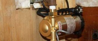
In addition to general-purpose electrical devices (starters, intermediate relays, switches, etc.), when automating pumping units, special monitoring and control devices are used, for example, pressure switches, level control relays, jet relays, etc.
Level control relays regulate the operation of pump starters and valves to control fluid levels. Such devices are capable of maintaining a set water level in containers.
Modern liquid level control relays are electronic devices, most often modular, that receive signals from sensors, process them according to a specific algorithm and switch actuators connected to the relay output contacts (solenoid valves, pump motors).
Since the maximum switched current of the output circuits of electronic level control relays usually does not exceed 10 A, magnetic starters must be used to switch powerful loads. In this system, the level relay controls the starter coil, and the starter controls the actuators of the pumping unit with its power contacts.
Electronic level control relays work with electrode and float sensors, pressure gauges, radioactive sensors, etc.
Electrode level sensor
Used to monitor the level of electrically conductive liquids. Operating principle: control of water resistance between single-pole immersed electrodes, for which alternating voltage is used.
Consists of one small electrode and two long electrodes mounted in a terminal box. One small electrode is the contact of the upper water level, and the long ones are the contact of the lower water level. The sensor is connected to the level relay and to the pump motor control circuit using wires.
If water comes into contact with the small electrode, the pump starter is turned off. When the level drops to the long electrodes, the pump turns on.
Float level sensor
Used to control the water level in non-aggressive liquids. A float is immersed in an open container, suspended on a flexible cable and balanced with a load. Two switching supports are attached to the cable, with the help of which, at maximum water levels in the tank, the rocker arm of the contact device rotates. This rocker closes contacts that turn the pump motor on or off.
In the case of a closed container, the float is connected by its lever to the axis of the lever. An axis with a certain seal is passed into the space through the wall of the housing where the contact part of the sensor is located. The wires from the contacts are routed through the wall of the container.
In most cases, suitable sensors are included with a level switch. After purchasing such a set, the consumer only needs to connect and configure everything correctly.
The following are devices that are characterized by high reliability and excellent performance parameters.
Relay RKU-1M - controls the liquid level and is used in automatic control of filling and draining containers and in protection circuits. Main characteristics: maximum switching power 3.5 W, power supply 220V, number of sensors 3, one switching contact, maximum distance from sensor to relay 100 m.
Rice. 1. Relay RKU-1M
Rice. 2. Connection diagram of the pump to RKU-1M
Water level switch ROS-301 – controls three levels of electrically conductive liquids through three independent channels in one or different containers.
Rice. 3. Relay ROS-301
Single-level water level relay PZ-828 – has adjustable sensitivity, voltage – 230V, maximum current of output circuits – 16A. The device uses a changeover contact.
Rice. 4. Relay PZ-828
Rice. 5. Connection diagrams for the PZ-828 relay (directly to the load and through a magnetic starter)
The two-level relay PZ-829 is an automatic machine with adjustable sensitivity. This electronic device can control the presence of liquid at two levels.
Three-level relay PZ-830 – controls and maintains the set level of conductive liquid by controlling the electric motor of the pumping unit. A three-level automatic machine is capable of monitoring the presence of liquid at three levels, where the third level is emergency.
Rice. 6. Connection diagram for four-level level relay PZ-830
Four-level relay PZ-832 – controls and maintains the level of conductive liquids in tanks, water towers, swimming pools, etc. by controlling electric motors of pumps.
Liquid level relay equipped with three sensors EBR-1 is an electronic modular relay with a maximum distance between sensors of 100 meters. It can be used for public reservoirs (controlling the filling and draining of a container or well). Sensors supplied with a liquid level control relay are connected to the mechanism.
Main characteristics: power 3.5 VA, three sensors, maximum sensitivity 50 KOhm, power supply 230 V, operating temperature -100C – +450C, IP20 protection.
Level relay EBR-1
Relay equipped with six sensors EBR-2 is a specially designed modular monitoring relay used in wells and tanks. Also, this relay has many settings, notification when the minimum and maximum water levels are reached, the sensors are highly sensitive to the electrical conductivity of the liquid.
The kit includes six sensors. Due to its cost, this monitoring relay is an ideal option for modern water level monitoring.
Device, circuit and connection of the intermediate relay
Hello, dear readers of the site sesaga.ru. Intermediate electromagnetic relays are used in many electronic and electrical circuits and are designed for switching electrical circuits. They are used to amplify and transform electrical signals; remembering information and programming; distribution of electrical energy and control of the operation of individual elements, devices and equipment units; coupling of elements and devices of radio-electronic equipment operating at different voltage levels and operating principles; in alarm, automation, protection circuits, etc.
An intermediate electromagnetic relay is an electromechanical device that can switch electrical circuits and also control another electrical device. Electromagnetic relays are divided into permanent
and
alternating current
.
The operation of an electromagnetic relay is based on the interaction of the magnetic flux of the winding and a moving steel armature, which is magnetized by this flux. The figure shows the appearance of the RP-21 type intermediate relay.
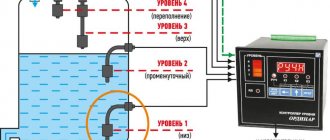
Registration of water level in a closed tank (level alarm)
Float switches are often used to indicate the level of liquid in a closed tank. The sensor contacts switch the signal lamps on the control cabinet. For these purposes, a specialized device - a level indicator - can also be used. In this case, signals from the sensors are input to the device inputs. The figure shows an example of recording the water level using the SAU-M6 level switch.
Tags: float level sensor, level relay, level switch, pump control
Relay device.
The relay is a coil
, the winding of which contains a large number of turns of insulated copper wire.
Inside the coil is a metal rod ( core
) mounted on an L-shaped plate called
a yoke
.
The coil and core form an electromagnet
, and the core, yoke and armature form
the relay's magnetic circuit
.
An anchor is located above the core and coil
, made in the form of a metal plate and held by
a return spring
.
Movable contacts
are rigidly fixed to the armature , opposite which are located corresponding pairs
of fixed contacts
. Relay contacts are designed to close and open an electrical circuit.
Sensors "Crystal"
This float level sensor for aggressive media is distinguished by its compactness. The system can withstand a maximum pressure of 3.3 bar. The meter head has a diameter of 2.3 cm. The cable entry is used with a plastic seal. The ring in this case is installed with a clamp. It is also important to note that the differential resistance of the device is at 40 degrees. It contains a spark protection barrier. The user can purchase this level sensor at a price of 2,400 rubles.
How does a relay work?
In the initial state, until voltage is applied to the relay winding, the armature, under the influence of the return spring, is at some distance from the core.
When voltage is applied, current immediately begins to flow in the relay winding and its magnetic field magnetizes the core, which, overcoming the force of the return spring, attracts the armature. At this moment, the contacts attached to the anchor, moving, close or open with the fixed contacts.
After turning off the voltage, the current in the winding disappears, the core is demagnetized, and the spring returns the armature and relay contacts to their original position.
ARS models
This sensor is most often used in reservoirs. In this case, the measuring head is used with a small diameter. According to the documentation, the load capacity of the model is 1 A. The cable entry in the device is sealed. The seal of the level sensor is made entirely of plastic. The switching differential of the device is at 45 degrees.
The body of the model is very compact. The output contact is open type. The model does not have a spark protection barrier. The maximum pressure indicated by the water level sensors in the tank (float type) can withstand 3 bar. You can purchase it at a price of 2 thousand rubles.
Relay contacts.
Depending on the design features, the intermediate relay contacts are normally open
(closing),
normally closed
(breaking) or
changeover
.
3.1. Normally open contacts.
As long as the supply voltage is not applied to the relay coil, its normally open contacts are always open
.
When voltage is applied, the relay is activated and its contacts close
, completing the electrical circuit. The pictures below show the operation of a normally open contact.
3.2. Normally closed contacts.
Normally closed contacts work the other way around: as long as the relay is de-energized, they are always closed
.
When voltage is applied, the relay is activated and its contacts open
, breaking the electrical circuit. The pictures show the operation of a normally open contact.
3.3. Changeover contacts.
For changeover contacts with a de-energized coil, the average
the contact attached to the anchor is
common
and closed with one of the fixed contacts. When the relay is triggered, the middle contact, together with the armature, moves towards the other fixed contact and closes with it, while simultaneously breaking the connection with the first fixed contact. The pictures below show the operation of a changeover contact.
Many relays have not one, but several contact groups, which makes it possible to control several electrical circuits simultaneously.
There are special requirements for intermediate relay contacts. They must have low contact resistance, high wear resistance, low tendency to weld, high electrical conductivity and long service life.
During operation, the contacts with their current-carrying surfaces are pressed against each other with a certain force created by the return spring. The current-carrying surface of a contact in contact with the current-carrying surface of another contact is called the contact surface
, and the place where the current passes from one contact surface to another is called
electrical contact
.
The contact of two surfaces does not occur over the entire apparent area, but only in separate areas, since even with the most careful treatment of the contact surface, microscopic tubercles and roughness will still remain on it. Therefore, the total contact area
will depend on the material, the quality of the contact surfaces and the compression force. The figure shows the contact surfaces of the upper and lower contacts in a greatly enlarged view.
At the point where current passes from one contact to another, electrical resistance occurs, which is called contact resistance
. The magnitude of the contact resistance is significantly influenced by the magnitude of the contact pressure, as well as the resistance of the oxide and sulfide films covering the contacts, since they are poor conductors.
During long-term operation, the contact surfaces wear out and can become covered with soot deposits, oxide films, dust, and non-conducting particles. Contact wear can also be caused by mechanical, chemical and electrical factors.
Mechanical wear occurs when contact surfaces slide and impact. However, the main cause of contact destruction is electrical discharges
, arising when opening and closing circuits, especially DC circuits with an inductive load. At the moment of opening and closing, the phenomena of melting, evaporation and softening of the contact material, as well as the transfer of metal from one contact to another, occur on the contact surfaces.
Silver, alloys of hard and refractory metals (tungsten, rhenium, molybdenum) and metal-ceramic compositions are used as materials for relay contacts. The most widely used material is silver, which has low contact resistance, high electrical conductivity, good technological properties and relatively low cost.
It should be remembered that there are no absolutely reliable contacts, therefore, to increase their reliability, parallel and serial connection of contacts is used: when connected in series, the contacts can break a large current, and parallel connection increases the reliability of the electrical circuit.
Float level gauges and alarms, float level switch
Float level measuring instruments are widely used due to the simplicity of their design and fairly high accuracy.
The main elements of float level measuring instruments are a float, a transmission mechanism and a reading or recording device. When the liquid level changes, the float moves with it over the entire measuring range.
There are many design solutions for converters. Basically, these are level switches with a mechanical connection between a float and a measuring circuit, and the connection can be either flexible (thread, cable, tape) or rigid (lever, rack). When using float level gauges with a flexible coupling, it is extremely difficult to measure the level in vessels operating under pressure or requiring tightness, since when the flexible element is removed through the stuffing box, significant resistance arises, leading to level measurement errors. In these cases, it is preferable to use level gauges with magnetic coupling between the float and the measuring circuit.
To measure the level of homogeneous, non-precipitating, non-crystallizing liquids in various technological tanks, a float level switch and electrical level switches are used.
The principle of operation of the level switch (Fig. 1) is based on the dependence of the position of the float located in the measured medium on its level. When the liquid level changes, the position of the float 5, connected to a permanent magnet 4, changes. A similar permanent magnet 3 is housed in a sealed aluminum housing. Thanks to the magnetic connection of magnets oriented with like poles relative to each other, this movement controls the contact device 2 through the sealed wall. When the liquid reaches the upper limit position, the normally closed contact opens and the normally open contact closes.
Structurally, the alarm device consists of a float 5 with a magnet 4 fixed on the axis of the bracket 6, placed in a cast housing 1. For the level alarm (see Fig. 1, b), the magnet 4 and the float 5 interact with each other using stops 7 (magnet and float are independently mounted on axis 8, but the magnet is rigidly connected to brackets 9). In the level switch (see Fig. 1, c), the float 5 interacts with the magnet 4 using height-adjustable strips 10 located on a flexible cable stretched by counterweights 11. The operation error does not exceed ±3 mm.
Electrical diagram of the relay.
On circuit diagrams, the coil of an electromagnetic relay is depicted as a rectangle and the letter “K” with the serial number of the relay in the circuit. Relay contacts are designated by the same letter, but with two numbers separated by a dot: the first number indicates the serial number of the relay, and the second indicates the serial number of the contact group of this relay. If in the diagram the relay contacts are located next to the coil, then they are connected by a dashed line.
Remember.
In the diagrams, the relay contacts are shown in a state when voltage has not yet been applied to it.
The manufacturer indicates the electrical circuit and numbering of the relay terminals on the cover covering the working part of the relay.
The figure shows that the coil terminals are indicated by numbers 10
and
11
, and that the relay has three groups of contacts:
7 - 1 - 4 8 - 2 - 5 9 - 3 - 6
Here, under the electrical diagram, the electrical parameters of the contacts are indicated, showing what maximum current they can pass (switch) through themselves.
The contacts of this relay switch an alternating current of no more than 5 A at a voltage of 230 V, and a direct current of no more than 5 A at a voltage of 24 V. If more than the specified current is passed through the contacts, they will very soon fail.
On some types of relays, the manufacturer additionally numbers the terminals on the connection side, which is very convenient.
For ease of operation, replacement and installation of relays, special blocks are used that are installed on a standard DIN rail. The blocks have holes for relay contacts and screw contacts for connecting external conductors. Screw contacts have contact numbering that matches the relay contact numbering.
Also on the relay coils the type of current and operating voltage of the relay winding are indicated.
We’ll finish here for now, and in the second part we’ll look at the main parameters
and
connecting electromagnetic relays
, where we will analyze the operation of the relay using examples of simple circuits.
See you on the pages of the site. Good luck!
1. I. G. Iglovsky, G. V. Vladimirov - “Handbook of electromagnetic relays”, L., Energy, 1975 2. M. T. Levchenko, P. D. Chernyaev - “Intermediate and indicating relays in devices relay protection and automation", Energy, Moscow, 1968, (B-ka electrician, issue 255). 3. V. G. Borisov, “Young radio amateur”, Moscow, “Radio and Communications” 1992
Rating
(No ratings yet)
Comments0 Share:
Loading …
Similar materials
Float maintenance and repair
Subject to the operating rules, the float to turn on the pump will work for a long time and properly. If the element is used in conditions of working with clean water, then it does not require special maintenance. If the float is used when working with dirty water and a large amount of solid fractions, then it, like the entire system, must be washed under running clean water. This must be done at least once a month. This will prevent the part from sticking to the pressure pipe or pump.
If water gets inside the float, its contacts burn, or the integrity of the cable insulation is damaged, all faulty elements must be replaced, since they cannot be repaired. If the electronic float itself is completely out of order, then it must be changed at special service centers.
Nivelco float type sensors
This level sensor (float) is produced for wells and swimming pools. The seal of the model is made of ordinary rubber. This sensor cannot last long. However, the low cost of the product should be taken into account. If we talk about the design features of the level sensor, it is important to note that its ring is located above the clamp. In this case, the diameter of the mounting flange is 3.4 cm.
The fuel probe itself is located under the meter head. The guide post in the device is short. The switching angle of the model is 13 degrees. The load capacity indicator does not exceed 2 A. The system can withstand a maximum pressure of 3 bar. A spark protection barrier is provided in the device. The user can purchase this level sensor at a price of 2 thousand rubles.
Wilo float type devices
This level sensor (float) is mainly used in open water bodies. It is definitely not suitable for aggressive environments. The meter head has a small diameter. The output cable of the device is located under the protective ring. If we talk about the parameters, it is important to note that the maximum permissible temperature is 140 degrees.
The output contact in the device is open type. The maximum pressure indicator does not exceed 2 bar. The switching angle of the level sensor is 12 degrees. The connecting cable of the model is made with a seal. The insulating plate itself is made of silicone. The shift differential is only 30 degrees. This level sensor is not suitable for swimming pools. You can purchase the device at a price of 1900 rubles.
Optima float type models
This liquid level sensor (float) is used in fire tanks and ponds. A distinctive feature of the model is the large mounting flange. The ring in this case is installed with a clamp. The diameter of the meter head is exactly 2.5 cm. The seal in the presented level sensor is made of plastic. The manufacturer does not provide a plug.
The maximum overpressure of the device is 3 kg per square meter. see. The load capacity of this level sensor does not exceed 2 A. According to the manufacturer, the degree of protection is marked IP68. You can purchase this level sensor for 2100 rubles.
Description of the Jhcool level sensor
This level sensor (float) is suitable for use in wells and swimming pools. It is very compact in size. The meter head itself is installed together with the seal. It is made entirely of rubber. The landing flange is located on a special ring. The connecting valve is located at the bottom of the structure. A plug is not provided in this case. It is also important to note that the model has one resistance contact. The load capacity of the level sensor does not exceed 1 A.
The maximum pressure indicator is at 4 bar. The presented specimen is not suitable for aggressive environments. It is also important to note that the model has a small switching angle. The minimum overpressure does not exceed 1 kg per square meter. see The connecting cable in the device is of a two-wire type. You can buy this level sensor for 1800 rubles.
Description of the Fine Tek model
These level sensors and float switches are suitable for harsh environments. The device is used not only in pits, but also in wells. The compact dimensions of the device allow it to withstand high pressure. The load capacity of the presented level sensor is at the level of 2 A.
The diameter of the meter head is exactly 2.5 cm. The cable entry of the model is installed with a special seal. According to the documentation for the device, it is made of plastic. The landing flange is used with a large diameter. It is also important to note that the device has a fuel probe. It is located immediately under the meter head. The plug for this model is made of silicone. The specified level sensor costs around 2400 rubles.
Varma model parameters
This float level sensor can be used in liquids of high density. The cable entry for the model is of a two-wire type. The diameter of the meter head is exactly 2.3 cm. The seal in the presented level sensor is made entirely of plastic. The model has an extended tube. The fuel probe of the device is located under the meter head.
The maximum permissible temperature is 230 degrees. The output contact is of a closed type. The maximum density of the liquid is 4 kg per square meter. cm. There is a guide post with a diameter of 2.3 cm. This level sensor does not have a fuel probe. The user can purchase this modification at a price of 2,700 rubles.