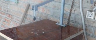
Purpose and principle of operation
Overheating of plants growing in greenhouses can negate all the work that went into growing them. To avoid such situations, greenhouse premises must be regularly ventilated. It is especially important to perform this procedure in cases where the temperature inside the greenhouse reaches critical values. If you do not use a device such as a thermal drive for greenhouses (or a hydraulic cylinder), then constantly monitoring the temperature inside such rooms and ventilating the greenhouse yourself can take a lot of time, which could be spent more profitably. That is why any greenhouse owner who wants to make its maintenance process more efficient and less labor-intensive is seriously thinking about how to make a device for automatically ventilating greenhouses with their own hands.
The operating principle of a hydraulic cylinder for greenhouses is quite simple and is based on the law of physics, according to which a liquid, when heated, expands in its volume, and when cooled, it contracts, returning to its original state. Thus, if you place a liquid in a sealed cylinder equipped with a piston with a rod, then when heated it will begin to expand, which will lead to movement of the piston and, accordingly, the rod, which is rigidly connected to it.
The operating principle of the automatic greenhouse window opening system
Hydraulic cylinders for greenhouses, installed on the windows of such premises, operate according to the above scheme. As the air temperature inside the greenhouse increases, the liquid inside the hydraulic cylinder begins to expand and pushes out the piston of the device, imparting movement to the rod and the window frame connected to it, which will begin to open. When the air temperature in the greenhouse decreases, the system will begin to work in the opposite direction: the liquid will begin to compress and return to its original state, which will lead to the lowering of the piston with the rod and, accordingly, the closing of the greenhouse window frame.
How can such a simple system ensure the opening and closing of greenhouse window frames? Calculations show (and this is confirmed by practice) that a hydraulic cylinder with a diameter of 50–55 mm and a length of 50 cm with 800 grams of working fluid, which can be used as waste technical oil, is capable of automatically opening a window frame that weighs 10 kg.
Hydraulic cylinders can also be used to open greenhouse doors
Advantages and disadvantages
Among the advantages that a hydraulic cylinder used to provide ventilation of greenhouse premises in automatic mode has, the following should be highlighted.
- To operate such a device, it does not need to be connected to a power supply.
- A simple design scheme makes it quite easy to make a hydraulic cylinder for a greenhouse with your own hands.
- Such a device does not require constant maintenance.
An automatic ventilation system based on a hydraulic cylinder, despite some disadvantages, is quite often used in personal greenhouses
Naturally, such a device for automatically ventilating greenhouses also has disadvantages.
- When installing such a device on a window frame that rotates on a vertical axis, it is necessary to additionally use a return spring, since such a frame will not lower under its own weight when the volume of working fluid in the hydraulic cylinder decreases.
- If the air temperature drops sharply outside the greenhouse, the hydraulic cylinder will not close the window frame at the same moment; this will happen only after 15–20 minutes, when the oil in its working chamber has cooled.
Hydraulic cylinder manufacturing options
When thinking about how to make a hydraulic cylinder for ventilating a greenhouse with your own hands, you can easily find a drawing of such a device on the Internet and even watch a video describing in detail the manufacturing process of such a device. To create a hydraulic cylinder, you can use parts from technical devices that are no longer working. Thus, by spending a minimum of financial resources, you can equip your greenhouse with automatic window openers, which will allow you not to worry about the fact that the greenhouse plants are not provided with the proper temperature conditions.
We list the most popular options for self-manufacturing a hydraulic cylinder for ventilating a greenhouse:
- from old car parts;
- from a jack or gas lift of a computer chair;
- from improvised means.
Homemade greenhouse ventilator from car gas lift
From old car parts
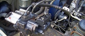
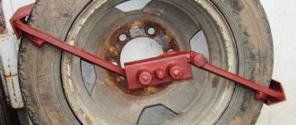
An automatic ventilator for a greenhouse, as mentioned above, can be made from unused automobile spare parts. For such purposes, in particular, a pneumatic cylinder is used, installed in the rear door retention mechanisms of cars of many brands (Niva, Moskvich, VAZ-2108, etc.).
Before you start making such a device, which is used to lift window frames that rotate on a horizontal axis, you need to find its drawing on the Internet, which will not be a big problem.
Scheme of an automatic ventilator from a car pneumatic cylinder
To make a greenhouse hydraulic cylinder from the shock absorber of the rear doors of cars, capable of opening even fairly heavy window frames, prepare:
- the pneumatic cylinder itself (you will need a container and a rod for the hydraulic cylinder);
- epoxy adhesive;
- electric drill and a set of plumbing tools.
The procedure for performing work on the manufacture of a greenhouse hydraulic cylinder is as follows.
- A small diameter hole is drilled in the bottom part of the pneumatic cylinder. When performing this procedure, you should wear safety glasses to prevent small chips flying from the drilling area from getting into your eyes.
- The resulting hole is drilled to a diameter of 9 mm.
- The piston of the pneumatic cylinder is removed from its cavity, the walls of which are thoroughly degreased.
- The upper part of the piston is lubricated with oil, after which it is placed in the cylinder and lowered to a mark located at a level of 3–3.5 cm from the bottom of its internal cavity.
- The cylinder, together with the piston placed in it, is carefully clamped in a vice so that its bottom part is located with the hole facing up.
- Epoxy resin is poured into the cylinder cavity through a pre-made hole. This is done in order to form an adhesive plug in its bottom part. The oil with which it was previously lubricated will not allow the piston to stick to such a plug.
- After the epoxy resin has completely hardened, the piston is removed from the cylinder cavity.
- The glue plug is drilled through a hole in the bottom of the cylinder with a drill of the same diameter. After this, an M10 thread is cut into the resulting hole in increments of 1.25 mm.
- The upper part of the container is closed with a plug with a hole in which the rod for the hydraulic cylinder will move.
- The finished hydraulic piston is fixed under the greenhouse window in such a way that its rod, which may have to be shortened, opens the transom when extended.
Assembly of the structure
You can create a hydraulic cylinder for a greenhouse from suitable available parts. For example, car parts are a good remedy.
A gas piston will be an excellent basis for constructing a ventilation device inside a greenhouse.
At the same time, it is important to determine the location of its installation after assembly, and the principle of operation of the product is based on some expansion of the liquid at the moment when the temperature in a greenhouse made of high-quality polycarbonate rises.
To carry out a complex of works, you will need such components as a hydraulic cylinder from trucks, which are used to lift the body, or thrust devices. You also need epoxy glue and a drill to create a machine for a greenhouse with your own hands. The assembly process is carried out independently and includes the following steps:
You can create a structure for greenhouse ventilation from the base of an office chair that has height adjustment. You can also make an automatic machine for ventilating a greenhouse entirely from available materials. In any case, it is important to follow the technology and take into account the principle of operation that distinguishes the hydraulic cylinder for a greenhouse with your own hands. A practical, convenient and effective device will provide good ventilation and the ventilation process in a polycarbonate greenhouse.
Double acting pneumatic cylinders
In double-acting pneumatic cylinders, compressed air is supplied both to the piston cavity and to the rod cavity.
Pneumatic cylinder with one-way rod
Double-acting pneumatic cylinders with a single-sided rod are most widely used due to their simplicity of design, versatility, ability to regulate forward and reverse speed, and compactness.
Pneumatic cylinder design
In the presented design, the lids and sleeve are tightened with 14 anchors (studs) with 15 nuts.
Basic Concepts
The schematic diagram of a pneumatic cylinder is shown in the figure.
When describing the operation of a pneumatic cylinder, the following terms are most often used.
The piston cavity is the chamber between the piston and the rear cover.
The rod cavity is the space between the piston and the front cover.
Direct stroke - movement of the piston when pressure is applied to the piston cavity.
Reverse stroke is the movement of the piston when emptying the piston cavity.
The active chamber is a pressure chamber.
Dead volume is the space remaining between the front and rear covers and at the extreme positions of the piston.
Effective area is the area of the piston that is affected by compressed air pressure.
Operating principle
Compressed air from a compressor or other source is supplied to the piston cavity of the pneumatic cylinder, the rod cavity at this moment is connected to the atmosphere using a distributor, the pressure of the compressed air acts on the piston, causing it to move until it rests against the front cover. The pneumatic cylinder makes a straight stroke, its rod extends. The force developed by the pneumatic cylinder during forward stroke can be calculated using the relationship:
roboforum.ru
Technical forum on robotics.
- Forum list ‹ Workshop ‹ Ideas ‹ CRAZY PROJECTs
- Change font size
- print version
- Shop
- Rules
- Wiki
- FAQ
- Registration
- Entrance
Re: pneumatic cylinder from gas shock absorber
by Plastilinstyle » Sep 13, 2012, 11:36 pm
When you drill, it will whine.
Added after 1 minute 31 seconds: and somehow this plastic “connection” is not there yet.
Re: pneumatic cylinder from gas shock absorber
by robovan » Sep 13, 2012 11:47 pm
Re: pneumatic cylinder from gas shock absorber
by Plastilinstyle » Sep 14, 2012, 00:02
Re: pneumatic cylinder from gas shock absorber
by robovan » Sep 14, 2012 00:04
Re: pneumatic cylinder from gas shock absorber
by Plastilinstyle » Sep 14, 2012, 00:09
Re: pneumatic cylinder from gas shock absorber
gosubl » Sep 14, 2012, 00:11
Re: pneumatic cylinder from gas shock absorber
by Plastilinstyle » Sep 14, 2012, 00:15
Re: pneumatic cylinder from gas shock absorber
gosubl » Sep 14, 2012, 00:40
Re: pneumatic cylinder from gas shock absorber
by Plastilinstyle » Sep 14, 2012, 00:43
Re: pneumatic cylinder from gas shock absorber
by robovan » Sep 14, 2012 01:11 am
Re: pneumatic cylinder from gas shock absorber
setar » Sep 14, 2012 05:37 am
think first and then drill, there are from 50 to 150 atmospheres driven in there. besides, first calculate at what speed the hose will fly out from the bicycle when you apply pressure there.
Added after 5 minutes 40 seconds: in general the idea is correct, but they need to be discharged using a device that will not allow the drill to fly far, I dismantled such a drill using a drilling machine through a felt boot.
Re: pneumatic cylinder from gas shock absorber
by robovan » Sep 14, 2012 12:56 pm
Re: pneumatic cylinder from gas shock absorber
by Plastilinstyle » Sep 14, 2012, 1:29 pm
Re: pneumatic cylinder from gas shock absorber
by Dmitry__ » Sep 14, 2012, 01:29 pm
Single acting pneumatic cylinders
In single-acting pneumatic cylinders, compressed air is supplied to only one cavity; the return stroke is carried out due to a spring, or under the influence of external influence.
Spring return pneumatic cylinder
The illustration shows a single-acting pneumatic cylinder with spring return. The forward stroke is carried out due to the energy of compressed air supplied to the cylinder cavity. To carry out the reverse stroke, a compression or extension spring can be used. The spring can be installed in both the rod and piston chambers.
Plunger Pneumatic Cylinder
In pneumatic cylinders of this type, compressed air acts on the plunger, causing it to extend, overcoming external influences. The force developed by the plunger pneumatic cylinder during direct operation can be calculated using the formula:
- where p is the compressed air pressure
- D - plunger diameter
The reverse stroke is carried out under the influence of external forces. The plunger can be manufactured with or without an external stop (as shown in the figure).
Single acting telescopic pneumatic cylinder
In a single-acting telescopic cylinder, compressed air is supplied through the rear cover, and the sections are pulled out sequentially. The return stroke of the rods is carried out under the action
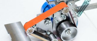
Do-it-yourself pneumatic press: making a pneumatic press from an office chair gas lift
To perform many jobs in industrial and home workshops, it is very convenient to use a pneumatic press, which, by developing sufficient force, greatly facilitates the process of carrying out many technical procedures. In particular, using such equipment, it is possible to bend metal products, carry out die-cutting operations and hammerless riveting, and use the force that such a press creates for gluing wood products and hot stamping. It is very convenient that you can make a simple but quite effective pneumatic press with your own hands, and this does not require expensive consumables or special equipment.
Homemade pneumatic press from an office chair gas piston
Preparation of components
Before you start making your own pneumatic press, you should understand the principle of its operation. If hydraulic presses are driven by a hydraulic pump, then in pneumatic press equipment a device that produces compressed air is used for these purposes. A compressor or air pump can be used as such a device. Compressed air of a certain pressure is supplied to a pneumatic cylinder or to a membrane-spring pneumatic actuator, on the output rod of which the required pressure is created.
The gas lift device for an office chair allows it to be used as a pneumatic pusher
It should be borne in mind that pneumatic presses, when compared with hydraulic ones, create less pressure, but in many cases it is sufficient to perform certain technological operations.
So, in order to make a simple pneumatic press, you need to prepare:
- pneumatic shock absorber (such shock absorbers are installed on office and computer chairs);
- air pump or small compressor;
- threaded fitting with a diameter of 3 mm;
- connecting hose.
To easily remove the gas lift from the crosspiece, apply penetrating lubricant, remove the locking key and carefully knock the part out of the cone joint.
Assembling the shock absorber
We put on a bump stop, if it is not there, then we go to a car store and buy a Zhiguli silent block. It should fit almost perfectly onto the shaft. If you have the opportunity to overpay a little, buy a polyurethane silent block (yellow), it will last you much longer than a regular rubber silent block made of non-oil-resistant rubber. Trim it if necessary.
A regular silent block can be used as a bump stop
Then we put the assembled bushing with the oil seal on the rod, put on the bypass piston and tighten the nut. Don't forget to roll the threads. There were cases when our “homemade workers” arrived with rods in their hands.
Assembling the shock absorber rod
If there is mechanical damage or corrosion on the shock absorber rod, our specialists can make a new rod for you.
We install the shock absorber vertically in a vice. We prepare a container that we place under the shock absorber and into which excess oil will be drained as the shock absorber is assembled. Pour oil into any of the pipes and wait until the air bubbles disappear. We align the two reservoirs according to the amount of oil so that the compensation tank is exactly half filled with oil.
Pour oil into the shock absorber and wait until the air bubbles disappear
We take a gas injection tank and install it in the appropriate tank
Installing a gas pumping tank
Installing a gas injection tank
If you have any questions or difficulties in assembling the shock absorber, our company’s specialists are ready to help you.
We take our rubber pneumatic membrane and screw the nipple into it. Before installing the membrane in the shock absorber, check it for leaks. We insert our membrane into the body and secure it with a retaining ring.
We screw the nipple into the rubber pneumatic membrane and insert it into the shock absorber body
We fix the membrane in the shock absorber body using a retaining ring
We take the shock absorber rod and slowly insert it into the body, then insert the bushing with the oil seal and also fix it with a locking ring.
Installing the rod into the body
After assembling the hydraulic part of the shock absorber, we can pump gas into the compensation tank. This way we can check the shock absorber for leaks. During gas pumping, the shock absorber rod must come out of the housing under pressure. If there are no oil smudges or oil stains on the rod, then the shock absorber is assembled correctly and is ready for installation on a motor vehicle.
Manufacturing process
The manufacturing process of the press, the basis of which will be the pneumatic shock absorber from the chair, is carried out according to the following algorithm.
- On the side of the pneumatic shock absorber from the chair, using a marker, mark the place where the threaded fitting will be installed.
- At the marked location, a hole of the appropriate diameter is made, in which a thread is cut to install the fitting.
- The fitting is screwed into the prepared hole, for which it is better to use sealing tape.
- A hose is placed on the upper part of the fitting; for more reliable fixation it is better to use a clamp of the appropriate size.
- The second end of the hose is connected to the outlet fitting of the air pump or compressor and is also secured with a clamp.
Marking the installation location of the fitting
Now that the pneumatic press is fully assembled, you can test it in operation, for which you just need to turn on the air pump or compressor. Once air from the air supply device begins to flow into the inside of the air spring, the output rod should begin to move. If such a movement occurs, then this indicates the correctness of the actions performed.
Checking the functionality of the mechanism
To make a pneumatic table press more convenient and efficient to use, a metal circle of small diameter can be fixed at the working end of its rod, which, acting on the workpiece, will create pressure over a larger area.
The press of the design proposed above can be easily modified if necessary. In the same form, it can be used to perform simple bending and die-cutting operations. If desired, the resulting structure can be fixed on the base of the pneumatic chair itself, where there are already mounting holes for it. By doing this, you will get a more convenient device to use, installed on a reliable base.
Types of shock absorbers by type of gas-filled tanks
There are several types of gas-filled tanks. They look almost the same, but their internal design is different.
Option 1 is a compensation tank with a rubber bulb filled with nitrogen up to 10 bar. Such shock absorbers are usually installed in pairs.
Option 2 is a compensation tank with a floating piston, into which nitrogen is charged up to 15 bar. Such shock absorbers are usually found on enduro, motocross motorcycles, snowmobiles and ATVs.
Option 3 is a compensation tank with a floating piston, into which nitrogen is filled up to 15 bar; the tank is connected to the shock absorber with a flexible hose. Such shock absorbers are usually found on enduro, motocross motorcycles, snowmobiles and ATVs.
Next, we lift the top cover of the shock absorber and fix it on the rod with an ordinary clothespin or an office paper clip (depending on what is convenient for you and who has what you have). You can even use a regular rubber band or plastic clamp. - Under the cover there is a retaining ring and a bushing in which there is an oil seal and a bronze guide.
Under the cover there is a retaining ring and a bushing in which there is an oil seal and a bronze guide
In order to pull out the retaining ring, you need to push the sleeve down.
Push the bushing down and remove the retaining ring
That's it, we disassembled the shock absorber. Here's what we have on the table:
1 - Shock absorber body with a barrel, 2 - Shock absorber rod with bushing and piston, 3 - Two retaining rings 4. Reservoir for gas injection, 5 - Drilled cover, 6 - Torn silent block.
In order to remove the sleeve in which the oil seal is located, you need to unscrew the nut that holds the piston. It often happens that the thread behind the nut is flared. In this case, we use either a file, or a sharpener, or a grinder with a grinding wheel. But before removing the rolling, if there is one, be sure to wrap the piston with paper tape. This type of tape is hard and will save our piston from dirt and possible mechanical damage. In our case, the thread was not rolled, so we simply unscrew the nut. We take a plastic clamp and place it on the thread. We put the entire piston set on the clamp and fasten it. By disassembling the piston this way, you will never get the piston membranes mixed up or lost, and you can conveniently wash and blow it out.
Shock absorber piston assembly (piston kit)
The shock absorber piston assembly is put on a plastic clamp - the parts of the piston assembly will not get mixed up!
When the entire shock absorber is disassembled, it is strongly recommended to wash it in kerosene or gasoline and wipe it with a rag or paper towel, i.e. any suitable material that does not produce lint and does not fall apart into small threads.
The shock absorber has been disassembled and all parts have been thoroughly washed!
How to make a functional pneumatic press
As mentioned above, pneumatic presses can be used for hot stamping, as well as for veneering any wood materials (natural solid wood, chipboard, MDF, etc.). However, to solve such problems, not an ordinary, but a hot pneumatic press is used, which you can also make yourself. The main difference between this press and a conventional type device is that its working part, which exerts pressure on the product being processed, must be heated to a certain temperature.
Heating will be done using heating elements
In order to ensure heating of the working body of a pneumatic press, electric heating elements must be built into the latter, and the working body itself must be made of aluminum to ensure better thermal conductivity. The design of a pneumatic hot press is necessarily complemented by an electrical circuit consisting of two independent parts:
- an electronic unit that is responsible for turning on and heating electric heating elements (the main element of such a unit is a temperature controller that allows it to be maintained with an accuracy of half a degree);
- a block that will provide control of the air valve itself (thanks to the presence of such a block, it is possible not only to control the process of supplying the working element to the surface of the workpiece (as well as removal from it), but also to regulate the holding time of the press in a compressed state).
Thermostat with solid state relay output
Electrical circuit of a press with heating elements
Using such a press with various working attachments, you can solve many practical problems, which, in particular, include:
- performing hot stamping on leather products (shoes, bags, etc.);
- hot gluing of shoe elements;
- veneering wood products;
- design of book covers made of leather or leatherette.
In conclusion, another version of a heated press for cladding furniture panels, which uses elements of an electric heated floor.
Operating principle of hydraulic cylinder
A simple example of a hydraulic cylinder is a factory automatic system that can create ventilation inside a greenhouse. The operation of such a device is based on the movement of a piston, which begins to work due to the expansion of the liquid in the cylinder under the influence of the sun. The piston a very important part that affects many things.
When the temperature drops, the hydraulic cylinder for greenhouses closes the window, because the liquid returns to its original state with the smallest volume.
A hydraulic cylinder is a universal device that you need to pay handsomely for.
In addition, there are different greenhouse designs that require machines with unique characteristics. For example, you need to lift a massive window in a greenhouse, then you will need a stronger hydraulic cylinder for greenhouses. It is better to make such a device yourself.
When designing a hydraulic cylinder, you can make your own additions. It is important to know that the glued foil speeds up the heating of the device and this improves the process of opening the window.
Assembly of the structure
You can create a hydraulic cylinder for a greenhouse from suitable available parts. For example, car parts are a good remedy.
A gas piston will be an excellent basis for constructing a ventilation device inside a greenhouse.
At the same time, it is important to determine the location of its installation after assembly, and the principle of operation of the product is based on some expansion of the liquid at the moment when the temperature in a greenhouse made of high-quality polycarbonate rises.
To carry out a complex of works, you will need such components as a hydraulic cylinder from trucks, which are used to lift the body, or thrust devices. You also need epoxy glue and a drill to create a machine for a greenhouse with your own hands. The assembly process is carried out independently and includes the following steps:
- All manipulations are best done with safety glasses. A small hole should be drilled in the bottom of the container, and then enlarged with a large drill to 9 mm. Next, you should press on the rod, which is located at a distance of about 30-35 mm from the hole;
- After this, degrease the cavity and dry it thoroughly. Prepare the adhesive composition for work. For comfortable operation, the container should be fixed. Then the piston is carefully lubricated with oil, but it is impossible not to touch the clean walls of the vessel;
- Next, glue is poured into the hole, that is, an adhesive plug is created. After the adhesive composition has thoroughly dried, you should move the piston, and to do this you need to pull the rod. Next, a hole with a diameter of 9 mm is drilled in place of the glue plug, then a thread of 1.25 pitches is cut. The structure is then attached under the window so that the retractable rod lifts the window element.
You can create a structure for greenhouse ventilation from the base of an office chair that has height adjustment. You can also make an automatic machine for ventilating a greenhouse entirely from available materials. In any case, it is important to follow the technology and take into account the principle of operation that distinguishes the hydraulic cylinder for a greenhouse with your own hands. A practical, convenient and effective device will provide good ventilation and the ventilation process in a polycarbonate greenhouse.
Stages of creating a device
To create a hydraulic cylinder, you can use a pneumatic shock absorber from a car. Typically the shock absorber is located on the hood or tailgate. The shock absorber should not have unique characteristics, the main thing is that there is pressure in the mechanism. The pressure can be checked using the operating rod.
A hydraulic cylinder made from a shock absorber can operate for several years without failure. Creation stages:
- You need to find a ball at the end of the cylinder and cut it so that as much of the holder length remains as possible.
- Then the cylinder needs to be clamped using a vice, but do this through the ends, then the working mechanism will not be damaged.
- In a well-fixed cylinder you need to make a 3 mm hole with a drill.
- After creating a hole, air will begin to escape from the hemp due to pressure.
- A small splash may occur and then there is a risk of shavings getting into your eyes, so it is better to wear glasses or a special mask in advance. After creating the thread in the hemp, the indoor hydraulic cylinder will be ready.
- Next, a thread is formed on the hemp. Most often, operations are carried out only on the outer surfaces of the shock absorber, so there is no need to penetrate inside.
Making a fluid tank
The pneumatic cylinder must contain a fluid reservoir; it is made from a car spare part. In our case, we will analyze the creation of a hydraulic device from a cardan. Creation stages:
- The ears of the cardan must be cut off. This action must be performed carefully and according to calculations for a specific greenhouse, after which you need to weld the end.
- At the other end you need to make two holes. The first is necessary for connection, and the second to create proper air release.
- The most difficult stage in creating a device is cutting the thread. After all, any violation of symmetry can spoil the part and even break it. If you are going to use a large tank, then it is advisable to fill the excess space with metal parts.
Disassembling the shock absorber
We begin repairing the shock absorber by removing the spring. We take the most common grips. We throw them on the spring from both sides and clamp them one by one until the spring is compressed and the washer that secures it to the shock absorber is loosened.
A small digression: the better the tool, the easier and safer it is to work with it. If you can’t find the usual grips, you can contact the nearest service center or garage. As a last resort, the spring can be compressed using a tire changing machine, which separates the rubber part of the wheel from the disk. If you have ingenuity, everything will work out.
In our workshop, shock absorbers are spring-loaded using special equipment
We can wipe the spring and put it aside; it will only be useful to us when installing it on a repaired shock absorber.
In our workshop, when repairing shock absorbers, we use a pneumatic vice for a soft grip
You can use a regular vise and clamp the shock absorber at the bottom eye, but do not overdo it. Argon welding is not a cheap service these days.
Next, we drill a couple of holes in the lid of the compensation barrel and, using a threaded wire or a thin screwdriver, pull out the lid.
We drill a couple of holes in the cover of the compensation barrel and, using a threaded wire or a thin screwdriver, pull out the cover
Under the cover there is a fitting with a gas-filled reservoir. Before unscrewing the fitting, do not forget to measure the gas pressure in the tank, because it will have to be pumped up again.
In our workshop we use a high pressure pump to measure and pump gas
You can measure the pressure in the tank using a regular foot pump or a tire pressure gauge.
We unscrew the nipple from the fitting and release the gas.
If you have any difficulties with the manufacture or repair of the injection nozzle, you can always contact our company for help.
We place the pneumatic reservoir inside the tank and remove the retaining ring.
Now you can pull out the rubber bulb into which gas is pumped.
If you did not measure the pressure in the pneumatic reservoir before disassembling the shock absorber or there was no gas in it at all, do not be upset. The information below will help you decide and find your shock absorber type.