In addition to your high-quality X-ray machine, your radiologist should also have the skills to interpret images. Please note that you can buy X-ray film in our store. We recommend you AGFA D4, AGFA D7 and AGFA F8, as well as its analogue FOMADUX, which is certified according to the European BAM standard. The quality of the veil is 0.16, you can significantly save 20-30% on current costs. Analogues of INDUX R4, INDUX R7 and FOMADUX RX-8.
Application area
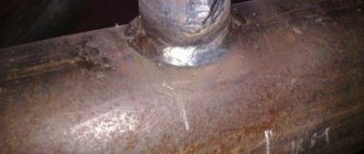
After completing the welding process and cooling of the structure, it is necessary to evaluate the quality of the work and take action if deficiencies are found. Control begins with a visual inspection. If there are defects inside the seam, it is necessary to resort to other search methods. They must be classified as indestructible. Not everyone has the required accuracy. Radiography of welded joints is one of the non-destructive methods that provides accurate information about the condition inside the weld.
In flaw detection, the ability of X-rays to penetrate deep into a considerable distance is used due to the fact that their wavelength is short. When welding, situations may arise when the wrong mode is selected or foreign objects get into the weld pool. The formation of invisible defects will reduce the strength and reliability of the entire structure, which will be able to withstand less loads than planned.
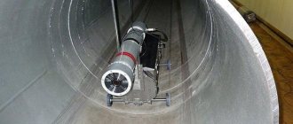
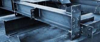
Radiographic inspection of welds requires special equipment. The costs for it are reasonable in cases where the requirements for the characteristics of the connections are high. Another option is to control structures where other methods are difficult or impossible to use. An example is radiographic testing of welded joints of pipelines.
There are laboratories specializing in the inspection of welded joints, where all the necessary equipment is available and competent professionals work. If desired, you can carry out control yourself, having mastered the necessary skills. It is possible to rent the device for this purpose. Portable devices are very popular. They are used both for pipeline inspection and for profile and sheet connections. Stationary devices can be designed individually to solve specific problems.
Radiographic testing of welded joints of pipelines is carried out in accordance with the industry regulatory document OST 36-59, which specifies all the requirements for welding of these structures. It states, in particular, that all data on the control carried out is entered into a special journal and stored for 10 years after the start of operation of the facility.
Principle of operation
Radiography is based on the ability of rays to penetrate into materials, including metals. This ability decreases with increasing metal density and increases with decreasing density. Since the density becomes lower in places with voids and cracks, this is immediately recorded by the device. If there are no defects, the metal structure remains consistently dense, and X-rays will be absorbed by the material. The higher the density, the higher the degree of absorption will be.
The main element of the apparatus for fluoroscopy of welds is the emitter, which is an X-ray tube. Its function is to generate rays and release them. Structurally, the emitter is a vacuum vessel. It contains an anode and a cathode, between which an electric potential is formed. When electrons are strongly accelerated, X-rays appear and the direction of their exit is set.
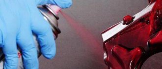
The rays passing through the metal fall on a special photosensitive film. An imprint remains on it, by which one can judge what is inside the material. The full picture will be shown by deciphering x-ray images of welded joints. If you want or need to receive information constantly, scintillators are used. This makes it possible to display the image on the monitor.
It is possible to take photographs by obtaining an x-ray. The radiograph will show a negative image of the joint. If there are inclusions or, conversely, voids, their outlines will appear in a different color. The resulting radiograph should be compared with a typical radiograph for this type of welded parts. The method allows you to accurately and quickly assess the condition of the weld.
Types of radiometric devices:
- Devices that have a fixed frequency of gamma radiation intensity fluctuations. Regular changes in the intensity of X-ray radiation create transverse stripes in the image. In this case, the root-mean-square deviations in the radiation intensity are several times higher than the statistical noise. It is possible to attenuate these fluctuations using software. For this purpose, the radiometric installation is equipped with programs that determine the spectral fraction of fluctuations for each device. Such X-ray devices are considered conditionally applicable for radiometric testing of welds and joints.
- X-ray machines with a constant potential, which have high-frequency fluctuations that are random in time. For such devices, the deviation in gamma radiation intensity is more than one percent. It is not recommended to use such devices in radiometric testing of welding structures.
- The ideal option is equipment whose radiation stability exceeds 0.5 percent, and whose fluctuation frequency is no more than 0.1 Hz. Low-frequency changes in radiation intensity of such insignificant magnitude can be easily eliminated in the image using software.
Experts recommend an X-ray software device model RPD200P, which, after appropriate modification of the power supply system, has shown that it can be successfully used in the process of high-quality radiometric monitoring.
Computer and electronic technology, which is developing at a rapid pace, opens up wide opportunities for reducing the cost and improving radiometric equipment.
The measurements carried out using the RPD200P panoramic type apparatus prove that entire radiometric complexes can be created on the basis of this type of equipment.
Preparation for control
Before starting the process, preparatory operations should be carried out. The parts of the future connection are carefully inspected. If there are contaminants and slag on them, they must be thoroughly cleaned and degreased with solvent or alcohol. This is done so that external defects during transillumination do not distort the final result.
Films are loaded into appropriate cassettes. All connections are divided into separate intervals and labeled. This is done so that you can accurately determine which image relates to a specific area of the welded seam. Cassettes and films are marked in the same order. If the seam is long, selective X-ray inspection of the welds is possible.
It is also necessary to prepare equipment intended for radiography of welds. First you need to select a suitable radiation source. The criteria are sensitivity, metal thickness and density, configuration of parts, required performance. For example, for radiographic testing of welded joints, where large defects are possible, isotopes with high energy are suitable. This will ensure a short transillumination time. The choice of film is determined by the thickness of the metal and its density. Optimal modes are set on the devices.
Thickness of metal reinforcing screens
Table 1
| Radiation source | Screen thickness, mm |
| X-ray machine with X-ray tube voltage up to 100 kV | Up to 0.02 |
| X-ray machine with a voltage on the X-ray tube over 100 to 300 kV | 0,05 — 0,09 |
| X-ray machine with X-ray tube voltage over 300 kV | 0,09 |
| 170Tm | 0,09 |
| 75Se; 192Ir | 0,09 — 0,20 |
| 137Cs | 0,20 — 0,30 |
| 60Co | 0,30 — 0,50 |
| Electron accelerator with radiation energy from 1 to 15 MeV | 0,50 — 1,00 |
Methods for charging cassettes
table 2
| Charging method | Availability of films in the cassette | |
| one | two | |
| No screens | ||
| With reinforcing metal screens | ||
| With intensifying fluorescent screens | ||
| With reinforcing metal and fluorescent screens | ||
- radiographic film;
— reinforcing metal screen;
— intensifying fluorescent screen.
Process methodology
Radiography of welds goes through several stages:
- Select a radiation source.
- Select the appropriate type of film.
- Set the equipment to optimal modes.
- Place the device inside or outside the product and turn it on.
- Start X-raying the weld.
- Take out the film and develop it.
- Perform decryption.
- Record the results in a journal in the prescribed form.
The selected cassette is secured to the product. To obtain good image sharpness and determine the reliable size of the defect, a sensitivity standard should be set on the device. The standard must be made of a material whose characteristics are close to the characteristics of the metal being welded.
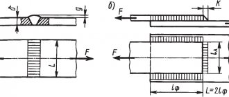
GOST 7512 specifies three preferred types of standards used for x-raying welds:
- Grooved . A plate having six grooves. They have the same width, but different depths.
- Wire . Has seven wires.
- Lamellar . A plate having holes of the required shapes and sizes.
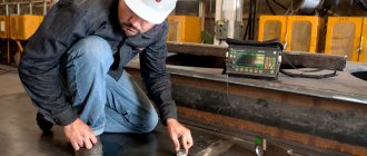
The items being tested can be placed in relation to the apparatus in two ways. If they are small and can fit indoors, the connections are placed inside the stationary apparatus. During on-site inspection, compact models of equipment are used and installed on the product.
To carry out radiographic inspection of welded joints, the seam should be placed strictly between the emitter and the photosensitive film. After turning on the emitter, X-rays will begin to pass through the metal and hit the film. In a few seconds the photo will be ready. The device is turned off. The cassette with the film is removed and given for processing and decoding. Once it is clear that the result has been obtained, the device can be removed from the product or removed from it. Otherwise, it is necessary to re-check.
Thickness of protective lead screens
| Radiation source | Screen thickness, mm |
| X-ray machine with X-ray tube voltage up to 200 kV | Up to 1.0 |
| 170Tm; 75Se | Up to 1.0 |
| X-ray machine with X-ray tube voltage exceeding 200 kV | From 1.0 to 2.0 |
| 192Ir; 137Cs; Co | From 1.0 to 2.0 |
| Electron accelerator with radiation energy from 1 to 15 MeV | St. 2.0 |
Decoding
Interpretation of radiographs is carried out in a shaded room using a negatoscope. It is a device whose purpose is to view radiographic images, including radiographs, through transmission. The negatoscope provides the ability to adjust the brightness of the lighting. If its value is too high, small defects may be missed.
After decoding, a conclusion is drawn up. Before resorting to this method, it is necessary to find out what weld defects are detected using radiographic testing. These include:
- undercuts;
- lack of penetration;
- cracks;
- pores;
- foreign inclusions;
- slags
In addition, it is possible to evaluate the amount of concavity and convexity in places where visual inspection is not possible. Abbreviations are used when writing results. So, “T” means a crack, “N” is a lack of penetration, “P” is a pore, “W” is slag, “V” is the inclusion of tungsten, Pdr is an undercut. The size of the defect is indicated next to the letters. The nature of the distribution is also taken into account.
On this basis, shortcomings are divided into groups:
- Separate.
- Chains . There are more than three defects on one line.
- Clusters . Location of at least three defects in one place.
The size of the defect is indicated in millimeters.
METROLOGICAL SUPPORT
8.1. Groove and plate sensitivity standards used for control must be subject to metrological verification upon their release and subsequent verification at least once every 5 years. When releasing these standards, the trademark of the enterprise that produced the standard and the year of issue must be applied electrochemically to the reverse side of each standard; during the next verification - the trademark or symbol of the company that carried out the verification, and the year of verification.
8.2. Wire sensitivity standards are not subject to verification, however, they must be removed from circulation if the plastic cover is damaged or traces of corrosion of the standard wires are detected during visual inspection.
8.3. Densitometers and sets of optical densities used to determine the optical density of images are subject to verification at least once a year with the obligatory execution of a document (certificate) on the verification results.
8.4. X-ray cameras are subject to verification only upon their release, with the obligatory indication in the passport (certificate) of the X-ray viewer of the maximum brightness of the illuminated field and the optical density of the image.
8.5. Measuring instruments used to determine the size of images of cracks, lack of fusion, pores and inclusions in photographs (measuring rulers and magnifying glasses) are subject to verification in accordance with the current provisions applicable to these instruments.
8.6. Non-standardized measuring instruments used to determine the size of images of cracks, lack of fusion, pores and inclusions in images (measuring templates, stencils, etc.) must be verified at least once a year with the obligatory execution of a document on the verification results.
Sec. 8. (Introduced additionally, Amendment No. 1).
Safety
For all its advantages, the method is potentially hazardous to health. Therefore, it is necessary to shield the device. The controller should not be unnecessarily in the irradiation area. Access there to unauthorized persons should be prohibited. To do this, warning signs should be posted.
When working indoors, its walls must be covered with shielding plates. The controller must be provided with a set of protective clothing. Before starting the process, it is necessary to check the serviceability of the equipment.