GOST 18877-73
GOST 18877-73 Group G23
INTERSTATE STANDARD
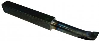
LATHE CUTS, PASSING, BENT, WITH CARBIDE ALLOY PLATES Design and dimensions Carbide-tipped bent bull-nose turning tools. Design and dimensions
ISS 25.100.10
Date of introduction 1974-07-01
ENTERED INTO EFFECT by Resolution of the State Committee of Standards of the Council of Ministers of the USSR dated June 8, 1973 N 1429 The validity period was removed by Decree of the State Standard of the USSR dated 02.20.81 N 866 INSTEAD OF GOST 6743-61 in terms of type 1; MN 575-64; MN 576-64; MN 5199-64 EDITION with Amendments No. 1, 2, approved in February 1981, November 1984 (IUS 5-81, 2-85), Amendments (IUS 6-88, IUS 4-89)
1. This standard applies to general purpose turning bent cutters with corners , , and soldered carbide plates. The standard fully complies with ST SEV 191-75.
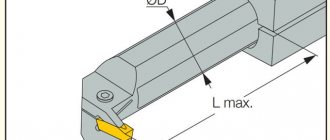
2. The design and main dimensions of the cutters must correspond to those indicated in the drawing and table.
Damn.1
________________
*Dimensions for reference.
Dimensions in mm
| Incisors | |||||||||||
| With insert angle 10° | With insert angle 0° | Tool holder | Type of plates according to GOST 25395-90 | ||||||||
| rights | left | rights | left | for mortise angle | |||||||
| Designation | Applicability | Designation | Applicability | Designation | Applicability | Designation | Applicability | ||||
| 2102-1097 | 2102-1098 | 2102-1099 | 2102-1101 | 10x10 | |||||||
| 2102-1102 | 2102-1103 | 2102-1104 | 2102-1105 | 12x12 | |||||||
| 2102-0021 | 2102-0022 | 2102-0071 | 2102-0072 | 16x10 | |||||||
| 2102-0023 | 2102-0024 | 2102-0073 | 2102-0074 | 16x12 | |||||||
| 2102-1106 | 2102-1107 | 2102-1108 | 2102-1109 | 16x16 | |||||||
| 2102-0025 | 2102-0026 | 2102-0075 | 2102-0076 | 20x12 | |||||||
| 2102-0027 | 2102-0028 | 2102-0077 | 2102-0078 | 20x16 | |||||||
| 2102-1111 | 2102-1112 | 2102-1113 | 2102-1114 | 20x20 | |||||||
| 2102-0005 | 2102-0006 | 2102-0055 | 2102-0056 | 25x16 | |||||||
| 2102-0029 | 2102-0030 | 2102-0079 | 2102-0080 | 25x20 | |||||||
| 2102-1115 | 2102-1116 | 2102-1117 | 2102-1118 | 25x25 | |||||||
| 2102-0009 | 2102-0010 | 2102-0059 | 2102-0060 | 32x20 | |||||||
| 2102-0031 | 2102-0032 | 2102-0081 | 2102-0082 | 32x25 | |||||||
| 2102-1119 | 2102-1121 | 2102-1122 | 2102-1123 | 32x32 | |||||||
| 2102-0013 | 2102-0014 | 2102-0063 | 2102-0064 | 40x25 | |||||||
| 2102-0033 | 2102-0034 | 2102-0083 | 2102-0084 | 40x32 | |||||||
| 2102-1124 | 2102-1125 | 2102-1126 | 2102-1127 | 40x40 | |||||||
| 2102-0017 | 2102-0018 | 2102-0067 | 2102-0068 | 50x32 | |||||||
| 2102-0035 | 2102-0036 | 2102-0085 | 2102-0086 | 50x40 | |||||||
| 2102-1128 | 2102-1129 | 2102-1131 | 2102-1132 | 50x50 | |||||||
An example of a symbol for a right-hand cutter with a cross-section of mm, with an angle of insertion of the plate into the rod of 0°, with a plate made of hard alloy grade T15K6:
Cutter 2102-0055 T15 K6 GOST 18877-73
1, 2. (Changed edition, Amendment No. 1, 2).
3. The insertion angle of the plate into the rod for processing cast iron and other brittle materials is 10°, for processing steel and other viscous materials - 0°. (Changed edition, Amendment No. 2).
4. (Deleted, Amendment No. 1).
5. Structural elements and geometric parameters of the cutters are indicated in Appendix 1.
6. The form of sharpening the front surface and finishing of the cutting part are indicated in Appendix 2.
7. Technical requirements - according to GOST 5688-61.
8. (Deleted, Amendment No. 2).
Damn.1
Damn.1
Table 1
Dimensions in mm
| Cutter section | Designation of plates according to GOST 25395-90 | |||
| 10x10 | 01331 | |||
| 12x12 | 10,0 | 01352 | ||
| 16x10 | 13,0 | 01331 | ||
| 12,0 | 14,0 | 01352 | ||
| 16x12 | 12,0 | 14,0 | 01352 | |
| 16x16 | 11,0 | 13,5 | 01372 | |
| 20x12 | 16,0 | 18,0 | 01352 | |
| 15,0 | 17,5 | 01372 | ||
| 20x16 | 13,5 | 17,0 | 02252 | |
| 20x20 | 13,5 | 17,0 | 01392 | |
| 25x16 | 18,5 | 22,0 | 02252 | |
| 18,5 | 22,0 | 01392 | ||
| 25x20 | 13,2 | 18,5 | 22,0 | 02272 |
| 25x25 | 17,5 | 21,5 | 01152 | |
| 32x20 | 13,0 | 26,0 | 29,0 | 02272 |
| 32x20 | 24,5 | 28,5 | 01152 | |
| 32x25 | 14,8 | 24,5 | 28,5 | 02312 |
| 32x32 | 10,5 | 23,5 | 28,0 | 01412 |
| 40x25 | 14,8 | 32,5 | 36,5 | 02312 |
| 10,5 | 31,5 | 36,0 | 01412 | |
| 40x32 | 10,4 | 32,0 | 36,0 | 01412 |
| 40x40 | 13,8 | 29,5 | 35,0 | 01432 |
| 50x32 | 15,8 | 39,5 | 45,0 | 02352 |
| 14,4 | 39,5 | 45,0 | 01432 | |
| 50x40 | 14,4 | 39,5 | 45,0 | 01432 |
| 50x50 | 19,2 | 37,5 | 44,0 | 01452 |
Damn.2
table 2
Dimensions in mm
| Cutter section | Designation of plates according to GOST 25395-90 | |||
| 10x10 | 01331 | |||
| 12x12 | 10,0 | 61352 | ||
| 16x10 | 13,0 | 01331 | ||
| 12,0 | 14,0 | 61352 | ||
| 16x12 | ||||
| 16x16 | 11,0 | 14,0 | 61372 | |
| 20x12 | 16,0 | 18,0 | 61352 | |
| 15,0 | 17,5 | 61372 | ||
| 20x16 | 13,5 | 17,0 | 62252 | |
| 20x20 | 61392 | |||
| 25x16 | 18,5 | 22,0 | 62252 | |
| 18,5 | 61392 | |||
| 25x20 | 13,2 | 18,5 | 21,5 | 62272 |
| 25x25 | 17,5 | 61152 | ||
| 32x20 | 13,0 | 26,0 | 29,0 | 62272 |
| 23,5 | 28,0 | 61152 | ||
| 32x25 | 14,8 | 24,5 | 28,5 | 62312 |
| 32x32 | 10,5 | 23,5 | 28,0 | 61412 |
| 40x25 | 14,8 | 32,5 | 36,5 | 62312 |
| 10,5 | 31,5 | 36,0 | 61412 | |
| 40x32 | 10,4 | 32,0 | 36,0 | 61412 |
| 40x40 | 13,8 | 29,5 | 35,0 | 61432 |
| 50x32 | 10,4 | 42,0 | 46,0 | 61412 |
| 39,5 | 45,0 | 61432 | ||
| 50x40 | 14,4 | 39,5 | 61432 | |
| 50x50 | 37,5 | 44,0 | 61452 |
APPENDIX 1. (Changed edition, Amendment No. 1, 2).
Classification
According to the design and principle of operation, this tool is differentiated into the following options:
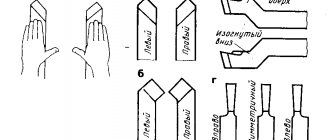
- Straight models with cutting edges parallel to the holder axis are characterized by the absence of bends. They are designed for rough processing, which involves removing a significant amount of material, often in several passes, when turning unnecessary fragments of parts.
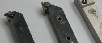
- Bent scoring cutters have a similar purpose, but are designed for processing objects of more complex shapes: bending allows you to grind hard-to-reach places, etc. The cutting edges of such models are inclined from the axis of the holder. The method of work is determined by the characteristics of the tool and the type and thickness of the material.
- Turning stop options are designed for turning objects of low rigidity. They are used for trimming edges and turning stepped surfaces. This is the most common type of instrument considered. Their cutting edges are parallel to the holder axis, however, in comparison with straight scoring cutters, they have a smaller angle.
Based on the feeding direction, these tools are classified into left-handed and right-handed.
Finally, scoring cutters are differentiated according to production technology.
- One-piece options include head and holder made from the same material.
- Composite models have elements of different composition.
Thus, bent scoring cutters with carbide cutting inserts are described by GOST 18880-73. For turning cutters equipped with super-carbide inserts, and similar scoring models, the characteristics are defined in GOST 28990-91. GOST 18871-73 defines the features of end options with high-speed steel plates. GOST 29132-91 defines the parameters of models with multifaceted replaceable inserts of the through-turning, copying and scoring types. GOSTs provide drawings of scoring cutters, types and sizes of these tools.
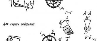
Drawing
Table 1
| Sharpening shape | |||
| Number | Front surface | Sketch | Application area |
| I | Flat, positive rake angle | Machining gray cast iron, bronze and other brittle materials | |
| II | Flat with negative bevel | Processing of malleable cast iron, steel and steel casting kgf/mm, as well as kgf/mm with insufficient rigidity of the technological system. Use a chipbreaker to remove and crush chips | |
| IIa | Flat, negative chamfer and brazed chipbreaker | Processing of steel and steel castings kgf/mm when curling and crushing chips is necessary | |
| III | Curvilinear, with negative chamfer | Processing steel kgf/mm when curling and crushing chips is necessary | |
| IlIa | Flat, with a small hole and | Processing of steel and steel castings at kgf/mm | |
| IlIb | Flat, with a small hole and | Processing of steel and steel castings at kgf/mm | |
| IV | Flat, negative rake angle | Roughing of steel and steel castings kgf/mm contaminated with non-metallic inclusions. Dealing with shocks in a harsh process system | |
| V | Curvilinear, with negative chamfer | Processing of stainless steels kgf/mm | |
| VI | Processing of materials from kgf/mm | ||
| VIa | Curvilinear, with negative chamfer | Processing of materials up to 130 kgf/mm | |
| VIb | Processing of materials up to 120 kgf/mm | ||
| VII | Flat with negative rake angle | Processing of materials with over 120 kgf/mm | |
2. Finish the front and rear surfaces along the main cutting edge and along the radius. 1, 2. (Changed edition, Amendment No. 1, 2).
3. To strengthen the tip of the cutter and better heat dissipation, it is recommended to sharpen the auxiliary plane at an angle of 15° over a length of 3 ... 5 mm.
table 2
mm
| Incisors | Head width | |||||||
| Elements of the cutting part of the incisors | until 3 | 10-12 | 15-20 | St. 20 | ||||
| Turning, planing, slotting | Cut-off, slotted | Dullness | ||||||
| Chamfer width | 0,15 | |||||||
Table 3
mm
| Incisors | Elements of the cutting part of the incisors | Section | |||||||||||||
| — | — | 16x12 | 20x16 | 25x20 | 32x25 | 40x32 | 50x40 | ||||||||
| 6x6 | 8x8 | 10x10 | 12x12 | 16×16 | 20x20 | 25x25 | 32x32 | 40x40 | 63x40 | ||||||
| — | — | 16x10 | 20×12 | 25x16 | 32x20 | 40x25 | 50x32 | 63x50 | |||||||
| 6* | 8* | 10* | 12* | 15 | 20 | ||||||||||
| Planing | Pass-through, undercut | ||||||||||||||
| Pass-through, undercut | Vertex radius | ||||||||||||||
| Boring | |||||||||||||||
| Pass-through, undercut | Chamfer width | 0,15-0,2 | 0,3-0,4 | 0,6-0,8 | 0,9-1,2 | ||||||||||
| Turning | Boring | 0,1-0,15 | 0,2-0,3 | 0,4-0,5 | |||||||||||
| Passing, scoring, boring | Point shape III | ||||||||||||||
| Sharpening shape IIIa, IIIb | 8-10 | 10-12 | 14-10** | 16-18 | 22-24 | 28-30 | |||||||||
| Passing | Sharpening form IIa | ||||||||||||||
________________
* Diameters of the drawn part of the boring cutters. ** The text corresponds to the original. — Note.
4. The geometric parameters of the cutting parts of the incisors when sharpening and finishing them with diamond wheels are indicated in Figure 2.
Selecting a beveled cutter
The choice of the necessary tool depends on the following requirements that are presented in the manufacture of a particular part. These requirements include:
- type of processing (finishing, semi-roughing, roughing, high-precision processing);
- tool feed directions (right or left);
- the nature of cutting or removing a layer (passing, thrust, scoring, threading);
- holder length;
- type of tip (solid, welded, removable);
- shape of the cutting element (triangular, rectangular, special design).
Depending on the complexity of the problem being solved, a bent cutter is selected that is capable of high-quality processing on a specific type of machine. The most universal is considered to be a bent through cutter with replaceable plates. The exact purpose of a particular instrument is determined by the accepted standard and indicated on the marking. The bent cutter T15k6 is used for surface treatment of parts made from various grades of steel, including alloyed ones. Alloy VK8 is used for roughing work, drilling, processing of internal surfaces, and milling. The variety of types of structures requires their evaluation according to the criterion of efficiency - cost. It is this that affects the final price of the manufactured part.
Cutting modes
A turning type through cutter can be used in a fairly simple operating mode. They can make longitudinal as well as transverse movements, depending on the profile of the part and its processing.
It is worthwhile from the very beginning to carry out the rough processing process with only one device, which will be intended specifically for this purpose, and then create a cleaner pass over an almost finished type of surface. If during the roughing process the total thickness of up to several millimeters will be removed over time, then during finishing this figure goes up to tenths in several passes.
Cutting modes
The process of operating through cutters is quite simple. Depending on the shape of the workpiece and the processing method, the direction of movement is chosen: longitudinal or transverse.
Please note the purpose of the tool: tools for roughing are prohibited from being used for finishing work and vice versa. It is also prohibited to change the established order of work:
It is also prohibited to change the established order of work:
- First of all, rough work is performed, which is characterized by a deep degree of impact: during processing, it is possible to remove up to 5 millimeters of metal in several passes.
- Finishing work is carried out in order to comply with the exact parameters of the product. The thickness of the cut metal should not exceed tenths of a millimeter.
Passing cutters are an indispensable tool for processing the metal surface of rotating elements. The types of work depend on the shape and structure of the devices. Have you observed the process of external processing of parts? Some turners believe that domestic cutter manufacturers are not inferior to famous foreign companies, including the German manufacturer Optimum. What do you think about this? Express your opinion in the comments section.
What is a lathe scoring tool used for?
There are 8 types of cutters in total: pass-through, boring, cutting-off, slotting, chamfering, shaping and scoring. Each of them is used in specific operations. For example, parting cutters are designed to separate finished products from workpieces, and boring cutters are designed to bore holes or create internal chamfers. But the scoring cutter has a wider application. Almost every basic operation on a lathe is performed using this tool. With its help, you can cut ledges at right or acute angles, create external chamfers, grind the end and any other external surface of a cylindrical part. Thus, it is one of the most important tools, as it directly influences the initial formation of the finished product.
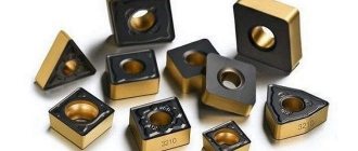
Prefabricated cutters for lathes
Considering the main types of turning tools, one cannot fail to mention tools with a prefabricated structure, which are considered universal, since they can be equipped with cutting inserts for various purposes. For example, by attaching cutting inserts of various types to one holder, you can obtain cutters for processing metal workpieces at different angles on a lathe.
Prefabricated cutters
As a rule, such cutters are used on CNC machines or on special machines and are used for contour turning, boring blind and through holes and other specialized work.
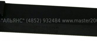
Markings used
The quality of purchased scoring cutters must meet the requirements specified in GOST 18871-73, 18880-73, 28980-91, 29132-91 and the technical specifications of manufacturing companies, if they are manufactured according to such a document. These standards indicate the design features of products, differences in geometry and dimensions. The marking of scoring cutters depends on their type. The table shows the marking features
| Type of turning scoring tools | Components of the designation | An example of a symbol and its explanation |
| End with high-speed steel plates | Type in the direction of supply, taking into account the cross-section, length and GOST | Cutter 2112-0038 GOST 18871-73, where: 2112-0038 – left cutter with a holder section of 32x20 mm and a length of 170 mm, produced in accordance with GOST 18871-73 |
| Bent with carbide inserts | Type in feed direction, cross-section, plate material and GOST | Cutter 2112-0007 VK6 GOST 18880-73, where: 2112-0007 – right cutter with a holder section of 25x16 mm with a plate made of VK5 material, produced in accordance with GOST 18880-73 |
| With replaceable cutting inserts made from ultra-hard materials | Type in the direction of supply, taking into account the cross-section, length and GOST | Cutter 2110-2395 GOST 28980-91, where: 2110-2395 – right cutter with a cross-section of 32x32, with a cutting part length of no more than 25 mm, with a cutting plate SNUN-050304, produced in accordance with GOST 28890-91 |
| Feedthroughs with replaceable polyhedral plates | Symbol according to GOST 26476-85 |
Wood cutters for a lathe: purpose and design of elements
The main purpose of wood turning tools is manual processing of a part rotating in a special machine. The lathe used for these purposes is designed to impart rotation to the body. Wooden blanks, which are initially round in shape, are mounted on a lathe using two clamps. One clamp is connected to an electric motor, which sets the part in motion.
The choice of the type of turning cutter, its sharpening and condition largely determines the possibility of certain operations and the manufacture of parts of the required configuration
Important! On the motor side, the fixation must be rigid so that rotational movements do not occur at idle. The cutters, which are fixed to the rotating mechanism, perform processing of the rotating body. Depending on the strength, shape and sharpness of the cutter, marks are formed on the wooden workpiece
This also determines the shape of the workpiece
Depending on the strength, shape and sharpness of the cutter, marks are formed on the wooden workpiece. This also determines the shape of the workpiece
The cutters, which are fixed to the rotating mechanism, perform processing of the rotating body. Depending on the strength, shape and sharpness of the cutter, marks are formed on the wooden workpiece. This also determines the shape of the workpiece.
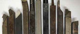
The design of a lathe cutter consists of a working metal part and a wooden handle. The working element conventionally consists of a blade, body and shank. The blade consists of a front, back and pointed angle. The size of the sharpening angle depends on the material of the workpiece. Most often, craftsmen use sharp corners when working with wood. The body is the main part for which the turner holds the cutter on the armrest of the machine with his non-working hand. The shank is a narrowed part into which the body of the tool goes. It is on this that the handle of the turning tool is attached.
The handle structure consists of a base and a neck. The base is the larger part of the handle that the turner holds with his hand. The neck is represented by a small cylindrical part with a metal fastening ring. It is designed to prevent the handle from cracking while being pressed onto the shank of the working part.
Wood turning tools consist of a back corner, a pointed corner and a rake corner.