Welding is one of the most commonly used methods of joining metals and alloys. Even masters sometimes make seam defects, not to mention beginners. When carrying out such work at home, visual inspection is sufficient. In production, various methods are used to control the quality of the weld, and one of the most advanced is radiographic testing.
Brief description of the method
Metal parts are connected using different types of welding, which can result in weld defects.
It's connected with:
- violation of work technology;
- foreign bodies entering the welding site;
- insufficient welder qualifications, etc.
All this leads to a deterioration in the quality of the seam and a decrease in its strength.
X-ray inspection (RT) of welded joints is a non-destructive method that allows you to identify hidden defects at an early stage and avoid accidents in the future.
This is a highly accurate method with which you can objectively assess both the nature and size of defects. The technique allows you to monitor the condition of welds on pipelines, tanks, various equipment and metal structures, etc.
Decoding
Interpretation of radiographs is carried out in a shaded room using a negatoscope. It is a device whose purpose is to view radiographic images, including radiographs, through transmission. The negatoscope provides the ability to adjust the brightness of the lighting. If its value is too high, small defects may be missed.
After decoding, a conclusion is drawn up. Before resorting to this method, it is necessary to find out what weld defects are detected using radiographic testing. These include:
- undercuts;
- lack of penetration;
- cracks;
- pores;
- foreign inclusions;
- slags
In addition, it is possible to evaluate the amount of concavity and convexity in places where visual inspection is not possible. Abbreviations are used when writing results. So, “T” means a crack, “N” is a lack of penetration, “P” is a pore, “W” is slag, “V” is the inclusion of tungsten, Pdr is an undercut. The size of the defect is indicated next to the letters. The nature of the distribution is also taken into account.
On this basis, shortcomings are divided into groups:
- Separate.
- Chains . There are more than three defects on one line.
- Clusters . Location of at least three defects in one place.
The size of the defect is indicated in millimeters.
GOST and other requirements
The radiographic method of testing welded joints is regulated by GOST 7512-82. This method allows you to control the weld with a thickness of the welded elements from 1 to 400 mm, and when using powerful equipment - up to 500 mm.
For this purpose, X-ray, bremsstrahlung and gamma radiation are used, and radiographic film is used to obtain an image.
The basic requirements for accessories for such control are as follows:
- Markings comply with GOST 15843-79.
- Radiographic films meet technical specifications.
- The radiation source complies with GOST 20426-82.
- Intensifying screens can be metallic or fluorescent.
- Lightproof cassettes ensure that the screen is pressed tightly against the film.
- The lead screen protects the film from scattered radiation.
- Sensitivity standards can be plate, wire or groove.
Cost of the service provided
When using radiography, understanding pricing in this field is important. The specific cost of control functions using radiation depends on many factors related to the proper distribution of working time, the use of instruments and special means.
As a rule, performing such work on your own is impractical due to the high cost of initial costs for purchasing equipment and materials, training personnel, and obtaining the required permits.
For these reasons, most often processes related to radiographic testing are entrusted to specialized organizations that have at their disposal:
- Certified equipment and materials;
- Experience in organizing work with a minimum level of production and time costs;
- Supporting documents and information about the level of technical equipment and competencies;
- Sufficient number of qualified and experienced personnel.
Price list for work on non-destructive testing of welded joints using the radiographic method
The final price of radiographic inspection of welded joints depends on the number of elements requiring inspection, time frames and other factors that may complicate the inspection.
Properties and capabilities of X-ray
The peculiarity of radiography is that the permeability of materials depends on the length of the generated rays. In dense materials they are scattered and partially absorbed. The lower the density of the connection being tested, the clearer the image will be.
The ability of some chemical elements to glow for several seconds under the influence of X-ray radiation makes it possible to expose a special film and obtain an image of existing seam defects.
If the material being tested is homogeneous, the result will be a light and monochromatic image. If there are various defects, cavities, voids, it will have darkening.
Some models of flaw detectors use the ability of ionized air to transmit electricity. The higher the degree of ionization, the better the current is conducted. This principle makes it possible to obtain an image not on film, but on the screen of an oscilloscope when performing RC.
In large quantities, X-ray radiation negatively affects the human body, irradiating cells and tissues. Large doses lead to the development of radiation sickness and even death. Therefore, the use of fluoroscopy to control the quality of welds requires strict adherence to safety rules.
Requirements for devices
X-ray inspection of welds depends on several factors:
- intensity of the transmitted flow, so that taking into account dispersion a clear image is obtained;
- the generator must operate with the same power throughout the study, only under this condition the readings will be reliable;
- a high sensitivity of the element that captures the light signal is required, otherwise the picture will be blurry;
- the ability of the device to detect defects is determined by the minimum dimensions of the recognized object; the strength of the welded joint directly depends on the size of voids or inclusions.
Scope of flaw detection
The X-ray method of checking welded joints makes it possible to accurately determine such parameters of existing defects as size, shape and location in space.
It allows you to control the quality of welds at critical facilities, such as main oil, gas, water pipelines, during the construction of structures and equipment for nuclear power plants, in machine, aircraft, shipbuilding, etc.
History of the creation and implementation of the methodology
Initially, the quality of welds on metal structures used in aviation was assessed using radiation flaw detection. Over time, scientists and practitioners accumulated enough knowledge to publish the first manual in 1934, which described in detail the technology of scanning electric arc welding areas with X-rays. In the middle of the 20th century. Thanks to a significant expansion of the development and research bases, the production of X-ray units was put on stream.
By the beginning of the 1960s. To control the quality of welded joints using this technology, standard installations were produced. These were mainly RUP devices, which were developed by . The advantages of these devices:
- X-ray energy range from 50 to 400 kV,
- precise focusing of X-ray tubes,
- radiation severity,
- power.
The development and improvement of technology was influenced by the Soviet scientist A.K. Trapeznikov, as well as his followers - B.V. Borshchev, S.T. Nazarov, O.T. Silchenko, S.V. Chernobrovov.
additional information
Before using the radiographic quality control method, you need to know that its diagnostic range is limited by the sensitivity of the device.
Using a flaw detector it is impossible to detect:
- voids that are 50% smaller than the standard values for the specified device and are located in a direction parallel to the action of the x-ray beam;
- inclusions located in the direction of the beam, the size of which is 2 times less than the sensitivity of the device;
- defects that coincide in the photograph with the edges and sharp corners of the elements being tested.
We recommend reading How ultrasonic flaw detection is used
This method detects all other defects quickly, efficiently and with high accuracy.
When are radiographic techniques not used?
The radiographic inspection method of welds is not used in several cases:
- If the connection has cracks and lack of fusion with an opening value below standard values. In this case, there is also a discrepancy between the opening plane and the direction of transmission.
- For inclusions and discontinuities having a size in the direction of transmission of less than twice the control sensitivity.
- In case of inclusions and discontinuities, when their projection in the photograph absolutely does not correspond to the image of the constructed parts.
- With sudden changes in metal cracks.
The most accurate way to control metal structures and welded joints is flaw detection with x-ray scanning. It helps to determine the nature, types, location of defects.
Equipment design features
Nowadays, radiographic testing, related to digital flaw detection, is more often used. The resulting radiation image is converted into a digital image and the information is displayed on the screen.
The detector for monitoring x-rays or gamma radiation that passes through the object being tested is a photodiode with a scintillator, which is susceptible to radiation and emits a visible spectrum of light that is in direct proportion to quantum energy.
Such radiation produces a current inside the photodiode, the radiation is converted into electricity and then displayed on the screen.
The detector units are moved relative to the object being tested and receive a continuous stream of information, which is recorded in the computer memory for further detailed testing. To quickly assess the quality of the connection, the resulting image is immediately displayed on the screen.
Gamma ray flaw detectors
They provide a given frequency of gamma radiation intensity fluctuations. As a result of changes in radiation intensity, transverse stripes are created in the image.
The existing radiation intensity deviations are higher than the statistical noise values. Modern technology, equipped with advanced software, makes it possible to reduce these fluctuations. Such X-ray machines are conditionally applicable for performing RK welds.
X-ray device
These devices have a constant potential and high-frequency fluctuations, random in time. They provide a deviation in gamma radiation intensity of more than 1%. In this regard, the use of these devices when performing radiometric monitoring is not recommended.
For X-ray inspection it is necessary to use equipment that has the following indicators:
- radiation stability – more than 0.5%;
- fluctuation frequency – not higher than 0.1 Hz.
Equipment and tools for performing x-ray inspection of welds
To carry out this control method, a radiating element in a special container is used. Such devices are produced in pulse mode and with a constant voltage at the anode.
Pulse X-ray machines
Pulse devices are more modern. They are light in weight and easy to adjust, but the quality of the photographs is slightly lower than on devices with a constant voltage at the anode. It is possible to shoot not only in the forward direction, but in panoramic mode.
X-ray machines with constant potential
The choice of this type of device is presented on the market wider than pulse devices. The device has a constant voltage across the X-ray tube. Images from it are obtained with higher quality and high resolution, since it is possible to regulate the voltage for a given thickness. They are produced either in direct shooting direction or with panoramic direction, depending on the purpose.
Operating principle of radiographic testing installations
The main part of the device used for radiographic monitoring of the condition of the seam is the emitter. It serves to create rays and emit them.
The emitter is made in the form of a vacuum vessel, which contains the anode, cathode and filament. During the acceleration that charged particles develop, X-rays are generated that illuminate the product under study.
The electrical potential created between the cathode and anode accelerates the electrons released by the cathode. These initial rays are still not enough for the device to operate.
When colliding with the anode, the rays are slowed down, which leads to their stronger generation. Their collision with the anode leads to the formation of electrons on it. As a result, rays are formed and sufficient radiation is generated.
The emerging rays move in the direction of the quality control location. Where the metal is dense, they are almost completely absorbed, and in places of defects they pass further.
The transmitted rays on the film form an image, the contrast of which depends on the number of rays passing through the seam. The more defects there are, the clearer this place appears in the picture. This way their location and size are determined.
What are the requirements?
When performing radiographic testing, any existing X-ray equipment can be used. Manufacturers rarely indicate in the characteristics data on fluctuations in the radiation intensity of the device, because this value is not critical.
Since radiometry ensures the collection of information online, the following requirements are imposed on the X-ray machines used:
- The density of the gamma flux passing through the object under study must be sufficient to provide enough time to record the thickness of the part along the scanned area.
- The gamma radiation intensity must be constant.
To ensure high-quality radiometric monitoring, a highly stable radiation source is used, guaranteeing maximum beam flux density and energy spectrum.
Safety at work
Although the equipment used for radiographic testing emits small doses of radiation, the following safety rules should not be neglected:
- The device must be shielded so as not to release rays beyond the area in which the control is carried out. Screens must be installed in the walls of the room in which such research is carried out so that radiation does not spread to people working in neighboring workshops.
- You should spend a minimum of time near a working device. If checking the quality of a seam is carried out on the street, then it is better to move away from it. If the device is located indoors, then during its operation you need to be near it for a minimum of time.
- The operator of radiographic equipment must wear personal protective equipment. There should be no strangers nearby while the equipment is operating.
- Before using the device, you need to check its functionality and the correctness of the settings. Most often, emergency situations occur due to incorrect settings or equipment malfunction.
- It is necessary to control that the resulting radiation has time to be eliminated from the body. The radiation dose can be determined using a dosimeter. The small doses of radiation received have a cumulative effect.
- It is especially important to control the level of air ionization in a closed laboratory. Radiation causes the air to ionize, resulting in the creation of electricity.
We recommend reading: How to make a potbelly stove for your garage yourself
Identification of defects
The presence of the following defects in the weld seam is unacceptable:
- Cracks (cold and hot). Before the seam hardens, hot cracks may appear, and after it has completely hardened, cold cracks may appear. They are often invisible during external inspection of the seam.
- Por. This defect is the most common during welding work. In most cases, its appearance is associated with improperly or insufficiently prepared surfaces to be joined, the presence of drafts, etc.
- Slags and other foreign bodies.
- Burn-through. It occurs when the welder is insufficiently qualified or the equipment parameters are incorrectly selected. It appears in the form of through holes in the seam.
- Undercut. A defect in the form of a groove located in the part being welded along the weld seam.
- Influx. During operation, filler material flows onto the base metal, but does not form reliable fusion with it.
- Lack of cooking. An incorrectly selected mode of work, i.e. low current, does not allow the parts to be connected to be fully and efficiently welded.
- Loose areas. They are characterized by a fragile seam structure.
Requirements for images and features of their decoding:
- Only well-dried photographs are decrypted. They should be free from scratches, fingerprints, etc.
- Decoding is performed in a darkened room using negatoscopes.
- The results obtained are recorded in a special journal, and the conclusion is sent to the technical control department.
Defects in argon TIG welding
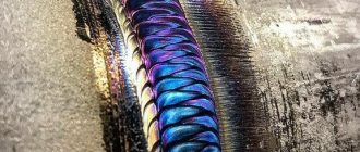
The following discontinuities are unique to the argon TIG welding process. These breaks occur in most metals welded in the process, including aluminum and stainless steel. The argon welding method produces a clean, uniform weld that is easily interpretable under radiography.
Tungsten inclusions
Tungsten inclusions
Tungsten is a brittle and inherently dense material used in the electrode of tungsten inert gas welding. If incorrect welding procedures are used, tungsten can get into the weld.
In an x-ray of a weld, tungsten is denser than aluminum or steel, so it appears as a lighter area with a clear outline on the x-ray.
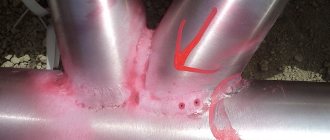
Oxide inclusions
Oxide inclusions
usually visible on the surface of the material being welded (especially aluminum). Oxide inclusions are less dense than the surrounding material and therefore appear as dark, irregularly shaped inhomogeneities on an x-ray diffraction pattern.
.
Advantages and disadvantages of the method
This method of quality control of welding seams is highly effective, because has the following advantages:
- To get an idea of the condition of a seam made by any welding method, just a few seconds are enough.
- RK has higher accuracy compared to other non-destructive testing methods.
- RK detects a wide range of defects.
- Radiography shows not only the location of the defect, but also its size and type.
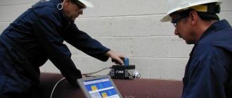
- The method can be used in the field, which is convenient when monitoring pipelines or inspecting construction sites.
The radiographic testing method also has its disadvantages:
- X-rays require special equipment and are expensive.
- It is necessary to use disposable consumables: film or plates, as well as reagents, screens, etc.
- To perform work, the operator must undergo training and pass exams.
- To get a reliable result, you need to configure the equipment correctly.
- The radiation from the device is hazardous to health.
Safety
For all its advantages, the method is potentially hazardous to health. Therefore, it is necessary to shield the device. The controller should not be unnecessarily in the irradiation area. Access there to unauthorized persons should be prohibited. To do this, warning signs should be posted.
When working indoors, its walls must be covered with shielding plates. The controller must be provided with a set of protective clothing. Before starting the process, it is necessary to check the serviceability of the equipment.
X-ray inspection technology
Before applying this technology, be sure to clean the surface. The quality of the settings greatly affects the accuracy of the results obtained.
Radiographic testing sequence:
- Installation of the device. On one side of the area being tested there should be an emitter, and on the other, a flaw detector sensor.
- Turning on the device. At this time, a beam of rays passes through the seam and enters the sensor. The equipment can operate from a battery or from the mains.
- Transmission of the received signal by the sensor to film or screen. This depends on the model of the device used.
- Recording a digital analog signal to a storage device.
- Deciphering the information received and recording existing defects in the relevant documentation.
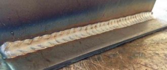
For welds
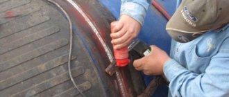
For classic seams, the procedure for monitoring their quality using X-ray control includes the following steps:
- removal of slag, scale, and any contaminants from the weld being examined;
- marking and marking of the joint (a marking and a sensitivity standard are installed on each);
- choice of work plan;
- setting control parameters;
- direct transillumination;
- film processing;
- decoding the results;
- recording the received information in documentation.
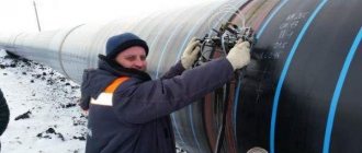
For pipelines
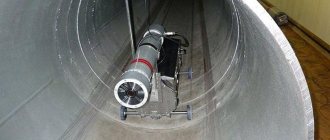
This method is actively used to control the seams of pipes of different diameters. It is often necessary to conduct research far from populated areas where it is impossible to deliver the installation.
In this case, compact devices – crawlers – are used. They move independently inside the pipe and are controlled remotely. The devices are designed to work in pipes with a diameter greater than 325 mm.
It does not matter where the object being studied is located - above, underground or under water. Climatic conditions do not matter, so it can be used in any region and at any time of the year.
On command, the device stops and takes radiographs or panoramic photographs.
We recommend reading: How to weld heating pipes using electric welding
For tanks
During acceptance of tanks, visual inspection of welded joints is first carried out and only then radiographic inspection. At the intersection of seams, films must be placed in an X- or T-shaped direction.
The length of the image must be at least 240 mm, and the width must correspond to the standard one. Check the butt seams on the walls of the tank, the bottom, as well as at the places where they meet.
If unacceptable defects are detected in this area, an additional photograph is taken. To check seams on tanks, flaw detectors of at least level 4 are used, and the results are interpreted by specialists of at least level II.
For different types of connections
Radiographic testing of different types of welds is carried out in accordance with GOST 7512, OST 26-11-03, OST 26-11-10. Before carrying out work, take into account the characteristics of the metal and the weld being tested. Fillet welds are checked according to GOST 26-2079.
Using this method, the quality of corner, T and butt joints, intersections of seams, etc. is controlled.
By type of metal
Using X-ray scanning, you can check the quality of welds and the main product made of different metals. The hardware settings will be different, because... The transmission of rays through different materials differs.
The quality of control depends on the correct settings.
Modern equipment allows not only to identify the type, size and location of defects, but also to decipher the results obtained automatically.
Important points
In any case, the final results of the measurements are influenced by several main factors.
- Stability of the supplied voltage characteristics.
- Precise geometric control parameters.
- Adjusting the size of the focal spot.
- Focal distance between the object being flaw-detected and the radiation converter.
According to the requirements of GOST 7512-86, which extends to RK control methods, a technological map must be developed for each inspected product. This is important because X-ray testing only demonstrates its effectiveness if all standards are fully observed.
Using filmless devices
Now, increasingly, instead of detectors that use film, devices are used where the radiation is immediately processed into digital form and displayed on a screen.
“Filmless” radiography is divided into the following types:
- Digital. X-rays are converted into electric current, the magnitude of which depends on the strength of the radiation. First, the rays hit the scintillator layer, where they turn into light photons. They penetrate the photovoltaic matrix located at the rear and activate a charge in it, which is read and appears as an image on the screen.
- Computer. The mechanism of photostimulated luminescence is used here. Some of the crystals store the absorbed energy, and after optical or thermal stimulation, the stored energy begins to glow. Barium fluorobromide is most often used as a phosphor. The more energy that hits the storage platter, the more visible light there will be in the image. To obtain a new image, the remaining glow on the screen is erased using a powerful beam of light, and the equipment can be used again.
Advantages of “filmless” radiography:
- the need to carry out “wet” processing of the resulting images;
- shorter exposure time;
- the ability to study parts with different radiation thicknesses.