To perform many types of work on wood, metal or other types of materials, it is not high speeds that are required, but good traction. It would be more correct to say - moment. It is thanks to him that the planned work can be completed efficiently and with minimal power losses. For this purpose, DC (or commutator) motors are used as a drive device, in which the supply voltage is rectified by the unit itself. Then, to achieve the required performance characteristics, it is necessary to adjust the speed of the commutator motor without loss of power.
Features of speed control
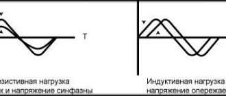
It is important to know that each motor, when rotating, consumes not only active, but also reactive power. In this case, the level of reactive power will be higher, which is due to the nature of the load. In this case, the task of designing devices for regulating the rotation speed of commutator motors is to reduce the difference between active and reactive powers. Therefore, such converters will be quite complex, and it is not easy to make them yourself.
You can construct only some semblance of a regulator with your own hands, but there is no point in talking about saving power. What is power? In electrical terms, it is the current drawn multiplied by the voltage. The result will give a certain value that includes active and reactive components. To isolate only the active one, that is, to reduce losses to zero, it is necessary to change the nature of the load to active. Only semiconductor resistors have these characteristics.
Therefore, it is necessary to replace the inductance with a resistor , but this is impossible, because the motor will turn into something else and obviously will not set anything in motion. The goal of lossless regulation is to maintain torque, not power: it will still change. Only a converter can cope with such a task, which will control the speed by changing the duration of the opening pulse of thyristors or power transistors.
Main goals
The speed controller in any electrical installation is designed to adjust the number of revolutions for a certain unit of time. Typically, rotation speed is measured in revolutions per minute (RPM). When the start button is pressed, a start pulse is generated; at this moment, the speed controller adjusts the engine for a soft start, adjusting the frequency, strength and voltage of the current. Certain technical procedures involve reducing the rate of movement of the working parts of the equipment by a specific amount.
Depending on the operating conditions, the speed controller connected to the electric motor can perform a number of other tasks:
- control of the current temperature state and pressure level in the system without the need to use a feedback unit with driven equipment parts or in the case of using an asynchronous motor;
- increasing the degree of conservation of electrical energy without loss of power. By adapting the engine for a smooth start, the controller reduces efficiency losses when starting and stopping the rotor, in the process of increasing or decreasing speed and adjusting thrust. If a motor is selected to operate in short bursts (for example, an air compressor), which is also quite small, a speed controller is a necessity;
- Induction motors under high shaft load use a regulator to prevent the starting impulse from being too strong. This reduces the likelihood of false triggering of protective automation by reducing the load on current-carrying networks;
- an electric motor for operation in a three-phase network requires a regulator to stabilize the speed at a certain value. This facilitates the implementation of precise technological operations, the fineness of which directly determines the quality of the final product. Violation of the technique may occur due to surges in power supply or load on the shaft. With a preinstalled regulator, the 220 volt electric motor operates more stably;
- if the system has a standard configuration and the electric motor is powered from a 220V network, the speed controller often performs only basic functions - changing the speed from zero to the permissible limit. This also includes maintaining torque when the engine is running slowly.
The availability of certain capabilities in a particular regulator model depends on its design. The principle of operation and design features also play an important role.
Generalized controller circuit
An example of a controller that implements the principle of controlling a motor without power loss is a thyristor converter. These are proportional-integral circuits with feedback, which provide strict control of characteristics, ranging from acceleration-braking to reverse. The most effective is pulse-phase control: the repetition rate of the unlocking pulses is synchronized with the network frequency. This allows you to maintain torque without increasing losses in the reactive component. The generalized diagram can be represented in several blocks:
- power controlled rectifier;
- rectifier control unit or pulse-phase control circuit;
- tachogenerator feedback;
- current control unit in the motor windings.
Before delving into a more precise device and principle of regulation, it is necessary to decide on the type of commutator motor. The control scheme for its performance characteristics will depend on this.
Frequency converter payback
Electricity is constantly becoming more expensive, and managers of organizations are forced to save in different ways. In industrial production, most of the energy is consumed by mechanisms with electric motors.
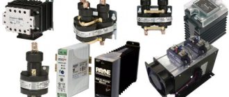
Manufacturers of devices for electrical machines and units offer special devices and instruments for controlling electric motors. Such devices save electrical energy. They are called inverters or frequency converters.
The financial costs of purchasing a frequency generator do not always justify the cost savings, since their cost is comparable to the cost of saved energy. It is not always possible to quickly equip a mechanism with an inverter. What difficulties arise in this? Let's look at ways to start asynchronous motors to understand the advantages of inverters.
Types of commutator motors
At least two types of commutator motors are known. The first includes devices with an armature and an excitation winding on the stator. The second includes devices with an armature and permanent magnets. It is also necessary to decide for what purposes the regulator needs to be designed:
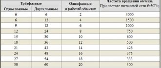
- If it is necessary to regulate with a simple movement (for example, by rotating a grinding stone or drilling), then the speed will need to be changed within the range from some minimum value, not equal to zero, to the maximum. Approximate value: from 1000 to 3000 rpm. A simplified circuit with 1 thyristor or a pair of transistors is suitable for this.
- If it is necessary to control the speed from 0 to maximum, then you will have to use full-fledged converter circuits with feedback and strict control characteristics. Usually, self-taught craftsmen or amateurs end up with commutator motors with an excitation winding and a tachogenerator. Such a motor is a unit used in any modern washing machine and often fails. Therefore, let’s consider the principle of controlling this particular engine, studying its structure in more detail.
Connection methods
Before you begin integrating the speed controller, you must read the manual. The type and mechanism of operation of the existing model is indicated there. Without this information, you can make a mistake and cause a module or engine breakdown. As a rule, the connection diagram for the speed controller does not differ much between the varieties of the latter, so the user manual will present a drawing of a typical electrical circuit.
After studying the integration diagram, you need to understand how the pinout method is used. With its help, the number of pins for full control of the existing type of electric motor is determined. Next, a comparison is made between the output contacts of the electric motor and the color codes of the regulator connectors. It is necessary to select devices so that there are no unconnected outputs. If any contact remains unused, they can be short-circuited so that the operation of the motor is not disrupted. When all the symbols match, you can start connecting and connecting to the power supply.
Motor design
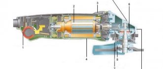
Structurally, the engine from the Indesit washing machine is simple, but when designing a controller to control its speed, it is necessary to take into account the parameters. Motors may have different characteristics, which is why the control will also change. The operating mode is also taken into account, which will determine the design of the converter. Structurally, the commutator motor consists of the following components:
- An armature, it has a winding laid in the grooves of the core.
- Collector, a mechanical rectifier of alternating mains voltage, through which it is transmitted to the winding.
- Stator with field winding. It is necessary to create a constant magnetic field in which the armature will rotate.
When the current in the motor circuit, connected according to the standard circuit, increases, the field winding is connected in series with the armature. With this inclusion, we also increase the magnetic field acting on the armature, which allows us to achieve linearity of characteristics. If the field remains unchanged, then it will be more difficult to obtain good dynamics, not to mention large power losses. It is better to use such motors at low speeds, since they are more convenient to control at small discrete movements.
By organizing separate control of the excitation and armature, it is possible to achieve high positioning accuracy of the motor shaft, but the control circuit will then become significantly more complicated. Therefore, we will take a closer look at the controller, which allows you to change the rotation speed from 0 to the maximum value, but without positioning. This may be useful if a full-fledged drilling machine with the ability to cut threads will be made from the engine from a washing machine.
Making homemade relays
Making a homemade speed controller for a 12 V electric motor will not be difficult. For this work you will need the following:
- Wirewound resistors.
- Switch for several positions.
- Control unit and relay.
The use of wirewound resistors allows you to change the supply voltage and, accordingly, the engine speed. Such a regulator provides stepwise acceleration of the engine, has a simple design and can be made even by novice radio amateurs. Such simple homemade step regulators can be used with asynchronous and contact motors.
Operating principle of a homemade converter:
- Power from the network is sent to the capacitor.
- The used capacitor is fully charged.
- The load is transferred to the resistor and the bottom cable.
- The thyristor electrode connected to the positive terminal on the capacitor receives the load.
- A voltage charge is transmitted.
- The discovery of the second semiconductor occurs.
- The thyristor passes the load received from the capacitor.
- The capacitor is completely discharged, after which the half-cycle is repeated.
In the past, the most popular were mechanical regulators based on a variator or gear drive. However, they were not very reliable and often failed.
Homemade electronic regulators have proven themselves to be the best. They use the principle of changing step or smooth voltage, are durable, reliable, have compact dimensions and provide the ability to fine-tune the operation of the drive.
The additional use of triacs and similar devices in electronic regulator circuits allows for a smooth change in voltage power; accordingly, the electric motor will correctly gain speed, gradually reaching its maximum power.
To ensure high-quality regulation, variable resistors are included in the circuit, which change the amplitude of the incoming signal, providing a smooth or step change in the speed.
Scheme selection
Having found out all the conditions under which the motor will be used, you can begin to manufacture a speed controller for the commutator motor. You should start by choosing a suitable scheme that will provide you with all the necessary characteristics and capabilities. You should remember them:
- Speed regulation from 0 to maximum.
- Providing good torque at low speeds.
- Smooth speed control.
Looking at many schemes on the Internet, we can conclude that few people are creating such “units”. This is due to the complexity of the control principle, since it is necessary to organize the regulation of many parameters. Thyristor opening angle, control pulse duration, acceleration-deceleration time, torque rise rate. These functions are handled by a circuit on the controller that performs complex integral calculations and transformations. Let's consider one of the schemes, which is popular among self-taught craftsmen or those who simply want to put to good use an old motor from a washing machine.
All our criteria are met by a circuit for controlling the rotation speed of a brushed motor, assembled on a specialized TDA 1085 microcircuit. This is a completely ready-made driver for controlling motors that allow you to adjust the speed from 0 to the maximum value, ensuring torque maintenance through the use of a tachogenerator.
Frequency control
To solve this problem, frequency converters (drivers, inverters) are used, which are connected to the device. They provide rectification of the voltage coming from the source. The units inside generate voltage and frequencies at the required levels. Next, these parameters are supplied to the electric motor.
Stabilization of a 12V commutator motor All characteristics necessary for regulating operation are calculated by the frequency operator itself, focusing on internal algorithms that are installed by the manufacturer.
Among the advantages of this method it is worth highlighting:
- quickly achieve smooth adjustment of the speed of the electric motor;
- the ability to change the speeds and directions of rotation of the motors;
- the required parameters are independently supported;
- economic benefits.
Among the weaknesses, it is worth highlighting the mandatory presence of a converter, which must be purchased separately. But, in fairness, we note that the price of frequency devices is low and they can easily fit into the budget of any home, household, or enterprise.
Design Features
The microcircuit is equipped with everything necessary for high-quality engine control in various speed modes, from braking to acceleration and rotation at maximum speed. Therefore, its use greatly simplifies the design, while simultaneously making the entire drive universal , since you can select any speed with a constant torque on the shaft and use it not only as a drive for a conveyor belt or drilling machine, but also for moving a table.
The characteristics of the microcircuit can be found on the official website. We will indicate the main features that will be required to construct the converter. These include: an integrated frequency-to-voltage conversion circuit, an acceleration generator, a soft starter, a Tacho signal processing unit, a current limiting module, etc. As you can see, the circuit is equipped with a number of protections that will ensure stable operation of the regulator in different modes.
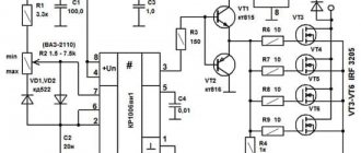
The figure below shows a typical circuit diagram for connecting a microcircuit.
The scheme is simple, so it is quite reproducible with your own hands. There are some features that include limit values and speed control method:
- The maximum current in the motor windings should not exceed 10 A (subject to the configuration shown in the diagram). If you use a triac with a large forward current, the power can be higher. Please note that you will need to change the resistance in the feedback circuit downward, as well as the inductance of the shunt.
- The maximum rotation speed is 3200 rpm. This characteristic depends on the type of engine. The circuit can control motors up to 16 thousand rpm.
- Acceleration time to maximum speed reaches 1 second.
- Normal acceleration is achieved in 10 seconds from 800 to 1300 rpm.
- The engine uses an 8-pole tachogenerator with a maximum output voltage of 30 V at 6000 rpm. That is, it should produce 8 mV per 1 rpm. At 15,000 rpm it should show 12 V.
- To control the motor, a 15A triac with a maximum voltage of 600 V is used.
If you need to organize a motor reverse, then for this you will have to supplement the circuit with a starter that will switch the direction of the excitation winding. You will also need a zero speed control circuit to give permission for reverse. Not shown in the picture.
Advantages and disadvantages
To summarize, we highlight the following advantages of CLEBO A3:
- Navigation based on camera and gyroscope.
- Building a room map.
- Build quality and performance.
- Extended delivery set.
- Several operating modes + polisher mode.
- Setting up a cleaning schedule.
- Control from smartphone and remote control.
- Working with voice assistants.
- Low noise level.
The downside of the iCLEBO A3 is the poorly implemented wet cleaning function, which is just wiping the floor with a dampened cloth without electronic control
It is also important to understand that the device is controlled via Bluetooth, that is, it will not be possible to start it remotely, for example, while at work. Well, the cost of a robot vacuum cleaner is 29,900 rubles, let’s be objective, it’s not affordable for everyone
Otherwise, there are no complaints about this model.
Finally, we recommend looking at the rating of the best robot vacuum cleaners with a camera:
Analogues:
- Xiaomi Mijia LDS Vacuum Cleaner
- GUTREND SENSE 410
- Roborock S6 Pure
- Ecovacs DeeBot OZMO 900
- HOBOT Legee-688
- iRobot Roomba 960
- Okami U90 Vision
Control principle
When the rotation speed of the motor shaft is set by a resistor in output circuit 5, a sequence of pulses is formed at the output to unlock the triac by a certain angle. The speed of rotation is monitored by a tachogenerator, which occurs in digital format. The driver converts the received pulses into an analog voltage, which is why the shaft speed is stabilized at a single value, regardless of the load. If the voltage from the tachogenerator changes, the internal regulator will increase the level of the output control signal of the triac, which will lead to an increase in speed.
The microcircuit can control two linear accelerations, allowing you to achieve the dynamics required from the engine. One of them is installed on the Ramp 6 output circuit . This regulator is used by washing machine manufacturers themselves, so it has all the advantages to be used for domestic purposes. This is ensured by the presence of the following blocks:
- Voltage stabilizer to ensure normal operation of the control circuit. It is implemented at pins 9, 10.
- Rotation speed control circuit. Implemented using MS pins 4, 11, 12. If necessary, the controller can be switched to an analog sensor, then pins 8 and 12 are combined.
- Starting impulse block. It is implemented at pins 1, 2, 13, 14, 15. It adjusts the duration of control pulses, delays, generates them from a constant voltage and calibrates.
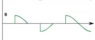
- Sawtooth voltage generation device. Pins 5, 6 and 7. It is used to control the speed according to the set value.
- Control amplifier circuit. Pin 16. Allows you to adjust the difference between the set and actual speed.
- Current limiting device at pin 3. When the voltage on it increases, the triggering angle of the triac decreases.
The use of such a circuit ensures full control of the commutator motor in any mode. Thanks to forced acceleration control, it is possible to achieve the required acceleration speed to a given rotation speed. Such a regulator can be used for all modern washing machine motors used for other purposes.
Changing the number of poles
Decreasing or increasing the number of pole pairs is another effective way to make adjustments. This option is especially relevant for multi-speed motor models with complex rotor windings. These elements are divided into specific groups and alternate during the work process. This is done through switching, connecting in a serial or parallel manner.
The advantages of this adjustment option include:
- high efficiency of the power unit;
- demanding mechanical output characteristics.
The cost of implementation is one of the highest when compared with other technologies. The weight and dimensions of the finished installation are also rather large, which requires free space for installation. The speed monitoring itself is carried out in steps of 1500 – 3000 rpm.
Conclusion
When voltage is applied to asynchronous motor models, the rotor jerks. This phenomenon negatively affects the operation of both the unit itself and its drive. That is why the adjustment is carried out according to the principle of a smooth start. It is provided by the following factors:
- start via LATR;
- acceleration and operation of the motor by switching windings according to triangle/star circuits;
- the use of protective devices, for example, a frequency converter.
It is important when regulating the speed not to lose power. Using the methods described above will allow you to determine rotations without reducing productivity. A wide selection of factory models, but you can also implement the part yourself.
Implementation of PWM
Many models of modern PLC controllers provide the ability to organize PWM. But sometimes the available channels are not enough and you have to use an interrupt handler.
PWM implementation algorithm:
- At the beginning of each pulse we set one and wait for the value to increase to the specified level.
- Reset the line to zero.
We advise you to study - Organization of operation of electrical distribution networks
The duration of the pulse is easier to track with a certain periodicity or steps. For example, ten adjustment steps correspond to 10% of the maximum value. First of all, it is necessary to determine the pulse frequency and the number of control stages. Next, the resulting values are multiplied. The result of the product will give the required frequency of timer interrupts.
If desired, you can select the appropriate timer frequency or the number of control stages and, through calculations, find the required pulse frequency.
Also on the topic of regulating the speed of a commutator motor, we offer the article “Control of a commutator DC motor using the PWM method”