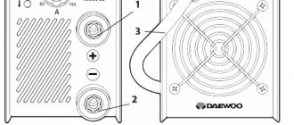
One of the main components of a truly high-quality seam is the correct and precise adjustment of the welding current in accordance with the task at hand. Experienced welders often have to work with metal of different thicknesses, and sometimes the standard min/max adjustment is not enough for proper work. In such cases, there is a need for multi-stage current regulation, accurate to the nearest ampere. This problem can be easily solved by connecting an additional device to the circuit - a current regulator.
The current can be adjusted in the secondary (secondary winding) and in the primary (primary winding). Moreover, each method of setting up a transformer for welding has its own characteristics that are important to consider. In this article we will tell you how to regulate the current in welding machines, provide diagrams of regulators for a semi-automatic welding machine, and help you choose the right welding current regulator for the primary winding for a welding transformer.
Methods for adjusting current
There are many ways to regulate the current, and above we wrote about the secondary and primary windings. In fact, this is a very rough classification, since the adjustment is still divided into several components. We will not be able to analyze all the components within the framework of this article, so we will focus on the most popular ones.
One of the most commonly used current control methods is to add a ballast at the output of the secondary winding. This is a reliable and durable method; you can easily make a ballast with your own hands and use it without additional equipment. Often, ballasts are used solely to reduce current.
In this article, we described in detail the operating principle and features of using a ballast for a semi-automatic welding machine. There you will find detailed instructions on how to make the device at home and how to use it in your work.
Despite many advantages, the method of adjusting the current through the secondary winding when used in conjunction with a welding transformer may not be very convenient, especially for novice welders. First of all, the ballast is quite bulky and its size can reach a meter in length. The device is also often underfoot and gets very hot, and this is a gross violation of safety regulations.
If you are not ready to put up with these shortcomings, then we recommend that you pay attention to the method when the welding current is adjusted through the primary winding. For these purposes, electronic devices that can be easily made with your own hands are often used. Such a device will easily regulate the current through the primary and will not cause inconvenience to the welder during operation.
The electronic regulator will become an indispensable assistant for a summer resident who is forced to weld under conditions of unstable voltage. Often houses are simply not allowed to use electrical appliances larger than 3-5 kW, and this is very limiting in their work. Using the regulator, you can configure your device so that it can operate smoothly even with low voltage. Also, such a device will be useful for craftsmen who need to constantly move from place to place while working. After all, the regulator does not need to be dragged around like a ballast, and it will never cause injury.
Now we will talk about how to make an electronic regulator from thyristors yourself.
Adjusting the welding machine
There are different ways to control the current of a welding machine.
With moving windings and core
The stiffness of the characteristic depends on the magnetic coupling between the primary and secondary coils. To change it, it is necessary to change the distance between the primary and secondary windings or the size of the air gap in the magnetic core. To do this, the core or coil is mounted on a special nut, and the screw is equipped with a handle. When it rotates, the nut is screwed on and the moving part changes its position, which leads to a change in current.
This method is used in alternating voltage devices, as well as those additionally equipped with diode bridges.
Core magnetization with constant voltage
Another control method is to magnetize the core with a constant voltage. The magnetized core increases the resistance to the magnetic flux created by the primary winding. This reduces the arc current.
Interesting! The operation of a magnetic amplifier is based on a similar principle. This device was used in electric drive control systems before the advent of thyristor converters.
Ballast resistances
One of the most common and simplest adjustment methods is to use ballast resistance:
- Active ballast. It consists of several wire or tape resistances that are switched if necessary to change the electric welding current. Can be used with all types of devices. In homemade low-power devices, instead of a set of resistances, a nichrome spiral or snake is used.
- Inductive ballast. This is a choke, the inductance of which can be changed, if necessary, by changing the number of turns or the size of the air gap in the magnetic circuit. Installed in series with the secondary winding before the diode bridge.
Thyristor control
This adjustment is used in rectifiers in which some or all of the diodes are replaced by thyristors. When the opening angle changes, the effective voltage value and current of the device changes. The angle is controlled by variable resistors or more complex circuits.
The disadvantage of this scheme is the transformation of constant voltage into pulsating voltage, which deteriorates the quality of the seam.
Important! When the opening angle is more than 90°, the amplitude value drops, which worsens the arc ignition process.
Adjusting the primary winding
The adjustment of the welding transformer currents through the primary is carried out by a thyristor switch - two thyristors connected back-to-back in parallel using a variable resistor connecting the control terminals or a small transistor circuit.
Adjustment of the primary thyristor switch allows you to control alternating voltage devices.
All these adjustment methods are losing their significance along with old devices and the spread of new, inverter ones. They are more economical, lighter, and some stores offer to exchange your old reel welder for a new one. But while the old devices are in operation, knowledge of how the welding current in the transformer is regulated will allow you to perform welding work more efficiently.
Thyristor regulator circuit
Above you can see a diagram of a simple regulator using 2 thyristors with a minimum of non-scarce parts. You can also make a regulator using a triac, but our practice has shown that a thyristor power regulator is more durable and operates more stably. The assembly diagram is very simple and according to it you can quickly assemble the regulator with minimal soldering skills.
The operating principle of this regulator is also simple. We have a primary winding circuit into which the regulator is connected. The regulator consists of transistors VS1 and VS2 (for each half-wave). The RC circuit determines the moment when the thyristors open, and at the same time the resistance R7 changes. As a result, we get the opportunity to change the current in the primary of the transformer, after which the current changes in the secondary.
Note! The regulator is adjusted under voltage, do not forget about this. To avoid fatal mistakes and avoid injury, it is necessary to isolate all radio elements.
In principle, you can use old-style transistors. This is a great way to save money, since these transistors can easily be found in an old radio or at a flea market. But keep in mind that such transistors must be used at an operating voltage of at least 400 V. If you find it necessary, you can use dinistors instead of the transistors and resistors shown in the diagram. We did not use dinistors, since in this version they do not work very stably. In general, this thyristor-based welding current regulator circuit has proven itself well, and on its basis many regulators have been manufactured that operate stably and perform their function well.
You could also see in stores the resistance welding regulator RKS-801 and the resistance welding regulator RKS-15-1. We do not recommend making them yourself, since it will take a lot of time and will not save you much money, but if you want, you can make RKS-801. Below you see a diagram of the regulator and a diagram of its connection to the welder. Open the pictures in a new window to see the text better.
Secondary welding current regulator - Metalworker's Handbook
Each control method can have a positive effect on the operation of the welding unit, but each method also has its own disadvantages, which it is advisable to know and be able to avoid unpleasant situations.
The welding process is a responsible procedure, therefore it determines almost any deviation from the norms. Using special regulators:
- The operating current is adjusted,
- The magnetic flux changes.
Therefore, the current regulator for a welding machine performs an important function and the main methods of regulation are: magnetic shunting, mobility of windings, as well as various types of chokes.
Methods for adjusting welding parameters
If you connect to the taps that are made on the second winding of the transformer, then there is the possibility of stepwise regulation of the electric current. When using this method, the number of turns changes, thus reducing or increasing the current.
But there are disadvantages to this method, which lie in the minimum adjustment ranges. And the control device will have to be of decent dimensions in order to withstand serious electrical overloads. You will also have to use powerful switches that can withstand high currents.
The secondary winding takes up significantly greater loads than the secondary winding, so this device wears out quickly. To improve the performance of this design, thyristors are used, which are integrated into the primary winding.
With the help of such a device, you can configure the welding machine, and it is very simple to do. To make a current regulator for a welding machine, you need to correctly select the resistances and other elements included in the circuit of this device.
Current regulator circuit for a welding unit
The thyristors in the device are installed in parallel so that they are turned on by the current generated by the two transistors. When the regulator is connected to the circuit, the thyristors are in the closed state, and the capacitors receive the charge due to variable resistance.
And when the capacitor reaches a certain voltage, the discharge current moves. After the transistor, the thyristor opens, connecting the load.
By changing the resistance of the resistor, it will be possible to adjust the connection of the thyristors. In this regard, the total current on the original transformer winding changes.
To achieve an increase or decrease in the adjustment range, the resistance of the resistor changes in the desired direction. If transistors are not available, the use of dinistors is an acceptable condition.
Regulator circuit with dinistors and transistors
A current regulator for a welding machine is mounted not only on transistors designed to produce an avalanche voltage, but also using dinistors.
This element must be connected with its anodes to the resistance terminals, and with its cathodes it must be connected to the other two resistors. Transistors of models P416, GT308 are used for regulators of welding devices, but there is also the possibility of connecting low-power transistors with similar characteristics.
Variable type resistors can be used SP-2, and MBM are used as permanent elements. In this case, it is necessary to select a resistance that will have a suitable operating voltage.
In order to properly assemble a control device for a welding machine, you need to use a textolite base with a thickness of 1.5 - 2 millimeters, then the installation process will be more convenient.
It is necessary to ensure that all parts involved in the circuit are insulated from the housing, since short circuits and an increase in temperature are possible. Serious overloads can lead to negative consequences and failure of both individual elements and the entire device.
If all the rules were followed when assembling the control device, and the parts were selected according to optimal parameters, then the regulator does not need to be adjusted.
But before using the device in full, you need to check the operation of the transistors included in the circuit, because they may not withstand the avalanche mode.
Thanks to the stable operation of the device, welding machines will be able to work normally with different materials and structures being welded.
Share a link to this material with your friends on social networks (click on the icons):
How to adjust the current when welding?
This is a fairly common question that has several solutions. There is one of the most popular ways to solve the problem; adjustment occurs through an active ballast connection at the output of the winding (secondary).
On the territory of the Russian Federation, welding for alternating current consists of a frequency of 50 Hz. A 220V network is used as a power source. And all transformers for welding have a primary and secondary winding.
Regulator for welding current
In units used in an industrial area, current regulation is carried out differently. For example, using the moving functions of the windings, as well as magnetic shunting, inductive shunting of various types. Ballast resistance stores (active) and a rheostat are also used.
This choice of welding current cannot be called a convenient method, due to the complex design, overheating and discomfort when switching.
A more convenient way to regulate the welding current is to wind the secondary (secondary winding) by making taps, which will allow you to change the voltage when switching the number of turns.
But in this case, it will not be possible to control the voltage over a wide range. They also note certain disadvantages when adjusting from the secondary circuit.
As a result, an optimal and convenient tool was found in which adjusting the welding current does not seem so confusing - this is a thyristor.
Experts always note its simplicity, ease of use and high reliability.
The strength of the welding current depends on turning off the primary winding for specific periods of time, at each half-cycle of the voltage. At the same time, the average voltage readings will decrease.
The principle of operation of a thyristor
The regulator parts are connected both in parallel and counter to each other. They are gradually opened by current pulses, which are formed by transistors vt2 and vt1. When the device starts, both thyristors are closed, C1 and C2 are capacitors, they will be charged through resistor r7.
At the moment when the voltage of any of the capacitors reaches the avalanche breakdown voltage of the transistor, it opens, and the discharge current of the joint capacitor flows through it. After the transistor opens, the corresponding thyristor opens and connects the load to the network.
Then the opposite half-cycle of the alternating voltage begins, which implies the closing of the thyristor, then a new cycle of recharging the capacitor follows, this time in the opposite polarity. Then the next transistor opens, but again connects the load to the network.
Welding with direct and alternating current
In the modern world, DC welding is used to a greater extent. This is due to the possibility of reducing the amount of filler material of the electrodes in the weld. But when welding with alternating voltage, you can achieve very high-quality welding results. Welding power sources operating with alternating voltage can be divided into several types:
- Instruments for argon arc welding. Special electrodes are used here that do not melt, making argon welding as comfortable as possible;
- Apparatus for the production of RDS by alternating electric current;
- Equipment for semi-automatic welding.
Alternating welding methods are divided into two types:
- use of non-consumable electrodes;
- piece electrodes.
There are two types of DC welding, reverse and direct polarity. In the second option, the welding current moves from negative to positive, and the heat is concentrated on the workpiece. And the reverse concentrates attention on the end of the electrode.
A DC welding generator consists of a motor and a current generator itself. They are used for manual welding during installation work and in the field.
Manufacturing of the regulator
To make a control device for welding current, you will need the following components:
- Resistors;
- Wire (nichrome);
- Coil;
- design or diagram of the device;
- Switch;
- Spring made of steel;
- Cable.
Operation of the ballast connection
The ballast resistance of the control apparatus is at the level of 0.001 Ohm. It is selected through experiment. Directly to obtain resistance, resistance wires of high power are mainly used; they are used in trolleybuses or on lifts.
Such resistance is turned on permanently or in another way, so that in the future it will be possible to easily adjust the indicators. One edge of this resistance is connected to the output of the transformer structure, the other is provided with a special clamping tool that can be thrown along the entire length of the spiral, which will allow you to select the desired voltage force.
Welding current measurement
Once you have made and configured the regulator, it can be used in operation. To do this, you need another device that will measure the welding current. Unfortunately, it will not be possible to use household ammeters, since they are not capable of working with semi-automatic devices with a power of more than 200 amperes. Therefore, we recommend using a clamp meter. This is a relatively inexpensive and accurate way to find out the current value; the clamp control is clear and simple.
Read also: What color are the wires in the socket?
The so-called “clamps” at the top of the device grip the wire and measure the current. There is a current measurement limit switch on the device body. Depending on the model and price, different manufacturers make clamp meters capable of operating in the range of 100 to 500 amps. Choose a device whose characteristics match your welding machine.
Clamp meters are an excellent choice if you need to quickly measure current without interfering with the circuit or connecting additional elements to it. But there is one drawback: clamps are absolutely useless when measuring DC current values. The fact is that direct current does not create an alternating electromagnetic field, so the device simply does not see it. But when working with alternating current, such a device meets all expectations.
There is another way to measure current, it is more radical. You can add an industrial ammeter to the circuit of your semi-automatic welding machine, capable of measuring large current values. You can also simply temporarily add an ammeter to the open circuit of the welding wires. On the left you can see a diagram of such an ammeter, according to which you can assemble it.
This is a cheap and effective way to measure current, but using an ammeter in welding machines also has its own characteristics. It is not the ammeter itself that is added to the circuit, but its resistor or shunt, and the dial indicator must be connected in parallel to the resistor or shunt. If you do not follow this sequence, the device, at best, simply will not work.
Circuit solutions for stabilizing the 220V power grid
When considering possible circuit solutions for voltage stabilization, taking into account relatively high power (at least 1-2 kW), one should keep in mind the variety of technologies.
There are several circuit solutions that determine the technological capabilities of devices:
- ferroresonant;
- servo-driven;
- electronic;
- inverter
Which option to choose depends on your preferences, available materials for assembly and skills in working with electrical equipment.
Option #1 - ferroresonant circuit
For self-production, the simplest circuit option seems to be the first item on the list - a ferroresonant circuit. It works using the magnetic resonance effect.
Block diagram of a simple stabilizer made on the basis of chokes: 1 – first throttle element; 2 – second throttle element; 3 – capacitor; 4 – input voltage side; 5 – output voltage side
The design of a sufficiently powerful ferroresonant stabilizer can be assembled using only three elements:
- Throttle 1.
- Throttle 2.
- Capacitor.
However, the simplicity in this option is accompanied by a lot of inconveniences. The design of a powerful stabilizer, assembled using a ferroresonant circuit, turns out to be massive, bulky, and heavy.
Option #2 - autotransformer or servo drive
In fact, we are talking about a circuit that uses the principle of an autotransformer. Voltage transformation is automatically carried out by controlling a rheostat, the slider of which moves the servo drive.
In turn, the servo drive is controlled by a signal received, for example, from a voltage level sensor.
A schematic diagram of a servo-drive device, the assembly of which will allow you to create a powerful voltage stabilizer for your home or country house. However, this option is considered technologically outdated
A relay-type device operates in approximately the same way, with the only difference being that the transformation ratio changes, if necessary, by connecting or disconnecting the corresponding windings using a relay.
Circuits of this kind look technically more complex, but at the same time they do not provide sufficient linearity of voltage changes. It is permissible to assemble a relay or servo-drive device manually. However, it is wiser to choose the electronic option. The costs of effort and money are almost the same.
Option #3 - electronic circuit
Assembling a powerful stabilizer using an electronic control circuit with an extensive range of radio components on sale becomes quite possible. As a rule, such circuits are assembled on electronic components - triacs (thyristors, transistors).
A number of voltage stabilizer circuits have also been developed, where power field-effect transistors are used as switches.
Block diagram of the electronic stabilization module: 1 – input terminals of the device; 2 – triac control unit for transformer windings; 3 – microprocessor unit; 4 – output terminals for load connection
It is quite difficult to make a powerful device completely electronically controlled by a non-specialist; it is better to buy a ready-made device. In this matter, you cannot do without experience and knowledge in the field of electrical engineering.
It is advisable to consider this option for independent production if there is a strong desire to build a stabilizer, plus the accumulated experience of an electronics engineer. Further in the article we will look at the design of an electronic design suitable for making it yourself.
Versatile capabilities and tasks performed
A friend needed a machine for welding and cutting pipes, angles, sheets of different thicknesses with the ability to work with 3÷5 mm electrodes. Welding inverters were not known at that time.
We settled on the DC design, as it is more universal and provides high-quality seams.
Thyristors removed the negative half-wave, creating a pulsating current, but did not smooth out the peaks to an ideal state.
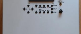
The welding output current control circuit allows you to adjust its value from small values for welding up to 160-200 amperes required when cutting with electrodes. She:
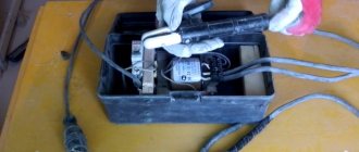
- made on a board from thick getinax;
- covered with a dielectric casing;
- mounted on the housing with the output of the adjusting potentiometer handle.
The weight and dimensions of the welding machine were smaller compared to the factory model. We placed it on a small cart with wheels. To change jobs, one person rolled it freely without much effort.
The power cord was connected through an extension cord to the connector of the input electrical panel, and the welding hoses were simply wound around the body.
Detailed Assembly Instructions
The circuit being considered for self-production is rather a hybrid option, since it involves the use of a power transformer in conjunction with electronics. The transformer in this case is used from among those that were installed in televisions of older models.
This is roughly the kind of power transformer you will need to make a homemade stabilizer design. However, the selection of other options or do-it-yourself winding cannot be ruled out.
True, TV receivers, as a rule, installed TS-180 transformers, while the stabilizer requires at least a TS-320 to provide an output load of up to 2 kW.
Step #1 - making the stabilizer body
To make the device body, any suitable box based on an insulating material - plastic, textolite, etc. is suitable. The main criterion is sufficient space for placing a power transformer, electronic board and other components.
It is also possible to make the body from fiberglass sheets by fastening individual sheets using corners or in another way.
It is permissible to select a housing from any electronics that is suitable for placing all the working components of a homemade stabilizer circuit. You can also assemble the case yourself, for example, from fiberglass sheets
The stabilizer box must be equipped with grooves for installing a switch, input and output interfaces, as well as other accessories provided by the circuit as control or switching elements.
Under the manufactured case, you need a base plate on which the electronic board will “lie” and the transformer will be fixed. The plate can be made of aluminum, but insulators should be provided for mounting the electronic board.
Step #2 - making a printed circuit board
Here you will need to initially design a layout for the placement and connection of all electronic parts according to the circuit diagram, except for the transformer. Then a sheet of foil PCB is marked along the layout and the created trace is drawn (printed) on the side of the foil.
Next, the board is etched using an appropriate solution (electronics engineers should be familiar with the method of etching boards).
You can make a printed circuit board for a stabilizer using quite affordable methods at home. To do this, you need to prepare a stencil and a set of tools for etching on foil PCB
The printed copy of the wiring obtained in this way is cleaned, tinned and all the radio components of the circuit are installed, followed by soldering. This is how the electronic board of a powerful voltage stabilizer is manufactured.
In principle, you can use third-party PCB etching services. This service is quite affordable, and the quality of the “signet” is significantly higher than in the home version.
Step #3 - assembling the voltage stabilizer
A board equipped with radio components is prepared for external wiring. In particular, external communication lines (conductors) with other elements - a transformer, switch, interfaces, etc. are output from the board.
A transformer is installed on the base plate of the housing, the electronic circuit board is connected to the transformer, and the board is secured to the insulators.
An example of a homemade relay-type voltage stabilizer, made at home, placed in a housing from a deteriorating industrial measuring device
All that remains is to connect the external elements mounted on the case to the circuit, install the key transistor on the radiator, after which the assembled electronic structure is covered with the case. The voltage stabilizer is ready. You can start setting up with further testing.
Simple design of DC welding machine
Based on the installation principle, the following parts can be distinguished:
- homemade transformer for welding;
- its power supply circuit is from network 220;
- output welding hoses;
- power unit of a thyristor current regulator with an electronic control circuit from a pulse winding.
Pulse winding III is located in power zone II and is connected through capacitor C. The amplitude and duration of the pulses depend on the ratio of the number of turns in the capacitor.
How to make the most convenient transformer for welding: practical tips
Theoretically, you can use any model of transformer to power the welding machine. The main requirements for it:
- provide arc ignition voltage at idle speed;
- reliably withstand the load current during welding without overheating the insulation from prolonged operation;
- meet electrical safety requirements.
In practice, I have come across different designs of homemade or factory-made transformers. However, they all require electrical engineering calculations.
I have been using a simplified technique for a long time, which allows me to create fairly reliable transformer designs of medium accuracy class. This is quite enough for household purposes and power supplies for amateur radio devices.
It is described on my website in an article about making a transformer soldering iron Moment with your own hands. This is an average technology. It does not require clarification of the grades and characteristics of electrical steel. We usually don’t know them and cannot take them into account.
Features of core manufacturing
Craftsmen make magnetic wires from electrical steel of various profiles: rectangular, toroidal, double rectangular. They even wind coils of wire around the stators of burnt-out powerful asynchronous electric motors.
We had the opportunity to use decommissioned high-voltage equipment with dismantled current and voltage transformers. They took strips of electrical steel from them and made two donut rings out of them. The cross-sectional area of each was calculated to be 47.3 cm 2 .
They were insulated with varnished cloth and secured with cotton tape, forming a figure of a reclining figure eight.
They began to wind the wire on top of the reinforced insulating layer.
Secrets of the power winding device
The wire for any circuit must have good, durable insulation, designed to withstand long-term operation when heated. Otherwise, it will simply burn during welding. We proceeded from what was at hand.
We received a wire with varnish insulation, covered with a fabric sheath on top. Its diameter - 1.71 mm is small, but the metal is copper.
Since there was simply no other wire, they began to make the power winding out of it with two parallel lines: W1 and W'1 with the same number of turns - 210.
Read also: Joining plywood into a tenon
The core donuts were mounted tightly: this way they have smaller dimensions and weight. However, the flow area for the winding wire is also limited. Installation is difficult. Therefore, each power half-winding was separated into its own magnetic circuit rings.
In this way we:
- doubled the cross-section of the power winding wire;
- saved space inside the donuts to accommodate the power winding.
Wire alignment
You can get a tight winding only from a well-aligned core. When we removed the wire from the old transformer, it turned out to be bent.
We figured out the required length in our minds. Of course it wasn't enough. Each winding had to be made from two parts and spliced with a screw clamp directly on the donut.
The wire was stretched along its entire length on the street. We picked up the pliers. They clamped the opposite ends and pulled with force in different directions. The vein turned out to be well aligned. They twisted it into a ring with a diameter of about a meter.
Technology of winding wire on a torus
For the power winding, we used the rim or wheel winding method, when a large-diameter ring is made of wire and wound inside the torus by rotating one turn at a time.
The same principle is used when putting a winding ring on, for example, a key or keychain. After the wheel is inserted inside the donut, they begin to gradually unwind it, laying and fixing the wire.
This process was well demonstrated by Alexey Molodetsky in his video “Winding a torus on a rim.”
This work is difficult, painstaking, and requires perseverance and attention. The wire must be laid tightly, counted, the process of filling the internal cavity must be monitored, and the number of turns wound must be recorded.
How to wind a power winding
For it, we found a copper wire of a suitable cross-section - 21 mm 2. We estimated the length. It affects the number of turns, and the no-load voltage necessary for good ignition of the electric arc depends on them.
Typically reference books recommend 60-70 volts. One experienced welder told us that in our case 50 would be enough. We decided to check it, and if it wasn’t enough, then increase the winding further.
We made 48 turns with the middle terminal. In total, there were three ends on the donut:
- middle - for direct connection of the “plus” to the welding electrode;
- the outer ones - to the thyristors and after them to ground.
Since the donuts are fastened together and the power windings are already mounted on them along the edges of the rings, the winding of the power circuit was carried out using the “shuttle” method. The aligned wire was folded like a snake and pushed through the holes of the donuts for each turn.
The middle point was unsoldered using a screw connection and insulated with varnished cloth.
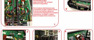
Reliable welding current control circuit
The work involves three blocks:
- stabilized voltage;
- formation of high-frequency pulses;
- separation of pulses into circuits of thyristor control electrodes.
Voltage stabilization
An additional transformer with an output voltage of about 30 V is connected from the power winding of the 220 volt transformer. It is rectified by a diode bridge based on D226D and stabilized by two zener diodes D814V.
In principle, any power supply with similar electrical characteristics of current and output voltage can work here.
Pulse block
The stabilized voltage is smoothed by capacitor C1 and supplied to the pulse transformer through two bipolar transistors of direct and reverse polarity KT315 and KT203A.
Transistors generate pulses to the primary winding Tr2. This is a toroidal type pulse transformer. It is made of permalloy, although a ferrite ring can also be used.
Winding of three windings was carried out simultaneously with three pieces of wire with a diameter of 0.2 mm. Made 50 turns. The polarity of their inclusion matters. It is shown by dots in the diagram. The voltage on each output circuit is about 4 volts.
Windings II and III are included in the control circuit for power thyristors VS1, VS2. Their current is limited by resistors R7 and R8, and part of the harmonic is cut off by diodes VD7, VD8. We checked the appearance of the pulses with an oscilloscope.
In this chain, the resistors must be selected for the voltage of the pulse generator so that its current reliably controls the operation of each thyristor.
The unlocking current is 200 mA, and the unlocking voltage is 3.5 volts.
Welding current regulation
Variable resistor R2, with its resistance, determines the position of each pulse passed through the control electrode of the thyristor. The shape of the pulsating current at the output of the power circuit of the welding machine depends on it.
Half-sine ripples can pass through completely when the welding current is set to maximum or be cut off to almost zero.
DIY welding
Today we’ll talk about welding machines. Some people are already practicing and welding with all their might, while others are still just collecting money to buy it. Although there is another option - to assemble the welding yourself. What is needed for a basic welder: at least a transformer. The task is to apply voltage to the primary winding and obtain a multiply increased current and lower voltage on the secondary. Consider the circuit of a simple DC welding machine. Fig.1.
Fig.1
The circuit has its advantages and disadvantages, but it is very simple, unlike the circuit of a modern inverter. To assemble the latter you need serious knowledge and equipment, and to assemble a welder according to the given figure, you just need the desire and the ability to buy the elements. Figure 1 shows • the core on which the primary and secondary windings are wound; • diode bridge of four diodes; • throttle; • a capacitor (for an amateur) is connected in parallel with the arc. This should not be done, because the capacitor accumulates energy and during the process of igniting the arc, it will “clack”. If you introduce a 10 W resistor with a resistance of 1-2 Ohms into the circuit, this will reduce the charging/discharging current. As a result, the capacitor will remain intact and the electrode will not stick.
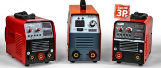
What types of transformers are there for welding machines:
- You can take a torus. This is the “donut” as shown in the photo. Its efficiency is 100%, its dimensions are small, at first glance there are some advantages, but not everything is so simple. It is more difficult to wind a toroid than an W-shaped transformer, which has only one coil on which all the windings are wound. Or a two-coil transformer, which actually has a lower efficiency.
So, let's say you assembled a transformer and got 50V at its output (see Fig. 1), connected a diode bridge, inductor, capacitor, etc. according to the scheme. We “strike” the electrode, ignite the arc - and we get a current of 150 ... 200A. And it’s good, you say, but it’s not that simple! Our transformer takes too much from the outlet... For example, with a current of 100A on the secondary winding, we will pull 5kW (≈25A) from the home outlet. If in the morning and even
During the day, this option may pass, but in the evening there will be surprises, because in the evening the tension begins to sag, accordingly, the light begins to “blink” - and expect dissatisfied neighbors to visit you.
We received 50V of alternating current at the output; to rectify it, a diode bridge is connected, which cuts off the negative current curve and transfers it to the positive ordinate system without loss of power.
The inductor serves to suppress ripples (smooth out current “jerks”). It accumulates energy and makes the current more “constant”; accordingly, the arc will burn more smoothly, without jerking. It accumulates energy and turns the current into a more “constant” one, which will allow the arc to burn more smoothly, without jerking. This inductor, in addition to R induction, has an active resistance, due to which a slight voltage drop is observed. “At idle” the capacitor is charged “to the root of two”: if there is 50V on the secondary winding, there will be about 70V on the capacitor. It is not involved in welding, but it makes it easier to ignite the arc, especially if you come across rusty metal that needs to be “pierced.”
Now let's talk about how to relieve the electrical system at home. You can install a ballast resistor (resistance), which will reduce the current that passes through the circuit, but it will generate heat that will warm the street. This is not beneficial for us. At a current of 100A, you get a two-kilowatt heater.
In order to reduce losses and avoid neighbors arguing, you need to reduce consumption. How to achieve this?
With a rigid current-voltage characteristic, the primary winding is wound as shown in Fig. 2. (two halves form a complete 220V winding.) A secondary winding is wound on top of it and connected to the previous one in parallel or in series.
Fig.2
Either we wind the windings with a thin wire and connect them in parallel, but with a large number of turns, or with a thick wire and connect them in series. (Fig. 3). In fact, we get the same thing in both cases: a rigid current-voltage characteristic, when we have half of the primary and half of the secondary wound on one coil. This type of trans is NOT SUITABLE for a welding machine!
Fig.3
You can install a throttle at the output, but this is like a “crutch”.
Better take a two-coil transformer. The greater the distance between its windings (how far apart they are), the less the resulting current. But you can use one more “trick”: wind a part of the secondary winding on top of the primary - this will reduce losses and increase the output current. It is clear that the losses on the coils will be different and one section will be rigidly connected in voltage, and the second will be “floating”. Using this principle, it is possible to construct a welding current adjustment. The primary winding is wound as is, then the secondary winding is 60-65%, and the rest of it is wound onto the “primary”. Such a device has a flat-sloping current-voltage characteristic. Why is she good? Since you will not be cooking with the transformer itself, but by connecting a rectifier and inductor to it, you need to compensate for the losses. If the characteristic is steeply falling, then, for example, from 100A the output will be 60A; if it is flattened, the losses are compensated (you can choose from a wider range of electrodes, use direct and reverse polarity).
When looking for elements, keep in mind that diodes must be used with a current of at least 100A, but better than 200A; place them on radiators. Experience shows that “screwing in” cheap Chinese 50A bridges is justified. Only if you need to get 200A at the output, you need to connect not 4 pieces of such bridges, but at least 8 pieces. If you take it with a reserve, only then everything will work well.
The inductor can be screwed onto almost any suitable magnetic circuit, the main thing is that it has a cross-sectional area of at least 10 square meters. cm. If you take 20 sq. cm - this will be even better and you will need to wind less media. It is also necessary to fulfill the following condition: the core should not be completely closed.
The size of the choke gap determines its inductance. With a small gap it will work well at low currents; if you increase it, you will get easy welding at high currents. Therefore, we need to look for a compromise.
Let's look at a few more schemes for “inquisitive minds”
Fig.4
Figure 4 uses a transformer with a rigid characteristic. Its output voltage is 36V. A capacitor is installed here, which increases the voltage to 45V and allows the arc to ignite. A resistor must be present. The diagram does not show the throttle, but you need to install it in any case, because cooking with it is much more pleasant and convenient.
In Fig. Figure 5 shows a diagram of an advanced swarApp. The property of resonance is used here. That is, we get an “LC circuit”: the inductance of the secondary winding and the capacitance of series-connected capacitors. And it all closes on an arc. The result is a transformer of relatively small dimensions and high power.
Fig.6
Collecting this beast is an interesting task, but very expensive! Capacitors C1-C20 are expensive. If you install some kind of slag, such as Chang, it will fly out immediately, but a good slag like JAMICON or JAVA costs money. Pay attention to the presence of hard leads.
If the voltage on the secondary winding of the transformer is, say, 30-40V, then you need to take 1.5-2 times more U conductors according to the circuit. If this condition is not met, the capacitors will break through and burn out.
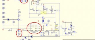
There is a circuit of a thyristor regulator (Fig. 7), it has a primary winding, a secondary winding and a control winding. A pair of powerful thyristors and diodes is also used. Winding III is designed for U from 30V to 40V, current about 1 A.
Fig.7 Click on the picture to open
Resistor R1 is designed to adjust the welding current, i.e. if you need to set the minimum range. R2 works as the main one (that is, R1 can be removed).
R3 limits the thyristor control current.
Zener diode V06 can be installed both domestically and imported.
Instead of the KU101 thyristor, you can take the 202nd, starting with almost any letter.
KD209 diodes can be replaced with any for current up to 1 A
Controlling the opening angle of the thyristor regulates the power: the less it is open, the less current at the output. If you open the thyristors completely, they will work like diodes and you will get a full-fledged diode bridge - welding under this condition will work well, but if the power is reduced by more than half, the current ripple will increase, and welding will be quite difficult. Therefore, it is better to add a choke to the circuit.
Personal impressions of use
When the DC welding machine was made with our own hands, we began to study its capabilities. First of all, we experimented with the polarity of the electrode connection and identified a pattern.
The electrode can be supplied with “plus” - direct polarity or “minus” - reverse polarity. In this case, the depth of weld penetration changes. With reverse polarity it increases by about 40-50%.
Our welding machine allows you to weld with 3 mm electrodes, providing a welding current of 80 amperes for quite a long time. The heating of the structure does not exceed operating conditions. At the same time, the load in the household wiring network is maintained at a level of up to 20 A.
If there is a need to use 4 mm electrodes or increase the welding current, then it is necessary to organize breaks in work to cool the machine. Ours is natural: due to cracks and holes.
The cooling system can be enhanced by forced ventilation by blowing. But we did not deal with this issue.
I show the scanned handwritten text of a preserved document. It may be useful for repetition.
And now I recommend watching the video by the owner of zxDTCxz “Welding machine based on a toroidal magnetic core.” It contains many useful recommendations.
If you still have questions on the topic, then ask them in the comments, I will answer.
- 5
- 4
- 3
- 2
- 1
(5 votes, average: 5 out of 5)
Subscribe to our “Home Master” newsletter and you will always be the first to know about the news from this blog!
Stabilization of household voltage
The desire to provide stabilized voltage to the household network is an obvious phenomenon. This approach ensures the safety of the equipment in use, often expensive and constantly needed on the farm. And in general, the stabilization factor is the key to increased safety in the operation of electrical networks.
For domestic purposes, a stabilizer is most often purchased for a gas boiler, the automation of which requires connection to a power supply, for a refrigerator, pumping equipment, split systems and similar consumers.
Industrial design of a mains voltage stabilizer, which is easy to purchase on the market. The range of such equipment is huge, but there is always the opportunity to make your own design
This problem can be solved in different ways, the simplest of which is to buy a powerful voltage stabilizer manufactured industrially.
There are a lot of offers of voltage stabilizers on the commercial market. However, purchasing options are often limited by the cost of devices or other factors. Accordingly, an alternative to purchasing is to assemble a voltage stabilizer yourself from available electronic components.
Provided you have the appropriate skills and knowledge of electrical installation, the theory of electrical engineering (electronics), wiring circuits and soldering elements, a homemade voltage stabilizer can be implemented and successfully used in practice. There are such examples.
Stabilization equipment made with your own hands from available and inexpensive radio components may look something like this. The chassis and housing can be selected from old industrial equipment (for example, from an oscilloscope)
Hello. What if the transformer is W-shaped? Can you advise? I'm assembling a welding machine.
Hello, Alexander. The operating principle is the same. However, send photos to the site’s email (see section “About the site”) and describe the dimensions of the magnetic core iron. This will help me make a power calculation. Also read the comments to the article about the design of the homemade Moment soldering iron. There I devoted a lot of time to this issue. You will need it.
Read also: Homemade ax made from springs
Hello Dear Alexey! Thank you for your article, very useful and interesting! Tell me, I have a couple of questions! My initial power source is already ready 36 volts DC, if I exclude the very beginning of the so-called transformer from this circuit, will this circuit work? Or is it not suitable for me? Need something else? I'll be looking forward to your answer! thank you in advance!
Hello, Pavel. I didn't quite understand your question. Let's clarify: you have a ready-made voltage source that gives an output of 36 volts. Did I understand correctly that you want to use it to make a DC welder? For reliable arc ignition you need 60-70 volts. In my case, it turned out to light it from 50. I didn’t experiment below, try it, but it’s unlikely that you’ll get anything good... One more important electrical characteristic is the output power. If this is not provided, the welding machine will simply burn out. I created it at 50Vx160A=8kW. Pay attention to the power circuits of your source, will they withstand such power? Actually, I advise you to do the calculation based on the initial problem: what electrodes are you going to use to cook and cut. It is necessary to create an electric arc current under them and ignite it. This will determine the output power of the welder. The design is calculated and parts are selected based on these parameters. Send us a photo of your unit. Or better yet, a diagram. Then it will be possible to give more specific recommendations.
Victor, the ignition voltage depends on the characteristics of the welding electrode. With the right choice of electrode, welding work goes well at Ux.x. welder 36 volts or less.
Thanks for the addition. Alexander. Pavel has already explained this to me too. I'm just not a welder, but a simple electrician.
I work as a welder in the north, I travel urgently to emergency situations! Situations often began to occur when the welding generator needed to be dragged directly into the swamp or to perform certain welding jobs - this was very difficult and sometimes extremely impracticable! But I go to the site on a tracked all-terrain vehicle with 24 volt batteries installed. It is not difficult to remove them and quickly bring them to the place! 24 volts does not cook well, but when connecting the battery. up to 36 volts cooks perfectly! but last week a situation happened that I tried to weld the break for too long and my battery exploded! Dear Alexey, I ask you to help me in this matter because after reading your article I realized that you are a professional in this matter! Is it possible to adjust your circuit to 36 volts DC, or 24 if necessary, I can connect two to 48 volts
Well, I use 2.0 and 2.5 mm electrodes, sometimes I use 3 mm. current for them from 70 to 110 amperes for the eyes 36 volts cooks well, well, more precisely, it cooked! As you understand, it was shorted to a straight line! I understand that, of course, this is nonsense and everything should be correct and according to science! That's why I turned to you! 110 is even a lot, rarely when I set it to more than 100 it means 70-100 amperes
Pavel, doing welding from a battery assembly is not the best option, but it works quite well for emergency situations. We must take into account the risk of losing the battery. What needs to be taken into account in my opinion: 1. All banks must be well charged. Any defective bank will work to discharge the battery, taking its current onto itself. 2. Welding must be done quickly. Otherwise, the electrolyte will boil and the battery will explode. Before my eyes, while serving in the army, a mechanic driver of a self-propelled tractor dropped a wrench about 22x24 in size onto the battery output tires. The arc was such that the key burned out, but the banks survived. They started a diesel engine with 500 horses. I don’t remember the amps, but the assembly was made from tank batteries. It was difficult to drag them even with two people. I return to our welding. We assume that the maximum current should be 110 amperes. It should be issued by the battery. A voltage of 48 volts should be sufficient. If you worked from 36, then you can also use it, but 48 is better. The mode of short circuiting batteries through the electrode is not very good. It must be limited by electrical resistance. For DC circuits, I recommend using a CMOS series bipolar transistor. The control circuit that I made for a welder using rectified current will not work. Here it is pure constant and everything works differently. I’ll think about the scheme tomorrow and propose something that, in my opinion, is most suitable.
Pavel, I haven’t found a decent circuit that a beginner with minimal electronics skills can assemble. Many mistakes can be made. I propose to connect an inverter to the battery, converting constant voltage into 220 volts, and power the welding inverter from it. All this equipment can be simply purchased. The heating of the electrolyte in batteries must be controlled; it must not be allowed to boil.
Good day Pavel, I have such a device as ISKRA Universal vd 0801 knot. I encountered this factor while working. During operation, it buzzed very loudly and the diodes flew out. I replaced all 16 diodes with new ones. turned it on and inserted the jumper into the block. and everything happened again. what could be the problem. There is very little said on the Internet about such a device, maybe you can help. thank you in advance
Hello, Ivan. I have not encountered such a device, there is no diagram. What I found on the Internet raises doubts and requires verification. However, we have experience with repairing such devices. I think we'll repair it. I need a diagram and detailed photos. Send what you have to the site's email. I will get acquainted with the design and tell you what to do. You will need a multimeter or an old tester for electrical measurements. Battery, flashlight bulb. wires. I'm waiting for additional information.