To ensure that the power supply in your homes is always of high quality, uninterrupted and reliable, it is very important to correctly connect the wires during installation work. There are a lot of methods, we will consider each in detail separately with its advantages and disadvantages, with step-by-step instructions for performing switching. We will also pay attention to the eternal question of electricians - how to connect wires whose cores are made of different metals (for example, copper and aluminum).
Removing the insulating layer from the wires
I would like to immediately dwell on a question that will be common to any method. Before connecting the wires into a common electrical unit, they must be stripped of the top insulating layer.
This can be done using a mechanic's knife. This method is simple, but there is a high probability of damage to the conductor. To do everything correctly, you must strictly follow the step-by-step instructions:
- Place the wire on some flat surface (such as a table).
- Press it with your left index finger.
- With your right hand, take the knife and lightly press it into the insulating sheath of the wire. To avoid snagging the metal core, position it towards the cut at an angle. If the angle is right, there is a possibility of a circular cut in the core, as a result of which it may subsequently break.
- Hold the knife in this position. Using the index finger of your left hand, slowly twist the conductor one full turn, thus cutting the insulation around the entire circle.
- All that remains is to pull off the cut piece of insulation.
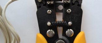
Professional electricians now necessarily have in their arsenal such a device as a stripper. This is a multifunctional tool that can be used to strip insulation from a wire or cut a cable. It can be simple, semi-automatic or automatic. The most important thing is that when stripping the insulation with a stripper, the conductor is not damaged. For each standard core diameter, such a tool has a calibrated hole with a cutting edge.
The length to which wire cores need to be stripped is different for each connection method.
How to find out the cross section
The main technical characteristics of conductors: cross-section, diameter and other important properties are indicated in catalogs or corresponding descriptions. However, if the contractor does not have the opportunity to familiarize himself with this data, and the question of how to determine the cross-section of the welding cable needs to be answered, then you should remember some recommendations.
There are several ways to determine the cross-section of a conductor. They all boil down to the fact that first you need to calculate the diameter of the core. This can be done using a micrometer or caliper. However, the simplest method, which does not require special accessories, is to use the following method.
The contractor will need to remove the insulation from the conductive core. Then you need to wind the core around a cylindrical object (screwdriver) and use a ruler to measure the total length of the turns, the number of which for accurate calculations should exceed 10. In conclusion: the total length in mm. must be divided by the number of turns. The resulting value will be the diameter of the wire, from which the cross-sectional value can be found.
The contractor can find complete information about the cross-sections of cables of various brands in articles devoted to this topic:
Twist
Let's start with the simplest and most well-known method - twisting. It can also be called the oldest; it’s not for nothing that electricians call twisting the “old-fashioned method.”
We will not tell you that such a connection of wires is durable and reliable. According to the main document in electrical engineering, PUE (“Rules for Electrical Installations”), twisting is generally prohibited, despite the fact that half a century ago it was used everywhere. The fact is that in those days the load in the apartments consisted only of lighting, radio or television. If you consider the current load in modern apartments with a huge amount of household appliances used daily, then no old insulation, core cross-sections and methods of connecting wires are any longer suitable.
Nevertheless, we will talk about twisting, and even first of all, because it is the main stage of such connection options as welding and soldering.
Positive sides
The most important advantage of twisting is that it requires absolutely no material costs. All you need is a knife to remove the insulating layer from the wire cores and pliers to make the connection.
The second indisputable advantage of twisting is its ease of execution. You don’t need any special knowledge or skills; it can be done by anyone who has ever held pliers in their hands.
Several wires can be connected simultaneously in a twist, but their total number should not exceed six.
Negative sides
The main disadvantage of twisting is its unreliability; it weakens over time. This is due to the fact that there is residual elastic deformation in the cable or wire cores. At the point of twisting, the contact resistance increases, which can lead to contact failure and heating. In the best case, you will detect this in time and re-seal the connection; in the worst case, a fire may occur.
Electrical wires made of different metals cannot be connected using twisting. As an exception, you can twist copper and aluminum wire, but only if the copper core is first tinned with solder.
In electrical engineering there are concepts of detachable or permanent connection. So twisting does not apply to one or the other. A detachable connection is characterized by the fact that its ends can be disconnected many times. This cannot be fully done in twisting; every time after the next unwinding and twisting of the cores, they will deteriorate. It is also impossible to call twisting a permanent connection, because it does not contain the concepts of strength, reliability and stability necessary for this. This is another disadvantage of the twist connection.
Installation
If for some reason you do not have the opportunity to use other methods of connecting electrical wires, you can use twisting, just do it well. Very often it is used as a temporary option and is subsequently replaced by more reliable switching methods.
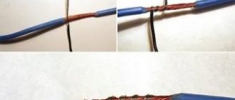
How to connect wires using twist? To begin with, the cores are stripped to 70-80 mm. The main thing is to twist all switched conductors into one single twist at the same time, and not wind one around the other.
Many people mistakenly begin to twist the wires together from the place where the insulating layer ends. But it is better in this place to clamp both wires with one pair of pliers, and with the other, grab the ends of the wires and perform rotational movements in a clockwise direction.
If the wire cross-section is small, you can twist it by hand. Align the conductors along the cut of the insulation and hold them firmly in this place with your left hand. Bend all switchable ends into one single bend at an angle of 90 degrees (a bend length of 10-15 mm will be enough). Hold this bend with your right hand and rotate clockwise. This must be done firmly and firmly. If it is already difficult to twist your hands at the end, use pliers as described above. As soon as the twist becomes smooth and beautiful, you can trim the bend.
You can connect several wires this way, but then to make it easier to twist them, make the bend longer, somewhere around 20-30 mm.
How to properly twist wires is shown in this video:
There is also a way to twist wires using a screwdriver, see about it here:
For information on twisting wires using a special tool, see here:
Now the resulting twist must be carefully insulated. Electrical tape is used for this. Do not spare it, wind it in several layers, and insulate not only the connection itself, but also step 2-3 cm over the core insulation. This way, you will ensure the insulating reliability of the twist and protect the contact connection from moisture.
You can also insulate the connection of wires using heat pipes. The main thing is not to forget to put the tube on one of the cores to be connected in advance, and then push it into the place where it is twisted. When exposed to heat, the thermal tube shrinks, so slightly heat its edges and it will firmly grip the wire, thereby providing reliable insulation.
If the twisting is done well, there is a chance that it will serve you for many years, provided that the load current in the network is normal. But it’s still better not to stop at this stage and strengthen the joint by welding or soldering.
Subscribe to the newsletter
How to properly connect cables to a welding inverter
A welding machine is equipment that can be used to convert the current and voltage that are necessary to produce an arc between the electrode and the metal being welded. First of all, in the process of high-quality operation of a welding machine, the main factor is its power. So, for example, for welding gratings or fences, an electrode of up to 4 mm will be sufficient; the welding current will fluctuate between 180-220 amperes. The open circuit voltage (Ux.x.) also plays a significant role. It is believed that the higher the voltage, the easier it is to ignite the arc. Often the no-load voltage is 30-80 V. The welding machine also has a current adjustment lever, with which you can increase or decrease the current. Basically, welding machines are designed for 220 or 380 V, and this must be taken into account when connecting the welding machine. If you have a single-phase welding machine, then the welding cable is connected to the power supply in the following order - one wire per phase, the second to the neutral, and the third to the protective zero. The cables are connected in the same way if you have a three-phase welding inverter, but with one condition - you use a 5-core cable, 3 of which are connected to terminals L1, L2 and L3.
You can lengthen the welding cable on the inverter, taking into account the voltage loss and, accordingly, the current strength. The longer the cable, the higher the current must be set at the output. The technical documentation of some devices indicates a categorical prohibition on extending the welding cable. When connecting cables to the Resanta welding machine, you need to keep this in mind. In practice, the performance of other devices does not noticeably deteriorate when the cables are extended to 5-6 meters. This is due to the power reserve and resource built into the welding machine by the manufacturers. In any case, connections on the welding cable are not allowed. The short cable is replaced with a longer piece with appropriate terminations.
How to choose welding equipment
Today, manufacturers offer a large selection of welding equipment. And in order to choose the best option, you must at least have an idea of what devices are available, what characteristics you should pay attention to, and what you need to know to properly connect the purchased device.
The range of welding machines is huge, but the main choice consists of:
• welding transformers; • welding rectifiers; • inverters.
There is a completely incorrect statement that the heavier and larger the device, the better - dimensions and weight do not determine its functionality. The weight of a conventional transformer does not exceed 30 kg, a welding rectifier - 20 kg, and an inverter - 10 kg. Naturally, the prices for the devices will be different.
One of the main conditions that you need to pay attention to is the parameters for welding current, PVR (percentage of operating time) or PV (on duration). To count the time, use an interval of 15 minutes. A large number of devices have a fairly convenient arc ignition option. As for devices with welding current rectification, they produce a very high-quality seam, have engine starting functions, charge a battery, and heat and straighten the metal using a carbon electrode.
The question often arises: is it possible to connect a welding machine through a meter? It should be taken into account that new household meters are designed for a current of 40-50 amperes, and this equals
8 kW active power. Therefore, it is necessary to select a welding machine that will consume a current less than that indicated on the meter and the rating of the input circuit breaker. If the rated current of the welding machine is selected correctly, the electric meter will not be affected.
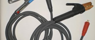
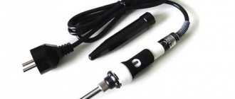
Cable for welding machine (cable for welding).
For productive operation of the welding machine, it is necessary to select a welding cable so that its cross-sectional area, length and voltage drop of the welding circuit do not exceed 2 W. The KG welding cable is an insulated flexible current conductor with one or more cores woven from copper wires of various diameters (from 0.18 mm to 0.2 mm). Such a cable performs the function of supplying current from the welding machine or voltage source to the device with which the electrode is held.
Soldering
Soldering is when electrical wires are joined using molten solder. This type of connection is most suitable for copper wires. Although there are now various fluxes for aluminum, experienced electricians prefer to refrain from such soldering. But if necessary, you can use special fluxes and even solder copper and aluminum.
Positive sides
This type of connection cannot be compared with twisting; soldering is much more reliable (in terms of reliability it is second only to welding).
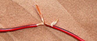
Using soldering, you can connect stranded and single-core wires, as well as wires of different sections.
This type of connection does not require any maintenance throughout the entire period of operation.
Soldering is considered low in cost, the only equipment you need is a soldering iron, and flux and solder are very inexpensive, and their consumption is quite negligible.
Negative sides
The disadvantages of this method include high labor intensity. Soldering requires certain preparatory work; wire strands must first be tinned before twisting. The surfaces to be soldered must be free of oxides and absolutely clean before starting work.
And of course, you need experience in using a soldering iron, that is, the person who will connect the wires using the soldering method must have a certain qualification. After all, during the soldering process it is very important to maintain the required temperature conditions. An underheated soldering iron will not heat the connection well; overheating is also unacceptable, because the flux will burn out very quickly, not having time to do its job.
Soldering is a slow process, but this disadvantage is compensated by the reliability of the contact connection.
Installation
The step-by-step soldering process is as follows:
- Remove the insulation from the cores by 40-50 mm.
- Sand the bare areas of the wires until they shine using sandpaper.
- Dip a heated soldering iron into rosin and move it over the cleaned surfaces several times.
- Perform a twist.
- Bring the soldering iron tip to the solder.
- Now immediately heat the twist with solder, the tin should melt and fill the gaps between the turns.
- Thus, the entire twist is enveloped in tin, after which it is allowed to cool.
- Wipe the hardened solder with alcohol and insulate it.
Soldering wires with a soldering iron is shown in this video:
Soldering wires using a gas soldering iron:
Soldering twists by immersion in molten solder:
Welding
In order for the connection of electrical wires to be as reliable as possible, the considered twisting method must be subsequently secured by welding. It is similar to soldering, only now a welding machine is used instead of a soldering iron.
Positive sides
This method is most preferable to all others, since it meets all regulatory requirements in terms of reliability and quality.
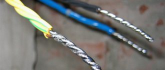
The welding method is based on contact heating of the ends of the wires with a carbon electrode until a ball (contact point) is formed. This ball is obtained as a single unit from the fused ends of all connected cores, which ensures safe and reliable contact; it will not weaken or oxidize over time.
Negative sides
The disadvantage of welding is that such work requires certain knowledge, experience, skills and special equipment; you often have to turn to specialists.
Installation
In order to connect wires using welding, you will need the following devices, tools and materials:
- welding inverter with a power of at least 1 kW, its output voltage must be up to 24 V;
- carbon or graphite electrode;
- goggles or eye mask;
- welding leather gloves to protect hands;
- a mechanic's knife or stripper for removing the insulating layer from conductors;
- sandpaper (for cleaning the conductive surfaces to be connected);
- insulating tape for further insulation of the welding joint.
The sequence of work is as follows:
- Free each connected wire from 60-70 mm of insulation.
- Sand the exposed wires until they are shiny using sandpaper.
- Twist, after biting, the length of its ends should be at least 50 mm.
- Attach grounding clamps to the top of the twist.
- To ignite the arc, bring the electrode to the bottom of the twist and lightly touch the connected wires with it. Welding happens very quickly.
- It turns out to be a contact ball, give it time to cool, and then insulate it with tape.
As a result, an almost solid wire is obtained at the end, that is, the contact will have the lowest transition resistance.
If you connect copper wires in this way, then choose a carbon-copper electrode.
I would like to recommend that if you purchase a welding machine (it will be useful not only for connecting wires, but also for many other purposes), then choose the inverter option. With small dimensions, weight and electrical energy consumption, it has a wide range of welding current adjustment and produces a stable welding arc. And this is very important to be able to regulate the welding current. If you choose it correctly, the electrode will not stick and the arc will hold steady.
Watch how welding is done in this video:
We looked at the main types of wire connections. Now let’s briefly talk about methods that are used less frequently, but also guarantee quality and reliability.
Crimping
For this method, special tubular sleeves or lugs are used, with which the wires to be connected are crimped and crimped. The essence of the method is the joint deformation of the sleeve and the cores inserted into it. When deformed, the sleeve contracts and puts pressure on the conductive surfaces. The conductors engage in mutual adhesion, which ensures reliable electrical contact.
The advantage of such a connection is its reliability, and also the fact that it can be classified as “set and forget”; it does not require maintenance.
But along with the positive aspects, crimping also has a number of disadvantages. First, a special tool is required (a crimping press or mechanical or hydraulic pliers). Secondly, the quality of the connection directly depends on the correctly selected sleeve (it is selected depending on the number of cores being connected and their cross-section).
Before connecting two wires using crimping, they are not only stripped of insulation, but also lubricated with a special paste. Aluminum is treated with quartz-vaseline paste; it removes the oxide film and prevents it from appearing again. For copper conductors, quartz impurities are not needed; technical petroleum jelly is sufficient. It is needed to reduce friction. Lubrication also minimizes the risk of damage to the cores during deformation.
Next, the cores must be inserted into the sleeve until they mutually stop, and alternate crimping is performed on both sides. The pressed joint is insulated using insulating tape, varnished cloth or a thermal tube.
How to connect wires with sleeves is shown in these videos:
Connecting the welding cable with connectors
The simplest and most effective method of connecting welding conductors is the method using connectors. To do it correctly, you need to choose wisely:
- welding cable brands,
- connectors,
- tips,
- plugs and terminals.
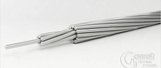
The choice of cable connector depends on the conductor cross-section. The latter can be determined using a micrometer or caliper. The connector can have an area of 10, 25, 35...120 mm2. There are two designs of devices - pin (“male”) and female (“female”). To connect them to the equipment, you need special sockets that act as a response component of the plug.
When purchasing lugs, you need to pay attention to the standard size (must correspond to the cross-sectional area of the wire) and materials of manufacture. Preference should be given to products with chrome plating, which prevents oxidation.
The crimp connection is extremely simple. It consists of stripping products of insulation, combining cores into bundles, putting on connectors and clamping them.
Bolted connection
Bolts for connecting wires used to be often used, now this method is more characteristic of circuits with high voltage. The contact is reliable, but the electrical unit connected in this way is too cumbersome. Until recently, large distribution boxes were installed in apartments; at least somehow, such a connection could be placed in them. Modern boxes are smaller and are not designed for switching wires using this method.
But you definitely need to know about it, because this is one of the ways to solve the eternal problem of connecting conductors made of different metals. The bolt contact is ideal for switching completely incompatible cores - thin and thick, aluminum and copper, single-core and stranded.
The wire strands must be stripped and the ends twisted into rings. A steel washer is put on the bolt, then the rings of the wires to be connected are put on (this is the case when they are made of homogeneous metal), then another steel washer follows and everything is tightened with a nut. If aluminum and copper wires are connected, another additional washer must be placed between them.
The advantages of this connection are its simplicity. If necessary, the bolted structure can always be unscrewed. If necessary, you can add more wire strands (as long as the bolt length allows).
The most important thing in this type of connection is to prevent direct contact between copper and aluminum, and do not forget to place an additional washer between them. And then such a switching unit will serve for a long time and reliably.
Modern technologies
In many cases, the methods discussed are gradually becoming a thing of the past. They were replaced by factory wire connectors, which made installation and switching work much easier and faster:
- Terminal blocks, inside of which there are tubular brass sleeves. Stripped wire strands are inserted into these tubes and secured by tightening the screws.
- PPE caps, inside of which there are compression springs. The cores are inserted into the cap and then turned clockwise with little effort, thereby reliably compressing the connected wires inside.
- Self-clamping terminals. It is enough to place the wiring in them, and there it is automatically fixed due to the pressure plate.
- Lever-type terminal blocks. This connecting element is reusable. It is enough just to lift the lever, insert the conductor into the contact hole and lower the lever back, reliable fixation is ensured.
We do not talk in detail about all existing terminal blocks, since there is a separate article about this, where each type of wire clamp is discussed in detail.
We hope that we have clearly explained to you how to connect the wires correctly. Choose the method that suits you best. When choosing, take into account the cross-section and material of the conductors, the location of the connection (outdoors or indoors), and the amount of load current that will flow in this electrical circuit.
How to hold it in a holder
The method of fixing the welding cable depends on the type of electrode holder : homemade or purchased (produced by companies of the corresponding profile).
Types of homemade holders and methods of assembling them, their main advantages and disadvantages are discussed in the article “Electrode holder for a welding machine.” This article also presents a method for correctly and securely connecting the cable to the electrode holder.
You should also pay attention to the recommendations of the master , who will help you make a professional, competent holder yourself. For clarity, a video of the assembly of the holder is presented.
To understand how to connect welding cables to the purchased holder , we recommend that you watch the video below. The performer can clearly see that the cable, together with a metal gasket (plate), is inserted into the corresponding hole and securely fixed with a key by tightening the screws.