02/01/2022 Author: VT-METALL
From this material you will learn
:
- Requirements for weld parameters
- Methods for calculating the length of the weld and other connection parameters
- Calculation of the length of the weld based on the mass of the metal
- Calculation of weld leg length
The length of the weld is one of the parameters that affects the strength of the entire joint. When calculating a joint, it is necessary to take into account many factors: the type of metal, the mass of the parts being welded, stress, etc. Only after this can the length and other characteristics be determined.
Depending on the type of parts and the method of their connection, approaches to calculating the length will vary. In our article we will tell you how to calculate this parameter, what affects the calculations and what requirements are imposed in regulations.
Weld bead width according to GOST
Published by: Anton Churakov In welding practice, in regulatory and technical documentation, there are some disagreements in the requirements for the implementation of facing and filling layers.
In this publication we will consider and conduct a small analysis of the requirements for the width of the rollers. In the technical literature and regulatory documents there are several meanings of the terms: narrow, thread, stringer, widened, wide seam, pass, roller. The definitions of these seams, as well as the transverse dimensions, vary from source to source. As an example, you can read the following excerpts from various sources.
- RD 558-97 Guidance document on pipe welding technology during repair and restoration work on gas pipelines:
clause 3.2.21. With the elliptical form of processing the defective area (Fig. 1.3), regardless of the strength of the metal, the first surfacing layer, filling layers, contour layer, and facing layer are performed. Welding is carried out with electrodes with a diameter of 2.5-3.25 mm and narrow beads (“stringer seams”) 8-12 mm wide.
- Solntsev Yu.P. “Metals and alloys. Directory":
Stringer bead - Narrow bead.
A bead of continuous weld without noticeable variation in the cross section. Unlike a wavy seam.
clause 7.14.9. In the cases specified in paragraphs. 7.14.7 and 7.14.8, repair of welded joints (surfacing of beads) should be carried out using welding technologies as for joints of different thicknesses of the same diameter with the implementation of thread (stringer) seams to ensure a smooth transition from the welded joint to the base metal.
clause 3.12. Thread bead: A single weld made without transverse vibrations and applied to the main pipe or to the end of the coupling when welding corrosion and mechanical damage, as well as installing welded repair structures (couplings, reinforcing linings and pipes).
clause 7.1.5. Welding pipe joints into a narrow groove with an edge bevel angle of 7° (type Tr-3a according to Table 6.2) in order to avoid slagging and lack of fusion in the root part of the weld should be performed as follows:
the root layer is applied with a thread suture without oscillatory transverse movements of the electrode; electrode diameter – no more than 3 mm;
clause 13.2. Welding joints of pipes made of austenitic steels should be carried out with minimal heat input. To this end, you should:
manual arc welding should be carried out almost without transverse vibrations of the electrode using narrow beads with a width of no more than three diameters of the electrode; with an electrode diameter of 2.5 mm, the height of the roller should be 2.5 - 4 mm, with an electrode diameter of 3 mm, the height of the roller should be 3 - 5 mm.
- Welding in one pass is preferable when the seam width is no more than 14-16mm, because gives less residual deformation. When the metal thickness is more than 15 mm, welding each layer “through” is undesirable. The first layer has time to cool, and cracks appear in it [Losev V.A., Yukhin N.A. — Illustrated welder's manual]
- Bead - Weld metal, deposited or remelted in one pass [GOST 2601-84 Welding of metals. terms and definitions of basic concepts]
- Widened bead - a bead obtained by welding with transverse vibrations of a welding wire or welding tool [GOST R ISO 857-1-2009. Welding and related processes. Dictionary. Part 1. Metal welding processes. Terms and Definitions]
- Bead/pass - a bead obtained by welding without transverse vibrations of the welding wire or welding tool [GOST R ISO 857-1-2009. Welding and related processes. Dictionary. Part 1. Metal welding processes. Terms and Definitions]
- Narrow bead - a weld bead formed without noticeable lateral movement;
- Flared Bead - For a manual or semi-automatic process, a weld bead formed by a reciprocating transverse motion. See also oscillation
- Narrow roller; stringer bead - A bead deposited without lateral vibration of a filler rod or welding tool [CEN/TR 14599:2005 - Welding terms and definitions in accordance with EN 1792]
- Wide bead (weave bead) - A bead deposited by the transverse vibration of a filler material rod or welding tool [CEN/TR 14599:2005 - Welding terms and definitions in accordance with EN 1792]
- If the longitudinal movement of the electrode is carried out without transverse vibrations, then the width of the roller is usually: b = (0.8 ÷ 1.5) del. Such rollers are used when making the first layer of a multi-pass weld, when welding thin metal, and also when welding with a thick coating resting on a cover. A normally formed single-pass seam in most cases should have a width b = (2 ÷ 4) del. [Dumov S.I. – Electric fusion welding technology]
- A narrow bead is applied when welding the root of a seam, welding thin sheets and other cases. The slower the welder moves the electrode along the seam, the wider the bead becomes. Typically, when welding with thin-coated electrodes, the width of the narrow bead ranges from 0.8 to 1.5 times the diameter of the electrode rod. With a narrow but high bead, the volume of deposited metal is small, it hardens faster and unreleased gases dissolved in the metal make the weld porous. Therefore, widened rollers are more often used. The best welding quality is obtained with a bead width equal to 2.5 - 3 times the diameter of the electrode. [Glizmanenko D.L. — Welding and cutting of metals]
In the regulatory and technical documentation, the requirements for the width of the facing and filling beads of a welded joint are given in a very small volume. The table below is taken from Recommendations for the use of RD 03-615–03.
Excerpts from documents recommending welding of the facing and filling layers in several beads:
OST 36-57-81 Steel technological pipelines made of carbon and alloy steels for pressure Ru up to 9.81 MPa (100 kgf/cm2). Manual argon arc welding. Typical technological process. Clause 2.4.22 Table 4.
Notes. The beads of welds made using the argon arc method are shaded.
The numbers indicate the sequence of application of beads in the layers of the weld
RD 558-97 Guiding document on pipe welding technology during repair and restoration work on gas pipelines. Table 2.10
Having analyzed information from various sources, I have conditionally identified three types of beads in relation to RD welding:
1) Thread / narrow bead - a bead applied without lateral vibrations of the electrode or welding tool.
Most often used for welding the root layer, welding austenitic steels, welding thin workpieces, performing surfacing work and undercut welding.
2) Widened roller – a roller up to 14 mm wide (on average no more than 3 electrode diameters).
Most often used for welding fillet welds, horizontal welds, thick-walled structures, and welding austenitic steels.
Geometric dimensions of the weld
A crystallized piece of molten metal formed at the junction of two metal parts or structures is a classic welding seam, which has certain geometric dimensions both in cross-section and in length. They depend on the type of connection, the welding method, the geometry of the cutting of the end edges of the products being joined and some other factors. These elements of welded parts are divided into two types: butt and corner. They should not be confused with the types of welding joints that are classified as butt, fillet, tee, and lap joints.
In all such structures there are working seams, which are subject to the main loads of the connection. The strength of the entire structure as a whole depends on the correct calculation of these connection elements. The quality of welding is influenced by many factors, including geometric characteristics such as width, length, concavity, convexity and other features of joining parts. For parts connected at right angles, the main geometric parameter is the size of the weld leg, on which the welding strength depends.
How to measure a seam leg
Measurements allow you to control the quality of work during its implementation or upon completion. They make it possible to objectively evaluate the result obtained and determine at what stage mistakes were made.
The size of the joints is determined based on geometric formulas. To obtain the result, it is necessary to calculate the leg of an equilateral triangle of the maximum size that can be inscribed in the cross-section of the connected elements.
Calculations can be done in different ways. When choosing an option, the welding method is taken into account. For example, if there is an overlap and two metal sheets 4 mm thick are connected, then the leg will also be approximately the same thickness. In other cases, the size of the leg is approximately 40% of the metal thickness.
Regulations
The main document regulating the geometry of welding seams is GOST 5264-80, according to which the main geometric characteristics are calculated using mathematical formulas. The cross-sectional dimensions and lengths according to GOST 5264-80 depend on the type of connection, the thickness of the structural parts, and the geometry of the processing of the end edges. In addition, when calculating the geometric parameters of welding joints, other regulatory documents are taken into account: SNiP II-23-81, instructions and technical regulations. Among all the geometric characteristics of welds, the main ones are the minimum length, width, depth, leg size and some others.
We understand the drawings of welding seams according to GOST
If you say that GOST is your favorite word, hardly anyone will believe you. But if you are engaged in welding and claim to be a high-class professional, you will have to treat this word with all respect, if not love it.
You need to not only respect him, but also have a good understanding of the required state standards regarding the typology of welding methods. Why? Because if you are working with something more serious than an old basin at the dacha, you will definitely come across working drawings with huge quantities of icons, letters and abbreviations.
That's right, without technical specifications and standard designations - nowhere. Modern welding technologies are a wide range of very different methods with their own requirements and technical nuances. All of them fit into several standards, which we will now go through and consider in the most careful manner.
Welding designations on GOST drawings look intimidating at first glance. But if you figure it out and stock up on the original versions of the three main GOSTs on the types and designations of welding technologies, the designations will become clear and informative, and your work will be accurate and professional.
Geometric characteristics
As mentioned above, the geometry of the seams depends on the type of connection. The main geometric dimensions of the sections of butt and fillet welds are presented in the following figure:
- where S is the thickness of the parts;
- e – width of the weld;
- g – convexity;
- m – concavity;
- h – penetration depth;
- t – weld thickness;
- b – gap in the connection;
- k – fillet weld leg;
- p – height;
- a – thickness.
The geometric dimensions are affected by the type of connection and the thickness of the products being welded. These indicators are shown in the following table.
Table with types of welded joints
From the information presented it is clear that all geometric dimensions of welds and parts being connected are interconnected. The length of these elements of welded structures stands out. It depends only on the load on the connection and is completely independent of the geometry of the seam section. The minimum length of the weld must ensure the strength of the connection when the maximum total load is exceeded by 20%. Products are often welded along the entire length of the contact, but in many cases welding is performed in short sections to ensure the necessary strength of the connection. For building structures, the calculation of the length of the weld according to SNiP II-23-81 is carried out based on these criteria.
Calculation of butt weld geometry
The method for checking seams for this type is fully described in the following regulatory documents: SNiP II-23-81 clause 11.1 and SP 16.13330.2011 clause 14.1.14. These documents present different calculation methods, but all of them are derived from the following mathematical formula:
Formula for calculating the geometry of a butt weld
- where N is the maximum tensile or compressive force;
- t – minimum thickness of welded parts;
- lw – seam length;
- Rwy – load resistance;
- γс – tabular coefficient.
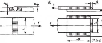
With this type of connection, it is welded over the entire length of the contact, therefore the length of the seam is equal to the length of the joints of the parts being welded, reduced by 2t, twice the thickness of the metal. The width of the seam depends on the shape of the edges and the thickness of the parts. Schemes of design options for butt joints are shown in the following figures.
Design diagrams for butt joints
If during welding work materials are used in accordance with Appendix 2 of SNiP II-23-81, no calculations are made, only visual quality control of the connections made is carried out.
Calculation of fillet weld geometry
Calculation of the geometric dimensions of fillet welds under the influence of a load passing along the axis of the center of gravity is carried out along the selected section, the most dangerous in this connection. This may be a calculation based on the cross-section of the weld metal or the fusion boundaries of materials. The figure below shows both sections.
Fillet weld geometry diagram
In this type of welded joints, stresses of various types act, but the dominant load is the shear force. Fillet welds are checked using the following formulas.
Calculation formula for weld metal
Formula for calculating the fusion boundary
where N is the maximum tensile or compressive force; βf and βz – tabular coefficients for steel; kf – weld leg length; lw – length; Rwf – design shear resistance; Rwz – the same but in the fusion zone; γс – tabular coefficient of operating conditions; γwf and γwz – the same, but for different operating conditions.
The main geometric characteristic of all fillet welds is the size of their leg, i.e. the thickness along the fusion boundaries. The size of the leg depends on the thickness of the parts, material and welding method. You can select the value of this geometric parameter in the table below.
Table of minimum fillet weld legs
For steel structures with maximum material flow characteristics above 590 N/sq.mm or a thickness of connected parts above 80 mm, the value of the minimum leg size should be taken in special specifications.
For structures of the fourth group, the size of the fillet weld leg should be reduced by 1 mm for parts with a thickness of no more than 40 mm and reduced by 2 mm for parts thicker than 40 mm.”
Tools for checking seam dimensions
A weld geometric parameters meter is a specialized tool that can be used to measure the main characteristics of these elements of welded structures. Among the variety of such measuring instruments, the following groups of products can be distinguished: templates, universal meters and devices specialized in measuring one parameter. A professional welder’s kit includes several such tools that allow you to measure both parts prepared for welding and the weld itself.
Consequences of incorrect leg calculations
We have already considered the negative consequences of a large leg. The second common mistake is that the seam leg is too small. Then there is little deposited metal on the sides, which reduces the strength of the connection. If it breaks or vibrates, the structure may not withstand the load and the seam will crack. Although the small leg saves consumables, it is only acceptable for non-essential connections (barbecue, table, etc.).
Another mistake welders make is an asymmetrical leg. Most often, the bottom flange of the seam is too wide, and the top flange is too short. This happens when the technique is incorrect or the welding mode is selected, because the molten metal flows down under the influence of gravity. The seam looks wide, but only slightly extends to the vertical side, so it holds weakly and is not designed for serious loads.
What GOST 16037-80 regulates
GOST 16037-80 was approved for use by the Decree of the USSR State Committee for Standards in the 1980s. It came into force in July 1981 and is still in force today. GOST replaced the previously existing standard in this industry 16037-70. In December 1990, the last and only changes were made to the document.
The scope of GOST regulation is welded joints of steel pipelines. It is required for use:
The mandatory nature of the standard means that all welders who begin welding steel pipes must take into account the provisions of the standard. Welded joints that are used for the production of pipes from strip and sheet material are excluded from the scope of regulation of the document.
When installing pipeline systems, one of the most common methods is manual welding, the production requirements for which are specified in GOST 16037-80. The full text of the document can be found here.
The safety of operation of pipeline systems largely depends on the quality of joints and seams.
With strict adherence to the requirements of the standard during the design and formation of the technological process and the actual execution of pipeline welds, the required level of quality is ensured.
Calculation of legs based on metal thickness
When choosing the length of the side of the triangle, the dimensions of the workpieces, position and type of joint are taken into account. The selection is carried out for each element, but general principles are taken into account. In the household, you can use a template to measure.
In order for the connection to be strong enough, both identical sides of the triangle must have the same length (if the elements are located at an angle of 90 o).
Connections can be:
- butt (without beveled edges, with one-sided, with V-shaped, X-shaped, curved bevel);
- end;
- overlap;
- corner (angle from 30°, one-sided, two-sided without beveled edges, with one or two bevels);
- T-shaped (acute or straight angle, one-sided, two-sided, without beveled edges, with one or two bevels).
Main types of welds and their brief characteristics
GOST describes three types of welded joints of steel pipelines and provides their symbols. This:
- Butt - “s”.
- Angular – “y”.
- Overlapping – “n”.
Within each type, the standard distinguishes various subtypes depending on different parameters. These include the diameter and thickness of the pipe being welded, the type of weld, the number of sides of the weld, the configuration for the gasket and the possibility of its removal, the presence of bevel of the edges (bevel of one or two edges), the shape of the cross-section of the edges or suture material, and the welding method.
According to GOST 16037-80, when connecting a pipeline, welding under shielding gas (argon), submerged arc and gas can be used. When working in an atmosphere of protective gases, the use of consumable and non-consumable electrodes is allowed.
To determine welding technological parameters, GOST 16037-80 recommends taking into account the following parameters (the document contains specific values depending on the type of welding):
- workpiece thickness (s);
- seam width (e);
- distance between edges (b);
- convexity (g);
- seam thickness (a);
- dulling of edge (c);
- overlap depth (B);
- fillet weld leg (K);
- pipe diameter (Dn);
- flange chamfer size (f).
All specified parameters are not relevant for all types of seams.
During the work, various types of welded joints are used depending on the specifics of the situation. For welding circular joints of pipes according to GOST, butt joints with the designation C1-C53 are used. This type of seams, in turn, can be made as one-sided or double-sided, straight and with rounded beveled edges.
Single-sided seams may include a removable or retained lining, as well as a fusible insert.
When connecting sectors at turns, the connections can be made with beveled edges and have the symbol C54-C55.
When connecting a flange to a pipeline, the designation C56 is used.
Fillet welds are prescribed in the standard as U5-U21, lap welds - H1-H4.
Square No. 4, welding methods
The standards also contain designations for welding methods; here are examples of the most common ones:
- A – automatic submerged without cushions and linings;
- Af – automatic submerged arc on a pad;
- ИH – in an inert gas with a tungsten electrode without additives;
- IHP – method in inert gas with a tungsten electrode, but with an additive;
- IP – method in inert gas with a consumable electrode;
- UP is the same thing, but in carbon dioxide.
In square No. 4 we have the welding designation UP - this is a method in carbon dioxide with a consumable electrode.
Cutting pipes for welding
GOST 16037-80 regulates not only the types of welded joints of steel pipelines (butt, lap and corner), but also the characteristics of preparatory measures taking into account the type.
Before carrying out welding work, it is necessary to carry out preparatory measures. These include:
- Mechanical cleaning of products . It is required to remove dust, traces of corrosion and oxide film.
- Chemical treatment to remove oil, grease and film stains.
- Edge cutting.
Cutting involves mechanical processing of the edge. During pipeline installation, cutting is carried out using special machines. When carrying out repairs, cutting using angle grinders is allowed.
Edge cutting must be performed when the thickness of the workpieces for welding is from 4 mm. For corner joints, bevel one or both edges at a 45-degree angle.
Joints on steel pipelines can be rotary or fixed. When welding a pipeline, it is recommended to use the first type, since they allow the welder to take the most advantageous lower position. The edges are cut along the entire perimeter.
With a butt connection, the difference between the wall thicknesses cannot be more than 10% and exceed 3 mm.
Before installation, the edges and heat-affected zone are also processed to 20-30 mm. It is cleaned of mechanical impurities, corrosion traces and oil and fat stains.
Before electric arc welding, the ends of the pipes must be tacked to each other. For pipe diameters not exceeding 300 mm, 4 tacks are made. If it exceeds 300 mm, then tacks are made evenly every 200-300 mm.
Welding of pipes with a thickness of more than 12 mm is carried out in three steps (penetrations).
If thick pipe blanks are connected, then the formed seam must be made thicker than the part itself. To form a connection with the specified parameters, you need to cut the edges after chamfering. At the same time, the electrode is provided with access for high-quality welding of the seam.
When calculating technological cutting parameters, special attention should be paid to the correctness of the calculation and compliance with certain cutting values. This reduces labor intensity, allows you to use materials economically and control costs.
When preparing joints, the type of chamfer depends on the thickness of the workpieces: with a thickness of 3-25 mm, a one-sided chamfer is used, with a thickness of 26-60 mm, a double-sided chamfer. For corner joints, the following boundaries are set: for values up to 20 mm - one-sided, up to 50 mm - two-sided.
Based on the geometric shape of the profile, the following subtypes of cutting are distinguished:
- Traditional (standard) bevel with a trapezoidal profile.
- X-shaped, when two bevels are made in such a way that the profile resembles the outline of the letter X (practice for using a workpiece with a thickness of 3-25mm).
- U-shaped, where the cross-sectional profile has a curved shape and resembles the letter U. GOST recommends using this form for large workpiece thicknesses (26-60mm) to reduce the cross-sectional area and reduce material costs.
If the pipe has a thickness of over 60 mm, then special shapes are used (in particular, ledges and complex curved profiles).
Gas cutters and mechanical processing are used for cutting. The first method has certain limitations and disadvantages: it has low qualities. The highest accuracy is ensured by milling; for large-diameter pipes, special trimming machines or grinders can be used.
Thus, GOSTs for welding activities are an important document that regulates the conditions for preparing and carrying out welding work. GOST 16037-80 defines methods for welding steel pipelines, types of connections, cutting methods and structural elements for each type. Compliance with the recommended parameters extends the service life of pipelines, ensures durability, strength and tightness of seams.
The meaning of the parts to be welded
The welded parts play an important role in obtaining a high-quality and durable connection. The main significance here is the heterogeneity of the thickness of the various structural elements to be combined and the roughness of the surfaces that are processed before welding.
This state standard reveals the following aspects that need to be taken into account when manufacturing the product:
- When making tees from steel pipes, you should use the seams and types of connections specified for branches with pipes, and in the case of assembling crosses, transitions with pipes, the corresponding assemblies of pipe with pipe or pipe with flange.
- If the thickness is different, but does not exceed the difference values (see Table 1), welding is allowed in the same way as for elements of the same thickness. Nevertheless, the dimensions of the seam and the types of edges must be selected according to the thickness of the larger part. To ensure a smooth transition from one element to another, the seam surface may be positioned at an angle.
- If the difference in the wall thickness of the pipes being connected exceeds the values given in Table 1, then the part with a greater thickness must be beveled so that it matches the thickness of the thinner part. The dimensions of the weld must be selected according to the part with a smaller thickness.
- The roughness of the surfaces to be processed is Rz up to 80 microns.
- Shims and couplings used when making a weld must be made of the same steel as the parts being welded. If the elements are made of carbon metal, then it is possible to make them from steel 20 or 10.
- When performing inspection using radiography, the gap between the pipe being welded and the remaining lining is determined - it should not be more than 0.2 mm. If the connection is not subject to radiographic testing, the gap does not exceed 0.5 mm. Local clearances of up to 0.5 mm and up to 1 mm, respectively, are allowed for the designated connections.
- When welding pipes, a meltable insert is used; the gap between it and the inner or side edge of the pipe should not exceed 0.5 mm.
Recommended reading: The difference between AC and DC welding
Table 1
| Thickness of thin part | Thickness difference |
| Until 3 | 1 |
| From 3 to 7 | 2 |
| From 7 to 10 | 3 |
| From 10 | 4 |
Careful preparation of parts before welding and establishing their compliance with the technical conditions of this GOST will make it possible to produce a welded joint of proper quality.
What GOST 16037-80 regulates
GOST 16037-80 was approved for use by the Decree of the USSR State Committee for Standards in the 1980s. It came into force in July 1981 and is still in force today. GOST replaced the previously existing standard in this industry 16037-70. In December 1990, the last and only changes were made to the document.
The scope of GOST regulation is welded joints of steel pipelines. It is required for use:
The mandatory nature of the standard means that all welders who begin welding steel pipes must take into account the provisions of the standard. Welded joints that are used for the production of pipes from strip and sheet material are excluded from the scope of regulation of the document.
When installing pipeline systems, one of the most common methods is manual welding, the production requirements for which are specified in GOST 16037-80. The full text of the document can be found here.
The safety of operation of pipeline systems largely depends on the quality of joints and seams.
With strict adherence to the requirements of the standard during the design and formation of the technological process and the actual execution of pipeline welds, the required level of quality is ensured.
Main types of welds and their brief characteristics
GOST describes three types of welded joints of steel pipelines and provides their symbols. This:
- Butt - “s”.
- Angular – “y”.
- Overlapping – “n”.
Within each type, the standard distinguishes various subtypes depending on different parameters. These include the diameter and thickness of the pipe being welded, the type of weld, the number of sides of the weld, the configuration for the gasket and the possibility of its removal, the presence of bevel of the edges (bevel of one or two edges), the shape of the cross-section of the edges or suture material, and the welding method.
According to GOST 16037-80, when connecting a pipeline, welding under shielding gas (argon), submerged arc and gas can be used. When working in an atmosphere of protective gases, the use of consumable and non-consumable electrodes is allowed.
To determine welding technological parameters, GOST 16037-80 recommends taking into account the following parameters (the document contains specific values depending on the type of welding):
- workpiece thickness (s);
- seam width (e);
- distance between edges (b);
- convexity (g);
- seam thickness (a);
- dulling of edge (c);
- overlap depth (B);
- fillet weld leg (K);
- pipe diameter (Dn);
- flange chamfer size (f).
All specified parameters are not relevant for all types of seams.
During the work, various types of welded joints are used depending on the specifics of the situation. For welding circular joints of pipes according to GOST, butt joints with the designation C1-C53 are used. This type of seams, in turn, can be made as one-sided or double-sided, straight and with rounded beveled edges.
Single-sided seams may include a removable or retained lining, as well as a fusible insert.
When connecting sectors at turns, the connections can be made with beveled edges and have the symbol C54-C55.
When connecting a flange to a pipeline, the designation C56 is used.
Fillet welds are prescribed in the standard as U5-U21, lap welds - H1-H4.
Types of welding seams
First, ESKD is the Unified System of Design Documentation, or, to put it simply, a set of various standards according to which all modern technical drawings, including documentation for welding work, must be carried out.
This system contains several standards that interest us:
- GOST 2.312-72 entitled “Conventional images and designations of seams of welded joints”.
- GOST 5264-80 “Manual arc welding. Welded joints”, which comprehensively describes all possible types and designations of welds.
- GOST 14771-76 “Seams of welded joints, welding in shielding gases.”
To understand the symbols of welding methods in engineering drawings, you need to understand their types. We suggest looking at an example of a weld designation in the drawing:
It looks bulky and intimidating. But we won’t be nervous and will slowly figure it out. There is a clear logic in this long abbreviation, let's start moving step by step. Let's break this monster down into nine parts:
Now these same components in squares:
- Square 1 – auxiliary signs to indicate: a closed line or an installation connection.
- Square 2 is the standard by which the symbols are given.
- Square 3 – designation by letter and number of the type of connection with its structural elements.
- Square 4 – welding method according to the standard.
- Square 5 – type and dimensions of structural elements according to the standard.
- Square 6 – characteristic in the form of the length of a continuous section.
- Square 7 – characteristics of the connection, auxiliary sign.
- Square 8 is an auxiliary sign for describing a connection or its elements.