Home \ Catalog \ Turning tools with carbide inserts
The main type of metal-cutting tool for forming the geometric shape of a part, including the internal surfaces of shaped parts, cutting threads and chamfering are turning cutters. All turning cutters, regardless of their type (cutting or through cutters, threading cutters or grooving radius cutters, boring cutters for through/blind holes or planing cutters), as well as the design of the cutting part (cutters made of high-speed steel, with carbide inserts, self-cutters) Can be used on various types of lathes.
Design
Absolutely all options, from the most common to the very specific, consist of the following two key parts:
- a holder with a strictly defined cross-section, the shape of which is either rectangular or square, for reliable fixation in the equipment;
- a head with several usable planes and edges (each of which will be discussed below) - for direct processing of the material (be it alloy steel, cast iron or some other).
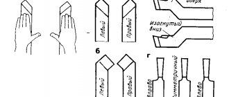
According to geometry, the following execution methods are distinguished:
- straight - both of its above-mentioned components are located either parallel or on the same axis;
- curved - with a slightly noticeable curvature of the profile inward;
- bent - with an obvious bend reaching an almost zigzag shape;
- retracted - the head is narrower in width than the holder and is placed either symmetrically along the axis or offset, to the right or left.
Also, absolutely all types of cutters for lathes that are relevant today can boast of a certain surface geometry, the relative arrangement of which we now move on to.
Planes
There are three:
- The main one is parallel to the reference and, accordingly, to the tool feed vector, which can be located both longitudinally and transversely.
- The cutting plane is perpendicular to the previous one, includes the main edge, and runs tangentially to the workpiece.
- Main secant – passes through the main edge, perpendicular in its role to the projection.
Add here an auxiliary one, which is a secant and is located at an angle of 90 degrees to the corresponding face.
It is important that the dimensions remain within the standard range, that is, do not exceed 160X100 - 630x1000 for rectangular tools and 40X40 - 400X40 for square ones.
Cutter angles
Their parameters depend on the type and conditions of use of the element we are considering, as well as on the hardness of its material and the characteristics of the workpieces being processed. The latter, in turn, determine the sharpness of the head, which means they can be:
- The main ones (according to the placement of planes):
- the front one specifies the degree of deformation upon impact, the efficiency of heat removal, and the applied force; should decrease with increasing hardness of the surface of the part;
- rear - affects the friction force, wear rate, and the quality of the final technological operation.
- sharpening – determines the strength of the equipment;
- cutting – determines the depth of penetration.
- main – sets the quantity and volume of chips to be removed;
- secondary - directly affects the degree of roughness, which decreases proportionally as it decreases.
This is interesting: Chrome plating of plastic at home: technology and tips
Tool design and geometry
A classic groove cutter consists of two tool parts - a working head-cutter and a fixing rod, with which the spare part is secured in the machine holder. The holder rod is made of high-alloy steel, which provides high strength and protection of the tool, and also minimizes the risk of corrosion and deformation. The cutting part of the KR is made in the form of a rectangular or oval plate, which is also made of high-alloy steel.
The plate is usually made of metal that contains additives based on cobalt, manganese or tungsten - this provides the tool with high strength, so it dulls slowly. On some CDs, the head is made in the form of a replaceable head, which is also made of steel with a high content of cobalt, manganese, tungsten and similar alloying additives. Tool sharpening should be done on a sharpening machine, and it is recommended to entrust this work to an experienced worker.
A few words about the correct sharpening of groove cutters:
- During sharpening and assembly of the part, it is necessary to obtain a rake angle ranging from 15 to 25 degrees. The location of the cutter affects how the workpiece will be processed in the future while the cutting machine is running.
- The working edge should be sharpened evenly along its entire length. If you ignore this rule, then strong vibration will occur during operation of the machine, which will make cutting inaccurate. Due to vibration, the tool also heats up additionally, which will reduce the strength of the tool and make sharpening more difficult.
- Select the optimal geometry experimentally. GOST standards do not provide precise instructions regarding the sharpening of this tool due to the fact that surface treatment has specific features. Therefore, it is not possible to select a universal angle of inclination and quality of sharpening.
To optimize sharpening, it is recommended to perform it in several stages. First, you need to make several test grooves to determine the optimal sharpening parameters. Once the worker has mastered his hand, he can begin the main sharpening. Only experienced turners with experience who are fluent in their craft and know all the intricacies of working with groove cutters can skip the test groove.
What is a metal lathe cutter?
This tool is a product whose elements carry out turning of metal workpieces on metalworking equipment. The cutter design contains:
- Holder. This element is necessary to fix the product. The cross section can be square or rectangular.
- Working head. It processes a metal workpiece on a machine. The shape of this cutting element is made from several planes. The work is performed by cutting edges sharpened at a certain angle. Sharpening cutters for a metal lathe depends on the characteristics of the workpiece material and what type of processing is being performed.
Geometric parameters and tool dimensions
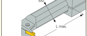
The design of any groove cutter is characterized by its geometric parameters.
- Geometry of the body or holder: L – length of the body, B and H – dimensions of the cross-sectional sides.
- Location of the cutting element in the body. The socket for the plate can occupy the entire width of the case or one of the corners. In the latter case, the width of the socket is indicated by the letter n. The plate can be placed in the socket at a certain angle to the body.
Shape of the working cutting plate: l – length of the working part of the cutter, b – height of the plate body, S – thickness.
The blade for cutting the workpiece also has its own parameters, expressed in angles.
- “Gamma” displays the front sharpening angle - this is the main element of the cutting edge.
- “Alpha” is the rear main sharpening angle.
- “Alpha” with index 1 is the rear corner for auxiliary purposes.
- "Lambda" is the angle at which the cutting edge is inclined.
- “Phi” is the main purpose angle located in plan.
- “Phi” with index 1 is an auxiliary angle located in plan.
Parting and Grooving Tool Models in SolidWorks
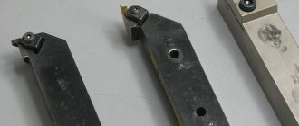
As mentioned in earlier articles, 3D models of a cutting tool can, of course, be built from scratch in SolidWorks. But I think there is no point in this since the tool manufacturers have already done this for us.
We go to the website, and for example, download two models of cutters under the designations: “RAG123H10-32B” , “RF123H13-2525BM” .
Sandvik coromant website
And in the search line, enter these designations one by one and download the cutters by clicking on “Download” in the “download detailed 3D model” line.
Downloading a 3D model of the tool from the Sandvik coromant website
Next, open the downloaded files and get 3D models of these cutters in SolidWorks.
Internal grooving cutter RAG123H10-32B
Parting and grooving cutter RF123H13-2525BM
As you can see, this is much easier and faster than creating a cutter in SolidWorks from scratch.
If anyone needs this model, you can download it at the end of the article!
Main dimensions and materials
A turning groove cutter is generally no longer than 270 mm, the width of the working head varies from 2 to 10 mm, the thickness and height in the case of a rectangular and square section of the rod reaches 50 mm. When working on machines at low speeds, carbon tool steel is used to make cutters, alloyed to speed up operations. At high speeds, high-alloy steel can be used, the speed increases up to one and a half times, the tool can withstand increased temperatures.
Inserts for turning grooves in compound cutters can be made of various materials:
- carbide brazed;
- metal-ceramic based on compounds of cobalt with titanium and tungsten;
- mineral-ceramic, used mainly for processing high-strength parts, resistant to high temperatures, but fragile and expensive;
- diamond, very durable, but burn out at high temperatures;
- CBN, based on boron nitride, maintains temperature well and can process high-strength materials.
Each of the above materials is characterized by application features; when choosing, price is not the main argument - you can buy many cheap ones that cannot replace several expensive ones, but with optimal parameters. Turning groove cutters are an expensive tool; choosing them correctly will save money and will not disrupt the production cycle.
Categories of cutters
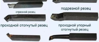
Of all the available parameters by which cutters are classified, the main one is the type of workpiece processing. Depending on their technological purpose, replacement cutters for a metal lathe are:
- Passable. Using this product, the turner processes cylindrical and conical outer surfaces of metal workpieces. Processing is carried out along the axis of rotation of the workpiece.
- Cut off. Used for cutting workpieces and trimming them.
- Shaped. Using this cutter for a metal lathe, you can grind shaped surfaces of workpieces. The tool is also used to form shaped ridges and grooves.
- Boring. The product is used for boring both through and blind holes. Boring cutters can be persistent or through.
- Slotted or grooved. Internal and external grooves in cylindrical metal workpieces are machined with these cutters. Also, this type of cutters is used in cases where it is necessary to cut the workpiece at a right angle.
- Threaded. They are used in cases where it is necessary to equip the workpiece with internal or external threads.
- Galtelnymi. Using cutters of this category, the turner can process the transition surfaces of workpieces.
- Chamfered. These cutters are used for chamfering.
This is interesting: Metal laser cutting technology - equipment, features, video
Types of groove cutters
Turning tools for forming grooves include cutters for internal and external machining. Both the first and second can be made entirely of carbide materials or have a replaceable cutting part. Carbide cutters are a fairly expensive tool, so their use must be economically feasible. When performing external work, products with replaceable inserts are usually used; using carbide groove cutters in such cases does not make sense.
The situation is completely different with the processing of internal grooves. Here it is necessary to take into account the diameter of the hole into which the cutter is to be inserted, as well as the rigidity of the tool. The requirements for a cutter to have a minimum size of its holder and sufficient rigidity to perform metal processing are met only by carbide groove tools.
Naturally, when the processing conditions and geometric parameters of the workpiece allow it, it is more advisable to use an inexpensive tool with replaceable inserts to form external and internal grooves.
Selection of cutters for lathes.
The selection of turning cutters for a specific metalworking operation should be approached comprehensively, assessing the shape of the part, the toughness and hardness of the metal or alloy being processed, the permissible error of deviations from the established dimensions and the required surface roughness. It should be taken into account that in addition to the material of the part, the cutting part and the cutter holder, the quality of processing will be influenced by:
- cutter feed speed and depth of cut;
- cutting edge angle and main relief angle (between the rear plane of the cutting part and the plane of the processing surface);
- chip breaking method and vibration resistance of both the holder and the cutting head;
- the shape of the socket in which the carbide plates are installed and the method of fastening the holder itself.
Damn.1
Damn.1
Table 1
Dimensions, mm
| Cutter section | |
| 4x4 | 4 |
| 6x6 | |
| 8x8 | 6 |
| 10x10 | 8 |
| 12x12 | 10 |
| 16x16 | 12 |
2. Structural elements and geometric parameters of cutting tools are indicated in Figure 2 and Table 2.
Damn.2
Damn.2
table 2
Dimensions, mm
| Cutter section | Largest cut diameter | ||
| 6x6 | 1,5 | 10 | |
| 8x8 | 5 | 2,0 | 12 |
| 10x10 | |||
| 12x12 | 8 | 16 | |
| 16x10 | 3,0 | 30 | |
| 20x12 | 12 | ||
| 4,0 | 35 | ||
| 25x16 | 14 | 3,0 | 30 |
| 5,0 | 50 | ||
| 32x20 | 18 | 4,0 | 35 |
| 6,0 | 60 | ||
| 20x12 | 12 | 4,0 | 35 |
| 25x16 | 14 | 5,0 | 50 |
| 32x20 | 18 | 4,0 | 35 |
| 6,0 | 60 |
The text of the document is verified according to: official publication Reztsy. Design and dimensions. Part 1: Sat. GOST. - M.: IPK Publishing House of Standards, 2003
Incisor directions
Depending on the direction in which the tool begins to move, cutters are divided into two types:
- Left type. The start of processing starts from left to right. You can determine this type by placing your left hand on the product. The bent thumb will be located on the side of the cutting edge of the incisor.
- Right type. The serve is performed from right to left. To determine this type of cutter, you should place your right hand on it. Your thumb will be on the cutting edge side of the tool.
Selection rules
With the correct selection and well-developed technological cycle, the grooving cutter can work for a long time without sharpening. Main factors influencing the choice:
- the cutting edge must be suitable for processing the material (stainless steel should not be processed with carbon tool steel);
- you should take into account the features of the machine (wear, speed, specific capabilities);
- temperature conditions of the operations performed (as the temperature rises, the cutting quality decreases, diamond pads simply burn out at high temperatures);
- calculation of the optimal feed speed of the tool and, accordingly, the cut (when calculating the cycle, it may be necessary to carry out test grooves for a correct assessment);
- possibility of sharpening (compound cutters with a set of cutting plates are unrivaled, they can be sharpened to the stop);
- specifics of the product (shaped surface, shape of grooves, requirements for tolerances and cleanliness of processing).
For example, it is necessary to machine a stepped shaft and cut cavities of a given diameter at the ends. The workpiece is made of alloy steel, the wear of the machine is high and it is not possible to work at high speeds.
It is optimal to choose three tools for this situation:
- for rough machining of the outer surface, you can use a tool made of high-alloy steel; the operation is performed at low speeds with a feed of about 0.1 mm/rev;
- for finishing machining, a turning cutter made of R6M5 steel, corresponding to GOST 18874-73, is well suited; the tool material is high-speed steel, holds temperatures up to 600 degrees;
- The internal cavity should be selected using a boring tool for finishing with a working surface made of hard alloys.
Groove cutter - requirements according to GOST
The technical characteristics of the CD are specified by GOST standards, which were adopted back in the USSR. The main standard is the document GOST 2209-82, as well as its revision from 1990. A number of other regulatory documents are also in force - GOST 18874-73, GOST 18885-73, SNiP standards and others. They stipulate the main parameters of groove cutters - geometry, wear resistance, strength, marking, cutting quality, testing methods. When choosing a CD, you need to remember the following:
- Most of the cutters on the market are of Russian, Chinese or European origin. Russian products have good technical characteristics, a long shelf life, and do not require additional requirements for transportation or storage. Another plus is the reasonable price. However, they are recommended for processing ordinary parts at low temperatures.
- If you want to process a durable and/or heated surface, then preference should be given to spare parts from European manufacturers. They cost more, but their technical parameters are better. In addition, they dull more slowly, are easily stored, and withstand exposure to water and chemicals longer.
- With Chinese parts the situation is much more complicated. Many Chinese manufacturers make quite high-quality spare parts that are not inferior to Russian and even European analogues. And they are very cheap. However, there are still a lot of Chinese low-quality cutters on sale, so you need to choose parts carefully. It makes sense to purchase Chinese products in small quantities (in case of bad incisors, you will not lose much money).
Features of turning using a groove cutter
The cutting modes when using groove-type cutters have some differences from the modes of processing the workpiece with other types of turning tools. Thus, the depth of cut is taken to be a value equal to the width of the groove being formed, and the tool feed per revolution of the part is measured in the direction perpendicular to its axis. The feed rate, depending on the material from which the cutting part of the groove tool is made, is selected in the range of 0.07–0.2 mm/rev, and the cutting speed is 15–180 m/min.
Several types of grooves can be obtained on the surface of the workpiece.
- Narrow grooves, the width of which corresponds to the width of the cutting part of the tool, are made in one pass of the cutter, which is fed manually. Before this, the exact location of the groove is determined on the surface of the part, and then the cutter is placed opposite this place and fed.
- The grooves on the ledges and ends of the part are made according to the same principle; their diameter is set using the transverse feed dial, and their depth is set using the longitudinal movement dial of the caliper.
- Wide grooves are made in several passes according to the following scheme. First, determine the location of the right edge of the groove and place the cutter opposite this location. Using a transverse feed, the cutter is cut into the part to a depth that is 0.5 mm less than the depth of the groove being cut (this allowance is left for finishing). Then, using a longitudinal feed, the groove tool begins to move to the left edge of the groove being cut, the boundary of which has been previously marked. After the rough groove is formed, its bottom is processed cleanly - to the required depth, carrying out the longitudinal feed of the cutter from left to right. In the event that it is necessary to form a groove with a very precise location of its left and right edges, allowances can also be left on them during roughing, which are then removed using the transverse feed of a groove or scoring cutter.
Types of work performed by grooving cutters
Recommendations for selecting groove cutters
When choosing a groove cutter, you should be guided by the following considerations:
- First of all, they analyze the drawing according to which the part will be manufactured. The drawing shows all the parameters of the grooves: width, depth, shape, as well as standards for manufacturing accuracy and possible tolerances.
- The metal from which the part is made. For carbide metals, appropriate cutters with a carbide blade are used; for soft metals, ordinary grooved ones are used.
- When choosing a tool for cutting grooves inside a hole, the diameter of the holder and the size of the protruding edge of the knife are important. Here, too, it is more advisable to use carbide equipment.
- Equipment for carrying out operations. The choice of groove cutter is determined in this case depending on the possible operating modes of the machine, the configuration and type of tool holder.
- Features of the technological process. The technical process can affect the processing speed of the product. The higher the speed, the stronger and more durable the grooving equipment must be used to achieve processing goals.
- Is there any provision for lubrication of the treatment area during the operation? Lubrication has a positive effect on the work, removing part of the load from the groove tool and thereby making it possible to use simpler equipment.
State standards
The technical regulations adopted in the USSR for metal-cutting tools remain relevant today. For groove cutters with carbide brazed inserts, the parameters and geometry are determined by GOST 2209-82 or its later version GOST 2209-90. They provide comprehensive information on geometry, wear resistance and methods for checking the quality of the material.
Download GOST 2209-90
Lathe cutters must comply with GOST 18874-73.
Download GOST 18874-73
It describes the design features, dimensions and geometry of high-speed steel tools, and their markings. The regulation is almost half a century old, and it is actively exploited, which indicates the active use of obsolete and worn-out machine tools in most industries. The latest changes were made to GOST 18874-73 in 1985, during which time technologies and materials for cutters have changed dramatically. Tools for external grooves comply with GOST 18885-73, the situation is similar to that described above, modern groove cutters can differ radically from the standard, providing better quality and speed of cutting.
Download GOST 18885-73
In general, standards that are half a century old cannot be effective. During this time, technology has changed significantly, but updating the machine fleet is extremely expensive, so cutters according to old GOST standards will be in demand and needed for a long time. Modern production with high-tech equipment relies on other criteria for selecting tools for metal turning.
GOST 18885-73 and 18874-73 regarding groove cutters
The contents of GOST 18874-73 “Slotting and parting cutters made of high-speed steel” and GOST 18885-73 “Threaded turning cutters with hard alloy plates” can be found below:
GOST 18874-7
GOST 18885-73