11/14/2019 Author: VT-METALL
Issues discussed in the material:
- What are the types of defects in metal products?
- How can you detect defects in metal products?
- What are the defects of metal products during casting?
- What defects are caused by plastic deformation?
The production of metal objects is a complex technological cycle. Some operations can be either excluded from this chain or repeated. During processing, the metal undergoes changes and flaws may appear on it. Next, you will learn what types of defects there are in metal products, as well as how they can be identified.
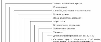
Types of defects in metal products
Due to defects, the physical and mechanical properties of metals, such as electrical conductivity, magnetic permeability, strength, density, and ductility, deteriorate. It is customary to identify defects of a fine structure or atomic scale, namely dislocations, vacancies, etc., and more coarse ones. The latter include submicroscopic cracks that appear at the boundaries of crystal blocks and on its surface.
Micro- and macroscopic defects of metal products, suggesting a violation of continuity or homogeneity, are considered even more serious. They appear for two reasons: due to the imperfection of the technology used and the low manufacturability of multicomponent alloys. The fact is that when working with such alloys, it is necessary to especially strictly observe the regimes established for all stages of manufacturing and processing.
From the point of view of applied, technical understanding, defects are deviations from the established norm, in which the performance characteristics of a metal or metal product deteriorate, a reduction in grade or rejection of products occurs. But you need to understand that not every metal flaw applies to the product. If deviations do not affect the performance of the metal part, they are not perceived as defects.
Deviations recognized as defects for products operated under certain conditions (for example, under fatigue loading) may not be taken into account under other operating conditions (for example, under static loading).
Amounts of permissible wear of parts of units
| Group number | Defect or damage | Sketch | Category | Maximum permissible values of parameters in technical condition | Note | |
| In good working order | Efficient | |||||
| 1 | Cutout in a structural element | A | Not allowed | Checked by calculation | — | |
| 2 | Cutout in a structural element | B | Same | Same | — | |
| 3 | Missing element | · | A | Same | Not allowed | — |
| 4 | Rupture (fracture) of an element | A | Same | Same | — | |
| 5 | Burning a hole in a structural element | B | Same | Checked by calculation | — | |
| 6 | Collapsing and vertical wear of the rail head | IN | Not allowed | d ≤ 6 mm | For KR70 and P43 | |
| d ≤ 7 mm | KR80 and P50 | |||||
| d ≤ 10 mm | KR100 | |||||
| d ≤ 12 mm | KR120 | |||||
Figure 16 - Allowable wear
Limit values for wear of parts
The amount of wear that does not interfere with the normal operation of the connection is called acceptable.
Wear, at which further operation of a unit or machine is technically unreliable or economically unfeasible, is called marginal.
Changes in the size of parts and their wear can occur in different ways. As a rule, one of the rubbing surfaces wears less evenly than the other; for example, bearing shells wear less evenly than shaft journals. The teeth of sprockets and gears, excavator bucket teeth, engine crankshaft journals and other parts are subject to uneven wear. As a result. wear, the strength of the parts decreases, the nature of the fit changes, and the operation of other mating parts or the assembly becomes disrupted. Obviously, the moment of rejection of parts must correspond to the degree of wear that is maximum permissible for them.
Most often, the wear limits of parts are determined based on the following criteria:
- a decrease in the strength of a part when its dimensions change due to wear. Based on this criterion, in particular, the maximum wear of gear teeth is established;
- changing the service properties of a part or assembly. For example, when the piston rings wear out in an internal combustion engine, there will be an increased breakthrough of gases into the crankcase, oil consumption will increase, which means the service properties of the piston rings are lost and they need to be replaced;
- a change in the mating fit caused by an increase in the gap or a breakdown of the fixed connection due to a decrease in interference due to metal collapse;
- the influence of worn parts on the normal operation of other parts of the assembly. For example, misalignment of the shafts, which occurs when the bearings of the gear reducer are worn out, disrupts the correct engagement of the gears, which in turn causes their abnormal wear and sometimes breakage;
- reducing the wear resistance of parts. For example, if the wear of the shaft journal surface exceeds the thickness of the cemented layer, its operation must be stopped, since after this the wear rate increases several times.
The wear limit values can be established according to the technical conditions for the control and sorting of parts for their repair. For many construction machines, such standards have not yet been developed, therefore, when establishing wear limits, the following signs of loss of machine performance are used: a change in the nature of the fit between mating parts, the appearance of additional loads in the machine mechanisms that create the possibility of breakdowns, changes in the quality of the resulting product and productivity, difficulty starting the machine and other indicators.
Casting defects in metal products
Today in metallurgy it is customary to use several classifications of defects obtained during casting.
Defects are divided into types based on location. So, if a defect is detected inside a site, it is considered internal. If the problem appears during further processing, it is classified as an external defect.
VT-metall offers services:
From the point of view of external manifestations, the following main types of casting defects are distinguished: burn-in, in which a layer of molding materials sintered with the metal is firmly attached to the surface of the workpiece, and tides, which represent an upward deviation of the dimensions of the castings from the design.
Tides are divided into:
- Bays that form along the junction of parts of the form. The reason for their appearance lies in non-compliance with the dimensions of the models and poor connection of the elements of the flasks.
- Puffiness (thrust) - occurs due to the pressure of the melt on the loose mixture.
- A build-up that occurs when the flow of melt erodes a mold during pouring.
- Notches (ridges, burrs) formed when the melt flows into damage to the mold or rod.
Often, defects during casting appear in the form of surface defects. These include:
- Blockages. Masses of earth grains or slag. This problem appears due to errors made when designing molds, ill-conceived placement of gates, and failure to comply with storage and transportation technology.
- Uzhiminy - are formed during wet molding, when the layer of earth is torn at the point of liquid condensation and the melt fills the resulting void.
- Joints, or non-stilines, occur when contact occurs between layers of cooled melt. Since the required temperature is not reached, the threads cannot fuse properly.
- Films - appear when alloying additives oxidize.
- Wrinkling or folding. This defect looks like multidirectional folds on the surface of a metal product. This flaw is associated with the accumulation of a large volume of carbon in the metal.
- Effusion provokes an explosive release of graphite accumulations, so it looks like many burst bubbles.
- Kinglets also appear due to splashing of the melt during pouring. In this case, the metal ball crystallizes separately from the casting, without connecting with it.
- Warping of the casting occurs due to internal stresses provoked by uneven cooling.
Crystallization
Crystallization is a process involving the formation of crystals. This occurs when a metal changes from a liquid to a solid state. This is exactly what happens when welding metal products.
This process in the weld leads to deformation of the metals and the formation of cracks. What types of cracks form during crystallization of a weld? Hot ones, which have the second name crystallization, can appear in a metal weld at the last stage of crystallization. In this case, the temperature is close to solidus, when the last drops of liquid metal disappear.
Plastic defects in metal products
When rejecting workpieces, quite often one has to deal with inclusions of foreign metallic or non-metallic bodies, and the latter come in different sizes and shapes.
A tear is a local non-through rupture located across or at an angle to the direction of processing of the material. Such defects are formed due to the disclosure of internal discontinuities in the material, as well as non-compliance with the standards established for the processing process.
A through gap differs from the previous type in that through discontinuities are observed on the metal product. They are formed when a flat workpiece with uneven thickness is deformed, or the cause of a through rupture can be rolled-in foreign bodies.
The puncture looks like non-through single or group point depressions. They appear when contaminated cutting fluids are used or small metal and foreign elements come into contact with the workpiece. Another reason for pinching can be protrusions and stuck particles on the rollers.
We recommend articles on metalworking
- Steel grades: classification and interpretation
- Aluminum grades and areas of their application
- Defects in metal products: causes and search methods
Dents are individual single depressions of various sizes, shapes, and having flat edges. Dents appear due to damage to the metal during production, transportation, and storage.
A nick is an irregularly shaped depression. Typically, such a defect has sharp edges, as it appears when a metal product is hit.
Imprint – periodically repeating depressions, protrusions located throughout the metal product or in some of its areas. Imprints appear under the influence of irregularities on the rolling and straightening rolls.
The seizure looks like a wide longitudinal depression with an uneven bottom and edges. The reason for its appearance is the sharp friction of the workpiece against the part of the equipment with which processing is carried out.
A notch is a longitudinal narrow depression, the bottom of which can be rounded or flat. Formed when a metal product blank is scratched by protrusions on the surface of the equipment.
A scratch is an irregularly shaped depression with a random direction. Appears due to mechanical damage, for example, during storage or transportation of metal products.
Abrasion is a loss of shine on a particular area of a metal product, as well as an accumulation of small multidirectional scratches. Such defects appear due to friction between metal products.
Adhesion occurs as a result of particles or a layer of metal from a tool sticking to a metal product.
Sunset is formed due to the pressing into the product of particles of the metal being processed, burrs, protrusions and other defects that appear during the processing process.
Burnout manifests itself in the form of dark, melted or oxidized spots on a metal product, which are formed if the temperature and heating time of the material have been exceeded.
Methods for detecting defects in metal products
There are several levels of examination that are used for different depths and sizes of defects:
- Submicroscopic examination.
- Microanalysis.
- Macroanalysis.
Defects in the crystalline structure of metals are usually understood as deviations from the structure of an ideal, that is, defect-free, crystal.
Crystal structure defects are divided into types according to their shape and size:
- Dislocations, that is, the absence of a half-plane of the crystal lattice.
- Vacancies or voids in the nodes of the crystal lattice.
- Interstitial atoms, which imply the presence of additional atoms in the lattice between the nodes.
- Substitution atoms, that is, atoms of another element located in the nodes of the crystal lattice of the metal being processed.
1. Submicroscopic examination.
Its purpose is to identify defects at crystal or grain boundaries. The fact is that due to uneven crystallization or insufficient nutrition of the nuclei with a liquid solution, thin layers appear between the blocks of crystals. Or the reason may be hidden in the release of insoluble compounds and elements on the surface of the crystals of the solid phase. Thus, phosphorus and a number of refractory metals are not able to form compounds with iron in steels, so they are deposited at the grain boundaries.
Submicroscopic defects include chips in steel 38Kh2MYuA. The reason for their appearance is simple: during alloying of steel with aluminum, local planes are identified along the grain boundaries, which become the weak point of the metal during further processing.
2. Microanalysis.
In such a study, microscopes with a magnification of more than 100 times are used to identify defects. It is microanalysis that is most often used when searching for casting defects. This method allows you to determine the grain score, the presence and number of inclusions of non-metallic nature, copper, sulfur and phosphorus, and the structure of the metal.
The proportion of carbon and alloying elements contained in the steel determines which solid phases will be released during crystallization. Note that these stages have different strength, hardness and ductility. In corrosion-resistant steel grades, austenite, martensite or ledoburite phases are formed at different cooling temperatures.
Also, the key characteristics that determine the quality of the metal include the grain grade. The fact is that when this indicator decreases, the ductility of the metal increases, but its strength decreases. However, alloying with carbide formers or refractory materials makes it possible to strengthen the steel while maintaining its original ductility.
Prevention of cracks
There are certain measures that reduce the likelihood of various types of cracks:
- Reducing the rigidity of the connection of welded parts.
- Select the width of the weld commensurate with the thickness of the parts.
- The value of the welding current must correspond to the recommended type of connection. Exceeding will result in overheating.
- Select welding wire with low sulfur and carbon content.
- Observe the angle of inclination of the electrode.
- The seam should not be too narrow.
- Application of a multi-pass welding method. Single pass seams are less durable.
It would be a good idea to preheat the parts to be welded.