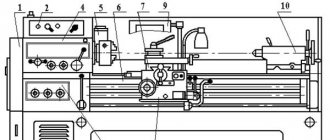
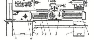
Kinematic diagram of a screw-cutting lathe 1K62
Kinematic diagram of a screw-cutting lathe 1k62
Legend
Mf6 - overrunning clutch to turn off the feed chain from the M2 electric motor when the caliper moves quickly;
Mf7 - safety clutch that slips when the feed mechanism is overloaded;
Mf8, Mf9 - clutches for turning on the caliper feed to the left or right;
z - number of teeth of the stepped cone (block B10, z = 26, 28, 32, 36, 40, 44, 48), with ring gear z = 36;
u2 is the transmission ratio from shaft XII to shaft XIV, which is switched by blocks B11 and B12;
B1..B - gear blocks;
a/b·c/d — replaceable guitar gears (tilt);
P - thread pitch in mm.
Screw-cutting kinematic chain of a screw-cutting lathe 1k62
When cutting all types of threads on a machine, the longitudinal movement of the caliper is carried out by the XV lead screw. To do this, the Mf5 clutch is engaged, and the z=10 gear is disengaged from the gear rack. The caliper is fed when the lead screw nut XV is turned on.
Metric thread cutting
Setting up the feed mechanism for cutting this thread is done by installing the B8 and B9 guitar blocks so that the transmission is carried out through wheels with a gear ratio uVIII-IX = (42/95)·(95/50) by turning on the Mf2, Mf3 and Mf5 couplings. Block B10 becomes the leader in this case.
The balance equation for a screw-cutting chain will be written as follows:
By substituting seven values of z (26, 28, 32, 36, 40, 44, 48) and four values of u2 (1/8; 1/4; 1/2; 1), one can obtain 28 thread pitch values ranging from P = 26/4 · 1/8 = 0.8125 to P28 = 48/4 = 12 mm. Of the 28, only 19 pitch values coincide with the metric threads used.
Modular thread cutting
Setting up the feed mechanism for cutting modular threads is done in the same way as for cutting metric threads, only the B8 and B9 guitar blocks are installed so that the transmission is carried out through wheels with a gear ratio u'VIII-IX = (64/95) · (95/97) , while the resulting thread pitch changes by a number of times equal to (64/95 · 95/97): (42/95 · 95/50) = 64/97 · 50/42 = 3200 / 4074 = 0.78552. Therefore, the resulting modular thread pitch is P' = 0.78552 zu2/4, and the module m = P/ /π = 0.78552 / 3.14 zu2/4 = 1/4 zu2/4.
Inch thread cutting
Setting up the feed mechanism for cutting these threads is done in the same way as for metric ones, but in this case only the Mf5 coupling is turned on, and all the others are turned off. As a result of this, the B10 gear block becomes driven.
The balance equation of the kinematic chain in this case will be written as follows:
Inch threads are characterized not by pitch, but by the number of threads K per inch of thread length. The number of threads is found from the formula:
Substituting seven z values and four u2 values into the formula, we get 28 different values of K, of which 20 are standard values.
Pitch thread cutting
When cutting pitch threads, the same kinematic chain is used as when cutting inch threads, only instead of 42/95 · 95/50 wheels, replaceable gear wheels 64/95 · 95/97 are installed on the guitar. In this case, the resulting thread pitch changes by a factor of 0.78552 and is equal to P = 0.78552 16 25.4 (u2/z), and K = z/0.78552 16.
It is known that between the pitch Dp and the number of threads K per inch there is a relationship Dp = Kπ. Therefore Dp = Кπ = πz / 0.78552 · 16u2 = 4z/16u2 = z/4u2.
Long pitch thread cutting
All kinematic chains written earlier related to threads with normal pitch.
To obtain an increased thread pitch, gear z=46 of block B6 is engaged with gear z=45 of shaft III. In this case, transmission from shaft VI to shaft VII is carried out through shafts V, IV and III with the following gear ratios:
a) at a spindle speed in the range n = 12.5..40 rpm (u search = 1/16)
b) at spindle speed in the range n = 50..160 rpm (u search = 1/4)
As a result, the resulting pitch of metric and modular threads increases by 8 or 32 times, and the number of threads per inch and pitch decreases by the same number of times.
When cutting threads with an increased pitch, a higher spindle speed than 160 rpm is not used.
Cutting precision threads
When cutting these threads, couplings Mf2, Mf4, Mf5 are activated. In this case, the transmission is carried out from the spindle through the replaceable guitar gears uVIII-IX = a/b·c/d to the IX shaft and then directly to the XV lead screw.
The balance equation of the screw-cutting kinematic chain in this case will be written as follows:
From the equation we obtain formulas for selecting the numbers of teeth of replacement guitar wheels:
for metric thread: a/b c/d = P/12;
for modular thread Р=πт we get a/b·c/d = πт/12 = 11m/42;
for inch thread P=25.4/K we get a/b c/d = 25.4/12K = 127/60K;
for pitch thread P=25.4π/Dp we obtain a/b·c/d = 25.4π/12Dp = 127·11 / 30·7Dp.
A set of replacement gears needed for cutting precise threads is supplied to the 1K62 machine upon special order.
Purpose of the machine
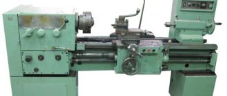
IZH 1I611P refers to professional equipment. Although it was produced in the middle of the last century, many enterprises still successfully use this technique. With its help, metal work is carried out:
- milling,
- turning,
- grinding.
Actions are performed not only in centers, but also on cartridges. The latter can be collet or cam - there is no fundamental difference.
It is also possible to grind inside objects using a tool that is mounted in a chuck. The screw cutting machine copes with products of various shapes. It is used to work with conical and cylindrical options. The thread is cut modular, metric or inch - depending on the required characteristics. Peculiarities:
- the rigidity of the thread head is determined by fixation based on the principle of no gap,
- the gearbox is convenient, since the gears for making threads do not change,
- coolant increases the service life of equipment,
- there is a professional chip removal system,
- it is possible to select in the previous step of the equipment at what speed the spindle will rotate in the next step - this simplifies the work of the specialist,
- there is a special device that protects the gearbox from overheating,
- the spindle assembly does not require routine disassembly and assembly,
- vernier, which is by no means found in every technique, allows the caliper to move with high precision,
- the screw with which the thread is made is automatically periodically lubricated, which improves performance,
- ease of control of the machine due to a specially installed control handle.
The IZH machine can be installed in a location convenient for production. The design does not have any components that need additional maintenance during use, for example, rearranging the spindle to make threads or lubricating the components during operation. This makes it possible to install a bulky device near the wall.
Purpose and scope
The 1P611 screw-cutting lathe was designed for operation in premises that do not have solid poured foundations under the equipment. It is used in multi-storey industrial premises and installed in mobile workshops, including steamships. The design of the frame dampens vibration. Technological accuracy does not depend on the position of the equipment. The machine operates stably even when the floor tilts.
Reference. The 1P611 screw-cutting lathe model is available in different climatic options: tropics, north, standard.
The purpose of 1P611 is the production of small series and single parts from steel, cast iron, non-ferrous metals and their alloys. The machine performs roughing of workpieces and finishing of parts with high precision and cleanliness.
Surface treatment
The machine performs cutting of cylindrical and conical surfaces, end processing and thread cutting. Cutters and multi-edge tools are used:
- incisors;
- drill;
- countersink;
- taps and dies.
If it is necessary to strengthen the surface and give it a high class of cleanliness, rolling in with a roller, cleaning with a file and sandpaper is possible. To perform these operations, simple devices are used.
Threading
The guitar is set to the correct gear ratio for thread cutting. Each set of gears corresponds to a specific pitch. The shape of the thread is ensured by sharpening the cutter according to a template.
On model 1P611 threads are cut:
- metric;
- modular;
- inch.
Pipe - conical, made using a special tool.
Threads with a diameter of up to 24 mm, located from the end, are cut with a multi-blade bench tool:
- tap for the inner surface, nut type parts;
- die for external thread: bolts, studs.
To cut them, the tool is mounted on the tailstock.
In areas where it is impossible to use a metalworking tool, the thread is cut with a cutter. To remove the tool, a groove is provided in the drawing.
Important! The cutter is retracted manually. The turner requires high qualifications to perform the operation: at the same time, the handle of the slide rotates, and the revolutions and feed are turned off with a lever on the apron.
Drilling
On a 1P611 screw-cutting lathe, drilling is performed in the axis of rotation of the part at the end on the tailstock side.
- The drill is inserted into the quill cone.
- The tool is brought to the part. The tailstock is fixed motionless.
- Reverse revolutions are activated.
- By rotating the handle, the quill moves and the drill cuts into the part.
When processing thin long shafts, a steady rest is installed for rigidity. Drilling large holes can take place in 2 stages: first a drill of a smaller diameter, then the required one.
Segment
On the 1P611 model there is no transverse mechanical feed of the cutter. The slide is moved manually using a handle. The cutter is aligned with the cutting edge exactly along the axis of the part. The spindle rotates and the cutting tool is brought in. Cutting with a straight cutter is done in reverse rotation.
Reaming holes
Holes are developed in short parts of large diameter, such as washers, rings, after drilling.
- The cutter is attached to the cutter holder with a stem along the axis of the part.
- Rotation starts.
- The part is processed by moving the caliper along the guides.
Important!
Countersinking
Long workpieces such as a shaft are clamped at one end in the cams. A steady rest is placed on the tailstock side to prevent beating. A countersink is installed in the quill. It cuts into the center of the end when rotating to a specified depth. Configuration – type, holes for centering, determined by the shape of the countersink.
Machine passport 1P611
This operating manual ( Machine Passport 1P611 ) contains information necessary both for the maintenance personnel of this machine and for the employee directly involved in working on this machine. This manual is an electronic version in PDF format of the original paper version.
CONTENT
Purpose and scope of the machine
Technical specifications
Unpacking and transporting the machine
Machine foundation, installation and installation
Preparing the machine for initial start-up
Lathe machine passport
- Basic data
- Additional data
- Drive unit
- Specification of the main components of the machine
- Control Specification
- Specification of gears, worms, worms, screws and nuts
- A set of gears for thread cutting by direct engagement of the lead screw
- Specification of ball and roller bearings
- List of accessories
Description of the machine design
- bed
- Cabinet
- Gearbox
- Control mechanism
- Headstock
- Guitar
- Gearbox
- Apron
- Caliper
- Tailstock
- Cone ruler
- Cooling
- Fencing
Description of electrical equipment
- Circuit operation
- Protection
- Specification of purchased electrical equipment
- Specification for the circuit diagram
Specification for the lubrication scheme of the 1P611 machine
- Instructions for servicing the machine's lubrication system
Initial start-up of the machine
- Safety instructions
Setting up the machine
- Maintenance and adjustment of the machine
- Machine transportation diagram
- Installation drawing
- General form
- Control diagram
- Kinematic diagram of the machine
- Table of spindle speeds through gearbox and search
- Threading machine setting table
- Setting up a carving machine
- Bearing layout
- bed
- Cabinet
- Gearbox
- Control mechanism
- Headstock
- Guitar
- Gearbox
- Apron
- Caliper
- Tailstock
- Cone ruler
- Cooling
- Fencing
- Schematic diagram
- Wiring diagram
- Lubrication scheme
- Belt tension
download the passport of the 1P611 screw-cutting lathe in good quality using the links below.
How to operate the machine
Attention should be paid to safety precautions. Initially, the pump turns on, and only then, after lubricating the parts, the electrical network turns on
Failure to comply with this rule may result in a short circuit and is unsafe for the specialist.
Opening hours are not indicated in the passport. The machine is of a professional type, so it can work uninterruptedly for several hours. The main thing is to ensure that the parts are lubricated.
1I611P - universal equipment for industrial purposes. But it is found in home workshops. When choosing a device, carefully check its technical characteristics in practice yourself.
Tailstock of lathe 1i611p
The tailstock is designed to clamp a long workpiece to avoid radial runout and misalignment. The tailstock is fixed rigidly to the frame guides with a handle through an eccentric and a rod. To process the taper, the tailstock body can be shifted from the center line by 10 mm in both directions.
The position of the quill is fixed by a handle installed in the body.
Electrical equipment 1I611P
Considering the drawings and principles of operation of a lathe of this model, one cannot fail to mention the electrical equipment, on which the performance of the device directly depends.
The main elements in the electrical circuit of the unit are three electric motors, which are responsible for the main movement, lubrication of equipment components and the supply of coolant.
All motors are asynchronous and operate from a three-phase electrical network. The electrical equipment of the lathe is connected to the power supply system using a package switch.
Circuit diagram of 1I611P (click to enlarge)
Wiring diagram of the machine
The engine, which drives the pump to supply the lubricant to the unit components, is turned on using a magnetic starter. Only after turning on this engine and the pump itself can the main movement electric motor be started, for which the handle of the roller connected to the limit switch is used. This handle can be placed in one of two positions: “Forward” and “Backward”.
The electric motor driving the cooling system pump, which can also only be started when the lubrication system is running, is turned on using a switch marked “VN”. In the electrical circuit of the 1I611P lathe there are two more electrical switches: “VO” - to turn on local lighting of the processing area, “KT” - to slow down the main electric motor at the moment when the gearbox gears are switched on the fly.
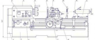
Design
1I611P has 4 main structural units:
1. Headstock. In the middle there is a pulley mounted on a sleeve. This pulley, which causes the spindle assembly to rotate, is connected to the gearbox via four V-belts. From the take-up pulley, the spindle assembly accepts twelve modes of torsion through a toothed clutch. Twelve more innings are passed through a bust. The connection of the coupling with teeth and brute force is carried out using a special handle located on the right side of the headstock. To ensure that the overdrive and clutch never work at the same time, the headstock is equipped with a locking unit. It is also equipped with a unit that increases the pitch of the created cutting, and a snaffle that transmits torsion to the guitar.
Gearbox. The rotation frequency of the spindle assembly depends on it. It contains four axles on which gears of various sizes are installed. The gear drive is the main electric motor of the machine, which is connected to the gearbox via flanges. Thanks to flat guides, the gearbox moves along the cabinet. It is fixed to it with bolts. Belt tension can be changed. A preselective unit, which is controlled by a special flywheel, is responsible for switching rotation modes.
Guitar. Mounted on the left side of the feed box. To form most types of cuts, you do not need to replace the guitar gears. If you need to create cutting with increased precision, replaceable gears are mounted, making it possible to process parts without using a feed box. In order to correctly establish the guitar's performance, it is necessary to study the equipment passport.
Gearbox. This part of the device is structurally closed. The characteristics of the feed box provide all the opportunities to create metric cutting in increments of 0.02-4.8 cm without the use of a set of replaceable gears.
Detailed analysis of the device in the video:
This is interesting: Do-it-yourself metal lathe - video, photo
Features of additional parts
The headstock 1I611P is mounted as follows:
- Center mounted pulley.
- Spindle unit with 20 types of revolutions.
- Handle for shifting clutch and gear.
- Snaffle with devices for increasing step size.
- The tailstock provides clamping of a long part, facilitating its high-precision processing.
- The tailstock can be moved 1 cm in both directions from the center; manipulation allows the use of a wider radius for processing parts.
- The tapered ruler provides the ability to process tapered parts.
- Guitar - located on the left side of the gearbox, for making threads, requires the installation of gears.
- Apron – ensures movement of the caliper. Consists of a roller and a screw provided with a locking mechanism.
Instructions for this process can be found in the device data sheet.
The disadvantage of a turning screw-cutting device is the inability to create pitch threads on it. But given that it is used very rarely, it is worth missing this point.
Before starting work on a lathe, you must carefully study the instructions and follow all rules for operating the mechanism.
Performance characteristics
The equipment passport indicates all areas of application and operational characteristics of the device. In particular, it is permissible to use 1I611P for processing parts up to 12.5 centimeters under the support and up to 25 centimeters under the bed. The number of rotations of the constitutive unit of the device is minimum 10 and reaches 2 thousand revolutions per minute. Cone - Morse category 5, which should be taken into account when choosing products and processing methods. The minimum length is not specified in the passport, but we can say that it is 1-2 centimeters. The maximum possible length of the unit is up to half a meter. Main characteristics of the device:
- spindle diameter - 25 millimeters;
- rod diameter - 24 millimeters;
- spindle end according to state standard - 4;
- maximum stroke - 50 centimeters (this explains the maximum possible length of the processed product);
- longitudinal feed range from 0.01 to 1.8;
- cross feed range from 0.005 to 0.9;
- number of electric motors - three;
- power - 3 kW;
- hydraulic power - 0.08 kW;
- cooling power - 0.05 kW.
Main technical characteristics
Rigidity and precision. These parameters were achieved through the use of a special method of fastening the cutter head without clearance. Welded container containing lubricant, as well as built-in high-precision electrical equipment. The feed box, which is universal, greatly facilitates the work
There is no need to install new gears when cutting threads. A well-thought-out and very convenient system for removing chips that are formed during processing of parts. Spindle speeds are switched according to a special principle, which allows the operator to select and set the required switching in advance, which is very important. A special locking device that allows you to protect the mechanism from various overloads is unique today. This mechanism allows the unit to perform its functions even when using a hard stop. A special function makes it possible to replace belts without necessarily removing the spindle
This significantly saves repair time. Vernier is a very precise mechanism that measures the displacement of the caliper. The frame is made of special cast iron, which is coated with chromium-nickel. This protects the mechanism from corrosion and damage. When performing work on a lathe, in particular thread cutting, lubricant is supplied to the screw automatically. The unit can be operated in very cramped production areas due to the fact that the design of the unit does not provide for its maintenance from the rear.
Important! The machine is ideal for small workshops, boxes or garages. It is quite easy to maintain and carry out preventive maintenance
- The machine guides are characterized by increased strength and wear resistance due to hardening with high-frequency currents.
All of the above features of the IZH 1I611P lathe are certainly important. They greatly facilitate the processing of workpieces and parts, making this process automatic.
You can learn more about the capabilities of the machine, its structure and main functions by viewing
video
Instructions and Application
With the help of IZH 1I611P it is possible to perform turning of cones and cutting of various threads, which we mentioned at the very beginning.
Photo IZH 1I611P
Photo 2: IZH 1I611P
The machine is intended primarily for multi-stage tasks. Here, hardened guides are used, which are characterized by increased accuracy and strength.
Important! Old models are offered on the secondary market in a fairly wide range. This is a mass product that is always in demand
The price ranges from 24,000 to 140,000 rubles.
Equipment documentation
The passport for the 1P611 machine is an operating manual not only for the worker, but also for those who will maintain and repair it. This is a technical document that is attached by the manufacturer to the supplied equipment.
Overview of sections given in the passport:
- purpose and possible areas of application;
- design description;
- specifications;
- transportation and unpacking;
- preparation of the foundation with installation and installation;
- ensuring the working condition of the machine, setting up and starting it in compliance with safety regulations;
- user manual;
- specifications: all equipment components;
- governing bodies;
- gear and worm wheels;
- gears for adjustment when cutting threads;
- ball and roller bearings;
- accessories;
- electrical equipment;
- hydraulic devices (valves, spools, etc.);
Kinematic diagram of the machine
The passport is used by workers, technologists, mechanics and power engineers. Electrical mechanics use electrical circuit diagrams of equipment to perform repairs. Requirements for operational documentation are now regulated by GOST 2.601-2013.
Electrical diagram of the machine
When setting up the machine and accessories, ensure that:
- installation and securing of tools, workpieces;
- location of the coolant supply system pipelines.
- The 1P611 machine is universal and provides increased manufacturing accuracy.
- The machine is set up for processing the part in accordance with the drawing.
- The selection of spindle speeds and feed rates is carried out using the handles on the headstock, where the necessary diagrams and tables are available.
Main technical characteristics
Rigidity and precision. These parameters were achieved through the use of a special method of fastening the cutter head without clearance. Welded container containing lubricant, as well as built-in high-precision electrical equipment. The feed box, which is universal, greatly facilitates the work
There is no need to install new gears when cutting threads. A well-thought-out and very convenient system for removing chips that are formed during processing of parts. Spindle speeds are switched according to a special principle, which allows the operator to select and set the required switching in advance, which is very important. A special locking device that allows you to protect the mechanism from various overloads is unique today. This mechanism allows the unit to perform its functions even when using a hard stop. A special function makes it possible to replace belts without necessarily removing the spindle
This significantly saves repair time. Vernier is a very precise mechanism that measures the displacement of the caliper. The frame is made of special cast iron, which is coated with chromium-nickel. This protects the mechanism from corrosion and damage. When performing work on a lathe, in particular thread cutting, lubricant is supplied to the screw automatically. The unit can be operated in very cramped production areas due to the fact that the design of the unit does not provide for its maintenance from the rear.
Important! The machine is ideal for small workshops, boxes or garages. It is quite easy to maintain and carry out preventive maintenance
The machine guides are characterized by increased strength and wear resistance due to hardening with high-frequency currents.
All of the above features of the IZH 1I611P lathe are certainly important. They greatly facilitate the processing of workpieces and parts, making this process automatic.
You can learn more about the capabilities of the machine, its structure and main functions by viewing
video
Instructions and Application
With the help of IZH 1I611P it is possible to perform turning of cones and cutting of various threads, which we mentioned at the very beginning.
Photo IZH 1I611P
Photo 2: IZH 1I611P
The machine is intended primarily for multi-stage tasks. Here, hardened guides are used, which are characterized by increased accuracy and strength.
Important! Old models are offered on the secondary market in a fairly wide range. This is a mass product that is always in demand
The price ranges from 24,000 to 140,000 rubles.
This is interesting: Do-it-yourself argon welding - diagram, photo, video
Purpose and scope
The 1P611 screw-cutting lathe was designed for operation in premises that do not have solid poured foundations under the equipment. It is used in multi-storey industrial premises and installed in mobile workshops, including steamships. The design of the frame dampens vibration. Technological accuracy does not depend on the position of the equipment. The machine operates stably even when the floor tilts.
Reference. The 1P611 screw-cutting lathe model is available in different climatic options: tropics, north, standard.
The purpose of 1P611 is the production of small series and single parts from steel, cast iron, non-ferrous metals and their alloys. The machine performs roughing of workpieces and finishing of parts with high precision and cleanliness.
Surface treatment
The machine performs cutting of cylindrical and conical surfaces, end processing and thread cutting. Cutters and multi-edge tools are used:
- incisors;
- drill;
- countersink;
- taps and dies.
If it is necessary to strengthen the surface and give it a high class of cleanliness, rolling in with a roller, cleaning with a file and sandpaper is possible. To perform these operations, simple devices are used.
Threading
The guitar is set to the correct gear ratio for thread cutting. Each set of gears corresponds to a specific pitch. The shape of the thread is ensured by sharpening the cutter according to a template.
On model 1P611 threads are cut:
- metric;
- modular;
- inch.
Pipe - conical, made using a special tool.
Threads with a diameter of up to 24 mm, located from the end, are cut with a multi-blade bench tool:
- tap for the inner surface, nut type parts;
- die for external thread: bolts, studs.
To cut them, the tool is mounted on the tailstock.
In areas where it is impossible to use a metalworking tool, the thread is cut with a cutter. To remove the tool, a groove is provided in the drawing.
Important!
The cutter is retracted manually. The turner requires high qualifications to perform the operation: at the same time, the handle of the slide rotates, and the revolutions and feed are turned off with a lever on the apron.
Drilling
On a 1P611 screw-cutting lathe, drilling is performed in the axis of rotation of the part at the end on the tailstock side.
- The drill is inserted into the quill cone.
- The tool is brought to the part. The tailstock is fixed motionless.
- Reverse revolutions are activated.
- By rotating the handle, the quill moves and the drill cuts into the part.
When processing thin long shafts, a steady rest is installed for rigidity. Drilling large holes can take place in 2 stages: first a drill of a smaller diameter, then the required one.
Segment
On the 1P611 model there is no transverse mechanical feed of the cutter. The slide is moved manually using a handle. The cutter is aligned with the cutting edge exactly along the axis of the part. The spindle rotates and the cutting tool is brought in. Cutting with a straight cutter is done in reverse rotation.
Reaming holes
Holes are developed in short parts of large diameter, such as washers, rings, after drilling.
- The cutter is attached to the cutter holder with a stem along the axis of the part.
- Rotation starts.
- The part is processed by moving the caliper along the guides.
Important!
Thin parts are processed manually. With a mechanical feed, there is a high probability that you will not have time to stop the caliper and the tool will crash into the cams.
Countersinking
Long workpieces such as a shaft are clamped at one end in the cams. A steady rest is placed on the tailstock side to prevent beating. A countersink is installed in the quill. It cuts into the center of the end when rotating to a specified depth. Configuration – type, holes for centering, determined by the shape of the countersink.
Specifications
Model 1P611 is a precision screw-cutting lathe. It is designed for cutting metal workpieces and manufacturing parts of complex configurations with high precision.
Main settings
Maximum dimensions of parts machined on the machine:
- workpiece length 500 mm;
- cutter stroke length 450 mm;
- diameter above the bed 250 mm;
- diameter above the caliper is 145 mm.
Cutting accuracy class P.
Spindle. During processing, parts are fixed in a chuck and collet. Spindle dimensions:
- internal Morse cone 4;
- number of rotation stages 14;
- rotation speed 33.5–3000 rpm;
- hole diameter 26.5 mm;
- diameter of the processed rod is 25 mm.
When processing a rolled billet in a collet, its maximum diameter is less - 16 mm.
Caliper. The caliper does not have fast longitudinal and transverse gears. Pitch threads are not cut on the machine. Node characteristics:
- maximum longitudinal movement 580 mm;
- running shaft diameter 20 mm;
- lead screw diameter and pitch – 30×6 mm;
- number of feed stages – 24.
Metric threads are cut in increments of 0.25 - 3.5 mm.
Top slide. The slide moves a maximum of 150 mm. Rotation angle up to 45⁰. The cutter is installed with a holder up to 16 mm.
Tailstock. Morse 3 tailstock quill cone with a diameter of 40 mm. It moves a maximum of 70 mm. The largest horizontal displacement of the upper part of the body relative to the spindle rotation axis is 10 mm on each side.
Electrical equipment. The 1P611 machine has 2 independent motors: drive and coolant.
Dimensions and weight. Net weight of the machine is 560 kg. Dimensions 1510×700×1360 mm.
Machine structure - main components and mechanisms
The components of the machine determine its high technical characteristics and expanded scope of application. The screw-cutting model has a number of advantages due to the use of high-quality and professional parts.
bed
The bed in the IZh machine is stationary. Its disassembly is not required, since the design does not provide for switching modes or lubrication during operation. The frame is shockproof, assembled from high-quality, thick and durable metal. It protects the employee from receiving an electric shock.
Headstock
There is a sleeve pulley in the center of the headstock. It causes the unit to rotate, which is connected to the gearbox by belts. As a result of the operation of the unit, 12 rotation speeds will be obtained, plus the same amount through search.
A mechanism is installed in the headstock that allows you to increase the thread pitch. There is a snaffle required to transmit rotation to the gearbox. Headstock with locking mechanism.
Tailstock
The tailstock in the machine model is of the rounded type. The pintle is responsible for the smoothness of the ride. The device provides a characteristic smooth transition and maintenance during the operation of the cutting tool.
Spindle
The size of the entrance is 2.5 centimeters, while the rod differs on the smaller side by 1 mm. Minimum rotation speed is from 20, maximum up to 2 thousand revolutions per minute. According to GOST, the end is 4, the size of the internal cone is 4 M.
Caliper and apron
The unit of the machine model under consideration, on which the support is located on top, has relatively small dimensions in comparison with other types of equipment. Inside there is a mechanism responsible for transforming the rotational movement of the lead shaft and lead screw.
Gearbox
The stroke length of the carriage is 50 centimeters. The limit of longitudinal feed is up to 1.8, transverse feed is up to 0.9. A distinctive feature is the lack of speed of rapid movements of the caliper (both). Note that the limits of the threads produced (in millimeters):
- metric - 0.2 - 48;
- inch - 24 - 0.5;
- modular - 0.2 - 30.
Gearbox
Reducer of four axles with gears. It is connected to the engine using flanges. The tension of the belts is adjusted by thumbs.
1p611 lathe
1p611 screw-cutting lathe for metal, providing high-precision parts by turning.
To ensure trouble-free operation of the machine, maintain increased accuracy and technical characteristics, you should monitor the technical condition of the equipment, regularly carry out preventive maintenance, and allow only personnel who have studied the manual for using the machine to operate.
Figure - 1p611 screw-cutting lathe
Machine mechanisms
The machine bed is rigid, cast, and is mounted on stands. The cabinets have a welded structure and contain the main motion electric motor, gearbox and electrical equipment. The gearbox performs the function of a gearbox, supporting eight stages of rotation speed. The machine spindle is located in the headstock, which is mounted on the frame on the left. A set of replacement gears is mounted with the headstock and is used to set up the machine for thread cutting. From the guitar mechanism, the movement is transmitted to the feed box.
The machine apron moves in the longitudinal direction and transmits the rotational movement of the transverse feed. The direction of movement of the caliper is limited by two prismatic guides of the frame. The tailstock moves longitudinally along the flat and prismatic guides of the frame.
Download the passport for 1p611 lathe
www.stanoktehpasport.ru
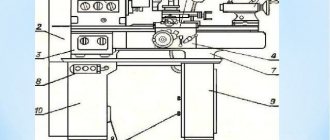
Design of a screw-cutting lathe
Fixed on the frame:
- headstock;
- gearbox;
- guitar;
- electric motors.
A caliper with a tool holder and an apron moves along the guides. The tailstock is on the right.
Headstock
The headstock is the most complex and massive component of the 1P611 lathe. It is located on the left side of the frame, above the guide line.
Several nodes are built into it:
- spindle with bearings;
- feed drive;
- overdrive gears;
- control mechanism.
Thrust and radial bearings take on the load on the spindle and make rotation uniform. Outside the headstock, in the working area, a chuck with cams is attached to the spindle to fix the part.
Guitar
Without a guitar, the machine can work, but it won’t cut threads. A set of gears with a certain number of teeth regulates the pitch - the movement of the cutter over a certain size per revolution of the spindle - of the part.
The guitar's pitch rotates, changing the center-to-center distance between the gears. This ensures high-quality gearing of wheels with different numbers of teeth. In the working position, the end of the slope is clamped with a bolt.
Caliper
The movable support assembly moves the cutting tool along guides along the machine. It has:
- apron with feed control mechanism;
- slide with tool holder.
The lead screw and shaft pass through the apron. There are gear couplings inside. The movement of the cutting tool perpendicular to the axis of the machine is carried out by moving the tool holder along the transverse guides in the upper part of the slide.
Tailstock
The tailstock located on the right side of the guides is used to perform the following operations:
- fixing in the centers of long parts;
- drills;
- countersinking;
- cutting internal threads with a tap.
The horizontal displacement of the quill with the center allows you to sharpen tapered shafts with a small angle. The housing is moved by 2 screws located at the base of the unit.
The tailstock stands on the bed guides and moves along them. It is fixed with clamping bars located at the bottom. The quill with the tool is driven by a handle protruding from the body on the right. A lever in the upper part in front of the body clamps the quill in the working position.
Electrical equipment
The electrical circuit design of the 1P611 machine allows the drive, cooling and lighting systems to turn on and operate independently.
Drive motor
The drive asynchronous electric motor has a power of 1.7 kW and a rotation speed of 3000 rpm. It is installed below, inside the left post of the frame and transmits rotation to the drive shaft through a V-belt drive.
Electric cooling pump
An electric coolant pump with a power of 0.12 kW is located on the right pillar. There are also buttons to start and stop it on the front side of the case. The cooling system is turned on regardless of the operation of the machine drive.
Control switch
The input switch supplies and switches off the voltage of the power and control circuits. The switch starts the spindle head and sets the direction:
- spindle rotation is forward or reverse;
- disabling chuck rotation and braking.
The rotation is turned off and the brake is applied when the handle is returned to the neutral position.
Local lighting
The local lighting lamp is mounted on the back of the caliper body and moves synchronously with the tool. The lamp is a lampshade on a flexible stand. It operates on 36V DC.
Braking resistance
The engine is braked by turning on the reverse current and resistance when the “Stop” button is pressed.
Design features
The machine has the following design features:
- Fixation of the cutting head, but without gap (ensuring rigidity and accuracy).
- There is a container with a container for coolant and a cabinet with electrical equipment.
- Chip removal and collection system.
- Preselector control (preliminary selection of spindle speed for the next processing stage).
- Apron with overload protection and rigid stop when turning.
- Vernier mechanism for precise cross feed.
- On the transverse carriage of the caliper there is a mechanism for performing milling work.
- The caliper is controlled by one handle using a mnemonic principle.
- Lack of controls on the back side (can be placed against a wall).
bed
- Made of chromium-nickel cast iron with two flat and two prismatic guides, which are hardened by high-frequency currents and ground. The frame is fixed to a monolithic pipe. There is also a shelf that protects the lead screw from chips and emulsion. Inside the frame there are:
- Main drive electric motor.
- Reducer for changing spindle rotation speeds.
- Mechanisms of the lubrication and coolant supply system.
- Emulsion container.
- Panel with electrical equipment.
Headstock and tailstock
The front headstock contains:
- spindle unit connected to the gearbox by four V-belts;
- a gear coupling transmitting twelve rotation speeds to the spindle;
- overkill - transfers twelve more using a special handle;
- locking mechanism (prevents simultaneous activation of the clutch and overdrive);
- device for changing the pitch of the thread being cut;
- a bit that transmits rotation to the guitar and then to the gearbox.
The tailstock firmly tightens long parts and increases the accuracy of work. On this machine it can be shifted by 10 mm in both directions in relation to the centers.
Gearbox
Manufactured in closed form. Serves to supply movement to the support for cutting metric threads with a pitch of 0.2–48 millimeters without additional gears.
Gearbox
It is a gearbox consisting of four axles with gears. It is connected to the engine using flanges. The tension is regulated by thumbs.
Gearbox
Responsible for the rotation speed of the spindle assembly. It is driven by the main electric motor connected to it through flanges. The gearbox can be moved along flat guides to regulate belt tension. The speed change is carried out by a preselective mechanism controlled by a corresponding flywheel.
Caliper and apron
A support is a mechanism for attaching and moving tools and accessories for processing parts. The design allows the tool holder installed in the upper part to move in any direction. The longitudinal movement is provided by the carriage, and the transverse movement is provided by the slide.
The apron is located at the bottom of the caliper. The device is responsible for the longitudinal and transverse feed of the caliper. Movement is possible in manual and automatic mode. The apron contains:
- four clutches - control the direction of feed;
- drive shaft - produces translational movement of the caliper;
- the lead screw moves the carriage in the longitudinal direction;
- feed control panel;
- A locking device that makes it impossible to turn on the propeller and the drive shaft at the same time;
- Overload protection mechanism.
Spindle
The spindle is a hollow shaft with a conical hole. Rigidly mounted on bearings in the headstock. Has an internal Morse taper for fastening tools (for example: collet clamps). On the outside there is a thread for attaching a faceplate with a chuck.
High-quality fastening of spindle bearings is important
Electric scheme
The electrical circuit contains:
- The main drive is a three-phase asynchronous motor with a power of 3 kW.
- Drive motor for the lubrication supply mechanism.
- Coolant pump motor.
- A transformer that produces a voltage of 36 V for the lighting lamp, 60 V for the braking system and 127 V for the control circuits.
- Protection devices and thermal relays.
Features of additional parts
Some components are designed differently from other lathes.
In the headstock:
- the pulley is installed in the center;
- the spindle unit has twenty rotation speeds;
- guitar to expand types of thread cutting;
- bit with devices for increasing the step size.
The tailstock securely clamps the long workpiece. Can be moved 1 cm on both sides from the center. Expands the range of types of parts processing. The tapered ruler on the caliper makes it possible to process tapered parts.