Machine 1516. Rotary lathe. Specifications
The technical characteristics of the 1516F1 machine are the main indicator of the machine’s suitability for performing certain jobs on the machine. For rotary lathes, the main characteristics are:
- The largest diameter of the workpiece
- Maximum height of the workpiece
- The largest weight of the processed workpiece
- Faceplate revolutions per minute
Below is a table with the technical characteristics of the vertical turning machine 1516. More detailed technical characteristics of the machine can be found in the passport of the machine 1516, which can be downloaded below.
| Name of parameters | Unit. | Quantities |
| Maximum workpiece diameter | mm | 1600 |
| Maximum workpiece height | mm | 1000 |
| The largest mass of the processed workpiece | kg | 8000 |
| Faceplate diameter | mm | 1400 |
| Faceplate rotation speed range | rpm | 1.0…200 |
| Working feed range | mm/rev | 0.02…10 |
| Main drive motor power | kW | 30 |
| Dimensions (LxBxH) | mm | 3170x3025x4100 |
| Machine weight | kg | 18100 |
Attention! The technical specifications given in the above table are for reference only. Machines produced by different manufacturers and in different years may have characteristics that differ from those given in the table
Passport details
Vertical lathe 1516 passport, which contains additional characteristics:
- accuracy class – N according to GOST 8-71;
- remote control of tool selection – Yes;
- remote feed control – Yes;
- T-shaped slots, size - 28H13 mm;
- motion control dials with a division value of 0.05 mm.
Download the passport (operating instructions) of the rotary lathe 1516
Characteristics and features of 1512
Approximate values of the main indicators for the basic configuration of the model are given in the table:
| Technical parameters, unit of measurement | Operating range or limit |
| Accuracy class taking into account the requirements of GOST 8-77 | N |
| ᴓ of the workpiece, mm | Up to 1250 |
| The same, height, mm | Up to 1000 |
| ᴓ faceplates, mm | 1120 |
| Its rotation frequency, rpm | 5-250 |
| Weight of the workpiece, kg | Up to 3200 |
| Main drive power, kW | 30 |
| Machine weight, kg | 16,5 |
The exact technical characteristics depend on the configuration; in modern 1512 models, the weight of the workpiece has been increased to 5000 kg, while the weight of the machine itself has decreased to 14.8 and power consumption has increased to 50.5 kW. General design features include:
- Large dimensions and monolithic frame.
- The presence of a round stable table with a complex configuration, namely a cast iron body with stiffeners and annular projections in the upper part. With this design, vibration is evenly dampened on the machine, processing waste and oil emulsion do not get inside it, and heavy and large workpieces are successfully placed on the table itself.
- The location of the feed box and side support in a protective cast-iron housing is on the right side of the end, with torque transmitted through 6 shafts with constant but not rigid engagement. In this case, the rotation speed of the faceplate is changed remotely; the number of revolutions directly depends on the weight of the workpiece being processed.
- The presence of a vertical support unit with a 5-position head, moving in both vertical and horizontal directions. The movement is carried out due to independent drives, in the first case it is provided by the guides of the unit itself, in the second by rectangular traverses. With this design, the caliper rotates in both directions and bends up to 45°, which in turn allows the production of spherical and conical parts.
- The presence of a side support that duplicates the movements of the upper one in order to increase the processing accuracy and equipment productivity.
Application benefits
The 1512 machine was distributed throughout the territory of the former USSR and was successfully exported to other countries, its characteristics have been tested in practice and confirmed by consumer reviews. The model has proven itself to be reliable and unpretentious; its main advantages include:
- Availability of carbide cutting tools, the ability to process a variety of materials and metals with any composition and degree of hardening.
- Rigidity and stability of the cast housing.
- High drive power, ensuring good accuracy and speed of processing workpieces, including large-format ones.
- A wide range of changes in the feed parameters of individual units, which in turn has a positive impact on the technological capabilities of the rotary machine.
- The design and kinematic diagram are well thought out, ensuring the transfer of forces with minimal energy losses and wear of working elements during the processing of parts.
- Versatility and the ability to process a variety of parts both in small batches and in mass production conditions.
Single-column turning lathe 1516. Purpose and scope
The single-column rotary lathe model 1516 is a universal machine and is designed for processing a variety of products made of ferrous and non-ferrous metals in small-scale and mass production.
Model 1516 is common among rotary lathes in the former USSR. The machine allows turning parts with a diameter of up to 1600 mm, a height of up to 1 meter and a weight of up to 6300 kg . The machine was exported to many countries around the world.
The design of the 1516 machine is unified with the design of the 1512 machine and differs only in the dimensions of the faceplate and the power of the electric motor.
The machine can perform cylindrical and conical turning and boring, turning of planes, drilling, countersinking and reaming of holes, as well as semi-finishing and finishing turning of flat end surfaces.
Operating principle and design features of the machine
The machine has two supports :
- vertical with a five-position turret with automatic rotation and locking at each position
- horizontal (side) with four-position tool holder
The technological capabilities of the machine are significantly expanded with the help of a self-centering faceplate supplied upon special order, devices (for thread cutting, processing of conical surfaces, turning shaped surfaces of bodies of revolution along a copier, processing parts on stops) and a device for processing with cooling.
The following operations can be performed on the machines:
- turning cylindrical and conical surfaces;
- boring of cylindrical and conical surfaces;
- turning flat end surfaces using vertical and lateral supports.
In addition, a vertical support can be used to grind flat end surfaces while maintaining a stepwise constant cutting speed in finishing and semi-finishing modes; drilling, countersinking and reaming; Grooving and parting.
When using special devices and devices that are supplied with the machines upon special order for an additional fee, the machines can produce:
- processing of parts according to specified dimensions (on stops);
- cutting threads, turning and boring conical surfaces;
- processing of shaped surfaces of bodies of rotation using a copier (electrocopier);
- processing of parts with cooling.
In the usual version, the machines are supplied with a vertical turret support, which has a mechanical rotation and clamping of the turret head, and a side support.
In addition, upon special order, for an additional fee, a machine with a self-centering faceplate with manual clamping of the product can be supplied.
All accessories can be mounted on the machine at the same time, with the exception of cooling, which cannot be installed simultaneously with the self-centering faceplate.
Due to the fact that the installation of fixtures requires significant changes and modifications to the machine, orders for the manufacture of fixtures for previously supplied machines cannot be fulfilled. Accessories are supplied only with the machine.
The significant power of the main drive electric motor, the high rigidity of the base parts and the sufficient strength of all elements of the kinematic chain, combined with wide ranges of control of the faceplate speeds and feed rates, allow the machines to perform highly productive work at high-speed cutting conditions.
Main technical characteristics of screw-cutting lathe 1516
Developer: Krasnodar Machine Tool Plant named after Sedin.
Manufacturer: Krasnodar Machine Tool Plant named after Sedin.
The main parameters of the machine are in accordance with GOST 44-93. Rotary lathes. Basic parameters and dimensions. Standards of accuracy and rigidity.
- Machine accuracy class N according to GOST 8-77.
- The largest diameter of the workpiece being processed is Ø 1600 mm
- The highest height of the processed workpiece is Ø 1000 mm
- Diameter of the washer - Ø 1400 mm
- The largest weight of the processed workpiece is 6300 mm
- Faceplate rotation speed - 4..200 rpm, 18 steps
- Electric motor power - 30 kW
- Full weight of the machine – 20 t
Modifications of the rotary-turning machine, single-column 1516
1516.000, 1516-1, 1516-2, 1516.300, 1516.400 - universal single-column rotary lathe
1516F1, 1516PF1, 1516F1.041, 1516F1.300, 1516F1.323, 1516F1.4 00, 1516F1.423 - rotary lathe with digital display — digital display device
1516F2, 1516F3, 1516F3.271, 1516F3.471, 1516MF4 - rotary lathe with CNC - numerical control device
Description and purpose of equipment
This lathe is suitable for medium-scale production of cylindrical products of large diameter and relatively short length. Their material can be various grades of steel and other types of alloys. The choice of tool depends on the structure of the future product
The design is single-column, with a faceplate at the bottom and two calipers at the top. This arrangement simplifies loading and unloading of products and reduces the load on all components, including the electric motor.
The calipers differ in design - one of them is vertical, the other is horizontal. This allows you to maximize the number of cutting types and cover the workpiece on internal and external surfaces.
Allowed types of processing:
- turning of cylindrical and conical surfaces;
- boring holes;
- turning flat end surfaces;
- cutting grooves;
- trimming;
- thread cutting;
- milling;
- grinding;
- drilling;
- creating curved surfaces using special tools.
Some of the listed operations require retrofitting the 1516 machine.
General information
The machine tool plant in Krasnodar named after Sedin produces carousel machines model 1516.
Vertical turning lathe 1516 is a machine used in industries with a small number of parts produced. It is used to process workpieces by cutting metals and alloys.
The design of the machine is single-column. To expand the surface processing area, the model is equipped with two supports. One is vertical. A five-position turret is attached to it. Tool change, spinning and clamping are carried out in semi-automatic mode. The second support is horizontal. A tool holder for 4 tools is attached to it.
The capabilities of the 1516 machine allow you to carry out the following types of processing on cylindrical parts:
- turning from outside and inside (straight, conical);
- boring from outside and inside (straight, conical);
- turning the ends of any of their supports.
To expand technological operations on rotary lathes, in agreement with the customer, it is additionally equipped with devices that produce:
- thread cutting;
- caliber turning;
- turning on stops;
- turning with coolant.
Main advantages
The 1516 rotary lathe and its modifications have been produced for almost fifty years. This model has not yet lost its popularity and is widely used both at manufacturing enterprises in the post-Soviet space and abroad.
Reliable design and outstanding technical characteristics provide the 1516 vertical turning lathe with a number of noticeable advantages over other types of turning equipment. Among them are:
- massive cast stand and table body, ensuring rigidity and vibration resistance of the machine even when processing at extreme conditions;
- wide range of adjustment of tool movement speeds;
- the presence of a five-position turret as standard;
- ease of loading and centering of large-sized workpieces;
- low labor intensity and ease of installation - the machine is supplied in the form of large assembly units;
- low price for a machine of this size and such technological capabilities.
In addition, the 1516 machine is famous for its simple design, reliability and durability in operation. Its repair does not require any special skills or knowledge and is therefore within the capabilities of the company’s repair personnel.
Design features and maintenance requirements
Main components and mechanisms of the machine:
Bed - the supporting part to which all the main elements are attached, including the body
It is important to securely fasten the machine to the foundation to prevent vibration. In addition, a reinforced layer of concrete is required, taking into account the weight of the structure. A table that provides positioning of the future part. This is a rough cast iron casting equipped with many stiffening ribs. Such a design is capable of withstanding very heavy loads
If necessary, its plane is restored. Faceplate with built-in workpiece clamping mechanism. The safety of work and the quality of processing depend on the serviceability of the module, since a significant load is applied during the cutting process. During operation, the faceplate rotates. When working, it is necessary to cover it with a protective casing that prevents chips from flying away, splashing coolant and protects in case of tool splitting. When readjusting, the casing is moved to the side without interfering with access. Dynamic rotation parameters are set using a gearbox. Racks with a crossbar for the vertical layout of machine parts. They are made with a significant margin of safety and are able to withstand emergency situations. A traverse with two calipers moves along the racks and can be locked in the desired position. One of the supports is a revolving one - it consists of a carriage and a slider with a revolving head, which houses the cutting tool. The second one is determined by the boring machine, and it has a tool holder on its slide. There is also a side support for external processing. Rotations of the sliders expand the technological capabilities of the existing tool. A control panel mounted on a rod to the operator's workplace. This allows you to control the machine, controlling the cutting processes taking place. All buttons are at hand, and if necessary, you can always quickly adjust or stop processing. Feed box with drive. Lubrication station. The process occurs centrally, by supplying tool oil to certain lubrication points. The worker is required to monitor and maintain the level of lubricants in the system. Electrical cabinet. Power is supplied from an industrial three-phase electrical network. During installation, it is necessary to ensure free access to both the electrical cabinet and other parts of the equipment.
A full description is provided in the accompanying documentation. The requirements for operation, safety precautions and routine maintenance are also indicated there. Timely maintenance can significantly prolong repairs and avoid many different breakdowns. If wear is detected, for example, on gears, it is better to replace them immediately rather than wait for errors to accumulate.
Depending on the intensity of use, the timing of diagnostics, medium and major repairs is determined.
Specifications
The versatility of the machine and the number of technological operations that can be performed on it directly depend on the technical characteristics of the equipment. The rotary turning unit under consideration belongs to machines of normal accuracy class. Technical characteristics of the unit:
- maximum diameter of the workpiece being processed is 160 cm;
- the greatest height of the workpiece that can be processed is 1 meter;
- faceplate rotation range – 1–250 rpm;
- stepless adjustment of the faceplate rotation speed;
- the faceplate rotation speed has 2 stages;
- the electric motor has a power of 55 kW;
- the crossbar moves at a speed of 45 m/min;
- horizontal movement of the caliper is 95 cm;
- movement of the caliper slider in the vertical direction – 70 cm;
- number of positions at the turret head – 5;
- crossbar travel distance 65 cm;
- the tool holder has 4 positions;
- the caliper has 18 feeds;
- caliper feed limits in the range of 0.03–12.5 mm/rev;
- the maximum torque allowed according to technical documentation is 25 kNm.
Also optionally installed on the machine is a cooling system, a module for thread cutting, as well as for turning curved surfaces. Such additional tools and mechanisms can significantly speed up the operation of the machine and increase its productivity.
Workspace dimensions
The working space of the 1516 rotary lathe is one of its most important characteristics. It is determined by the maximum dimensions of the workpiece being processed and the range of movements of the supports and crossbar, on which the positioning of the tool during turning depends.
Maximum dimensions of the workpiece in horizontal and vertical planes:
- maximum diameter - 1600 mm;
- maximum height - 1000 mm.
Vertical support stroke limits:
- vertically - 700 mm;
- horizontally - 950 mm.
Side caliper stroke limits:
- vertically - 1000 mm;
- horizontally - 630 mm.
The greatest vertical movement of the cross member is 660 mm.
Safety precautions at work
The large-sized lathe 1516 is an object of danger if operating rules are violated. Therefore, only persons who have undergone appropriate training and have qualifications are allowed to work with it
It is important to follow basic safety precautions:
- it is necessary to work strictly in special clothing and shoes;
- tuck your hair under your headdress; there should be no hanging edges of clothing;
- at idle, you must initially check the operation of the controls, as well as the serviceability of the lubrication and cooling system;
- before starting work, make sure that the machine is grounded;
- It is prohibited to approach the equipment while under the influence of alcohol, drugs, or medications.
For safety, be sure to check the proper condition of the locking mode of the on and off levers to prevent spontaneous switching from idle to working.
The 1516 rotary lathe is one of the most reliable options for turning equipment designed for processing large-sized workpieces made of ferrous and non-ferrous metals, as well as various alloys. The unit provides the ability to perform a variety of operations, therefore it is considered a universal machine and is popular among workshop workers. The main advantage is the ability to process parts weighing up to 6 tons.
https://youtube.com/watch?v=ougw705-mQU
Opportunities from a technological point of view
The main purpose of rotary machines is to process relatively flat parts with a round configuration. Among the possible preparations:
- Gears.
- Wheel installations.
- Flywheels.
- Lids.
- Flanges.
- Disks.
The installation uses standard tools, including reamers, countersinks, drills, heads with cutters, and the like. The main technological operations for the device include:
- Making holes using a rod tool.
- The function of boring through and stepped holes.
- Cutting grooves in the shape of a circle.
- Grinding of ends, ledges.
- External turning of parts in the shape of a cone or cylinder.
The range of operations performed expands with the addition of special equipment:
- Lapping, rolling using rollers.
- Sanding, superfinishing.
- Thread cutting.
- Deep drilling.
- Processing of nonlinear surfaces, including spherical ones.
Adjustable clamps make it easier to secure workpieces if necessary. The same goes for the cams. Small parts are installed in additional self-centering chucks.
Design and operating characteristics of the main components of the 1531m rotary lathe
Design and main components of the 1531m rotary lathe
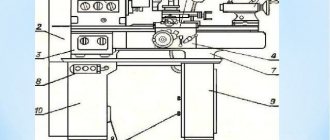
Machine bed
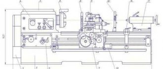
The machine bed consists of a base 1 and a stand 8 rigidly connected to each other. In the inner part of the base 1 there are bearings for the spindle of the faceplate and its ring guides. The rack 8 has vertical guides for moving the cross member 15 and the carriage 4 of the side support 12. In the internal cavity of the rack under the door 11 there is a cabinet with the electrical equipment of the machine.
Faceplate
Faceplate 2 with four cams fixed in its T-shaped slots is intended for installation, fastening and rotation of workpieces. To clamp the product, each of the cams is moved by a separate screw with a square shank.
Cross member
The cross member 15 serves to install the vertical support 16 at a height convenient for processing products. Raising or lowering the cross member is carried out by a mechanism placed in box 7.
Vertical support
The vertical support 16 is designed to move tools installed on it that process the internal and upper surfaces of products. It consists of a carriage 17, a rotary slide 18, a slider 19 and a turret 34.
The carriage 17 can move along the guides of the cross member 15 to move the caliper in the horizontal direction. If horizontal movement of the carriage is not used, then for a more rigid position it is fixed to the crossbar guides. The carriage is moved manually using a square shank 26.
The rotary slide 18 is located on the carriage 17 and has guides for the movement of the slider 19. Using the square shank 21, you can rotate and set the slide at the angle necessary for processing conical surfaces of workpieces.
The slider 19 is designed to move the turret 34 mounted on it in the vertical direction. If the vertical movement of the slider is not used, then it is fixed on the guide slide 18. The mass of the slider is balanced by the load 20. The slider is moved manually using a square shank 24.
Turret head 34 has five sockets designed for installing and fastening tool holders. Spinning, turning 1/5 of a turn and clamping the turret head on the slider 19 is done by handle 5.
Turret
Turret head 34 has five sockets designed for installing and fastening tool holders. Spinning, turning 1/5 of a turn and clamping the turret head on the slider 19 is done by handle 5.
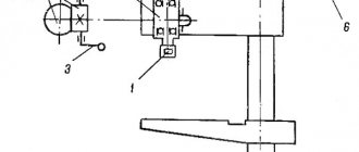
Side caliper
The side support 12 is designed to move in vertical or horizontal directions the cutters installed in the cutting head 32 for processing the side surfaces of products. The support consists of a carriage 4, a slider 3 and a cutting head 32.
The carriage 4 can move from the feed mechanism or quick installation movements along the vertical guides of the 8 rack. The carriage is balanced by a load connected to it by a 10 cable and located inside the 8 rack.
Precise movement of the carriage in the vertical direction is carried out manually by rotating the flywheel 31, which has a dial with a graduation value of 0.05 mm.
If the vertical movement of the carriage is not used, then it is fixed to the guides of the rack 8.
The slider 3 moves along the horizontal guides of the carriage 4. The cutter is set to a given position manually by moving the slider 3 while rotating the flywheel 29 with a dial with a graduation value of 0.05 mm.
If the horizontal movement of the slider is not used, then it is fixed to the carriage guides.
The cutting head 32 has four slots for attaching the cutters. To install the next cutter in the working position, the head is turned manually, and it is clamped or pressed by turning handle 33.
Gearbox
The 1531m machine has two identical feed boxes 23 and 30 for vertical and lateral supports, respectively. Each box has two handles. The handle with disk 22 is designed to set the desired feed amount, and the handle 25 is designed to turn on the set feed.
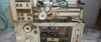
Description of the main components
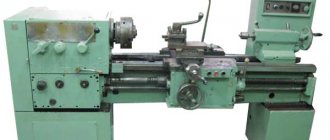
Photo 1. General view of the machine. The basis of the structure is a vertical hollow post cast from cast iron. All other nodes are attached to it.
Desktop
Rice. 1. Drive platform.
The unit (Fig. 1) consists of a faceplate assembled with a spindle on two bearing supports in a cast iron housing, and a drive device. Cylindrical roller bearings are designed to center the platform and absorb radial cutting forces. The radial clearance in the supports is selected by tightening the inner rings with a conical surface using adjusting nuts. The axial load from the weight of the workpiece and cutting forces is absorbed by an annular sliding guide equipped with central lubrication. The rotation of the faceplate is communicated using a cylindrical helical gear from the drive shaft connected to the main movement drive.
Gearbox
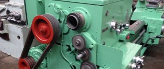
Photo 2. Appearance.
This unit, nicknamed the “pig” by carousel workers (photo 2), serves to transmit torque from the drive motor to the worktable spindle, as well as to set the required peripheral speed of the latter. The mechanism consists of 6 shafts that transmit power flow through gears. All of them are in constant engagement, but there is no rigid closure (the gears sit freely on the shafts). Switching on a particular rotation speed is carried out by switching electromagnetic clutches (there are 10 in total in the box) remotely.
Significant inertial masses (faceplate plus workpiece) lead to an increased starting current at the moment the engine is turned on. To reduce it, stepwise acceleration of the platform is used. Depending on the set speed, switching is automatically carried out in 2, 3 or 4 stages. Since the clutches can be changed on the fly, this allows you to maintain a constant peripheral speed when turning long end surfaces.
Attention: the instructions limit the angular speed of the platform in accordance with the mass of the workpiece being processed. For example, with the mass of the latter being 3.2 tons, the permissible number of revolutions of the faceplate is no more than 80
Characteristics of the electrical equipment of the machine 1516
The electrical equipment of machine tools consists of electric motors, electrical controls, limit switches to limit the movement of moving parts of the machine and control equipment.
The machines are equipped with five three-phase asynchronous electric motors with a squirrel-cage rotor:
- main drive motor 1M1;
- oil pump drive motor 1M2;
- cross member movement motor 1M3;
- motor for installation movements of the upper support, installation movements of the side support 4M1 and three single-phase asynchronous capacitor electric motors with a squirrel-cage rotor to drive the lubricator of the lubrication system;
- cross member motor 1M4;
- upper support motor 2M2 and 2M3
The following voltage values are accepted on the machine
- 380V three-phase alternating current, frequency 50 Hz - power supply of power circuits;
- 110V single-phase alternating current - power supply to coils of magnetic starters and single-phase electric motors;
- 36V single-phase alternating current - power supply for the circuit for selecting the direction of travel of the stepper finder;
- 24V - DC power supply for local lighting lamps;
- 24V - DC power supply for control circuits and electromagnetic couplings;
- 90V - DC power supply to the stepper finder coils.
All electrical equipment for controlling the machine is located in the niche of the machine. The machine is controlled from a pendant control panel.
The electrical equipment of the machine performs the following functions:
- Faceplate control:
- start-up in operating mode;
- start in jog mode;
- step change in speed with a rotating faceplate;
- maintaining a stepwise constant cutting speed when turning end surfaces with the upper support (changing the speed of rotation of the faceplate using a cam rack and a limit switch);
- faceplate stop.
Caliper control:
- working feeds (feed selection and switching on);
- installation movements (selection of movement speed and switching on).
Moving the cross member.
Description of the hydraulic circuit of the model 1541 rotary machine
Control of the main drive of the machine. When the faceplate rotation speed selection handle is set to the position corresponding to the required rotation speed, a switching circuit for the electromagnets of distributors 6, 7, 8, 9, 10 is prepared. Pump 3, through filter 1 and check valve 2, sucks oil from the hydraulic tank and through plate filter 4 along the line 29 supplies it to the distributor 26, which is turned off at this time. Then the oil along line 35 through the needle throttle 24 enters under the locking piston of the cylinder 22 for fixing the position of the gears and lifts the locking piston up, thereby releasing the gear shift rods of the gearbox. Having risen upward, the locking piston allows oil access to the oil distributor and from it into the cavities of the gear shift cylinders corresponding to the selected rotation speed. Distributor electromagnets 6, 1, 8, 9, 10 are switched on.
When you press the “Start faceplate” button, the distributor electromagnet 26 is turned on and the oil enters the clutch engagement cylinder 13. The cylinder rod begins to move to the right until the drain hole opens. The clutch forks must be adjusted so that in this position the clutch begins to work with slipping, rotating the gearbox gears at a “creeping speed”. At the same time, oil enters cylinder 23 under the piston, which rotates the gearbox gears through a rack to facilitate shifting.
When switching to the start position of the distributor 26, line 35 is switched on to drain. No longer held in the upper position by oil pressure, the piston-retainer of cylinder 22 tends to fall down under the action of a spring. To prevent the gears from becoming tooth-to-tooth, switching is performed at the “creeping speed” of the clutch.
Having descended, the piston-clamp of the cylinder 22 for fixing the position of the gears closes the drain hole of line 32, and the starting clutch is fully engaged. At the same time, line 34 is closed and the pressure is removed from cylinders 15, 16, 17, 18, 19, 20, 21, 25, and line 35 is turned on to drain and the spring returns the piston of cylinder 23 to its original position.
When you press the “Stop faceplate” handle, the electromagnet of the distributor 26 is turned off and its spool is moved by a spring to the upper position. Oil is supplied to brake cylinder 14 and the faceplate stops.
Throttle 12 is used to adjust the activation time of the working clutch and brake. Instant activation of the working clutch or brake when switching the faceplate rotation speed can lead to an accident.
Throttle 24 is used to adjust the lowering time of the latch. When lowered quickly, the lock will lock the triple gear unit in the middle position, preventing it from moving from one extreme position to another. In this case, the rotation speed of the faceplate will not correspond to the selected one, and when braking, when the latch rises, the triple block switching will continue. To prevent this phenomenon, the system is equipped with a locking mechanism with a microswitch, which eliminates the possibility of turning on the distributor 26 if the position of the triple gear block does not correspond to the position of the rotation speed selection handle.
The hydraulic system of the machine provides for the possibility of abruptly starting and stopping the faceplate when using its two lowest rotation speeds, which is carried out using distributor 11. This distributor is turned on when using all faceplate rotation speeds except the two lowest indicated. When you set one of the two lowest rotation speeds with the rotation speed selection handle and turn on the “Start” button of the faceplate again, the distributor 11 is turned off, and the oil passes both through the throttle 12 and through the grooves of the valve spool 11, which ensures a quick supply of oil to the operating cylinder 13 clutch When the faceplate is turned off, the oil is also drained through distributor 11, which ensures an abrupt stop of the faceplate.
The cross member is released as follows: oil is supplied by pump 3 through line 29 to the distributor 6. When one of the cross member movement buttons is pressed, the distributor 6 is turned on, and oil through line 31 enters the cross member clamp cylinder 5 and releases the cross member clamping arms; then the limit switch 5VK turns on the motor for moving the crossbar and its movement begins. At the end of the movement, the engine turns off and, at the same time, the distributor turns off, stopping oil access to cylinder 5 and connecting cylinder 5 to drain line 30. Under the action of a spring, the cylinder returns to its original position.
Electrical equipment
The electrical equipment of the 1516 machine consists of electric motors, controls and safety switches.
Power supply circuit for the 1516 machine
To operate the machine and control it, currents with different voltages are used. Thus, the voltage in the general power supply network is 380 V. The coils on magnetic starters use a voltage of 110 V AC. The clutches located in the speed and feed boxes, as well as local lighting, are organized at 24 V. The step finder uses a voltage of 36 and 90 V.
Description of the electrical circuit of the machine 1516. It is equipped with motors whose rotors are squirrel-cage and carry out: the main movement on the machine, the supply of tools, as well as the crossbar and lubrication system.
The electrical circuit for controlling the drives is shown in the photo. The control equipment is located in the niche of the frame. The machine is controlled using a remote control.
Wiring diagram of machine drives 1516
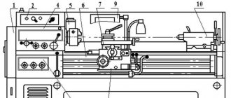
List of components of the machine 1516
- Table – 30
- Faceplate guard - 31
- Vertical support - 650
- Control pendant - 990
- Control panel suspension - 99
- Crossbar - 50
- Cross member movement mechanism - 57
- Bed - 10
- Mechanism for manual movement of vertical support - 420
- Vertical support feed box - 40
- Gearbox - 21
- Casing - 25
- Mechanism for transmitting movement to feed - 15
- Lubrication - 34
- Horizontal caliper (side) - 66
- Feed box horizontal caliper (side) - 46
A distinctive feature of the design of the machines is that most assembly units are made as independent products, which facilitates assembly not only during the manufacturing process, but also during repairs.
Parameters of electrical elements
The electrical equipment of the 1516 rotary lathe includes the following main elements:
- three-phase and single-phase asynchronous electric motors with voltages of 380 and 110 V,
- electric couplings (DC 24 V),
- limit and travel switches (DC 24 V),
- relay switching control equipment (24, 36 and 90 V DC and 110 V AC).
Three-phase electric motors are used in the main drive, oil pump, crossbar and side support positioning mechanisms, and single-phase motors are used in the lubricator drive and in the working feed motors. Control circuits, electric couplings, indicator and lighting lamps are powered by 24 V DC. A voltage of 90 V is used to power the electromagnetic windings of the step finder.
Main functions of the electrical equipment of the machine:
- starting and stopping the main drive, operating mechanisms and lubrication system,
- selecting the direction and setting the number of revolutions of the faceplate,
- setting the positioning speed of the cross member and calipers,
- setting the value and selecting the working feed stage.
All relay switching equipment is located directly on the machine.
Specifications
Considering the technical characteristics, we will also pay attention to deciphering the name of the machine 1512, which was given in accordance with previously introduced standards: the first digit indicates membership in the turning group, the second in the rotary-turning subgroup, the next two - the maximum size of the workpieces installed. The main technical characteristics are as follows:
The maximum height of the cutting tool above the table is 1,000 mm. The workpiece weight limit is 5,000 kg. The installed faceplate can rotate at a frequency from 1 to 250 rpm. At the same time, the manufacturer included in the passport information about the presence of two rotation speed shift gears. The adjustment is stepless. The electrical circuit provides for the installation of a main electric motor, which has an impressive power of 55 kW. This information determines that the 1512 rotary lathe is placing a significant load on the facility's power supply. The traverse can move in the vertical direction over a distance of 660 mm
Movement is limited by mechanical stops. The machine layout also determines the presence of a support, which can move horizontally by 775 mm and vertically by 700 mm. When choosing a cutting mode, you should pay attention to the fact that the maximum permissible force at the time of processing is 35 kN. There is a mechanism for rotating the slider at an angle of no more than 45 degrees. The installed turret has 5 positions. It is mounted on a cylindrical bushing
The master changes the cutting tool by pressing the corresponding key on the control panel. Rotation is transmitted from an electric motor through gears. The main support can move vertically by 1,000 mm, horizontally by 630 mm, the maximum cutting force is 25 kN. The position of this element can be set at a speed of 2,000 mm/min. The passport also contains information that this caliper has 18 feeds.
When choosing this model, it is worth considering that its weight is 14,800 kg. This point determines the presentation of special requirements for the base on which the equipment will be installed. The electrical circuit of the equipment determines its connection to a three-phase network with a voltage of 380V.
Foreign-made equipment
The modern market offers a large assortment of carousel-type units produced at foreign enterprises, and there are several brands that are popular. Among them are the Chinese company Dalian Guofeng Machine Tools, which produces C series equipment:
- 5231, 5240, 5250, 5263. Installations with two racks, having indicators similar to those of the Soviet machines discussed above. The manufacturer guarantees high precision in processing metal blanks when performing the entire range of turning operations, including when working with blanks of complex shapes.
- 5110, 5116, 5123, 5125, 5131. Single rack units whose power can range from 22-45 kW. The equipment is equipped with a CNC, whose simplicity makes working with the device easier, making it more efficient. They have a highly reliable design and are characterized by servomotors mounted on the drives of the X and Z axes.
Carousel-type devices manufactured by the Swiss company ENCE GmbH have a higher price, comparable to the quality. They are presented in several series and are also very popular.
- LEN 3000-5000. The diameter of the blanks for which these models are designed varies between 3150-5000 mm. This equipment is not equipped with CNC, but it is possible to equip it with such a system, which is provided for by the design. The main drive has two stages and is equipped with an electric motor whose rotation speed can be varied in 16 steps. Guides located vertically are sliding, and those located vertically are hydrostatic, acting as unloading elements;
- LEN 1250-2000. The cross-section of the blanks processed on these models is 1250-2000 mm. The series installations are equipped with roller guides with high-precision rolling bearings, which are installed in their moving units. Machining accuracy is enhanced by hydraulically balanced vertical and four-position tool holders. The reliability of the installations is increased due to the installation of electrical equipment from the manufacturer Siemens;
- SEN 1000-1800. CNC machines from well-known manufacturers Siemens and Fanuc. One of the important design features of these installations is a servomotor equipped with a gearbox from a German manufacturer and a thermally symmetrical group faceplate. The units of this series are produced in three standard categories, characterized by high performance and low noise levels - standard, heavy and high-precision.
The domestic market also includes installations from European manufacturers (VWEN and SENQ), which are equipped with a numerical control unit. These devices are notable for the fact that they can process not only workpieces made of various metals, but also alloys that contain porcelain or ceramics. The cross-section of the workpieces can reach 10 meters.
Video: rotary lathe 1516F1 with digital display.