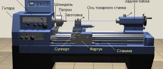
Headstock
The parts located in the headstock serve to support and rotate the workpiece during processing. There are also units here that regulate the speed of rotation of the part. These include:
- spindle;
- 2 bearings;
- pulley;
- gearbox responsible for adjusting the rotation speed.
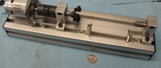
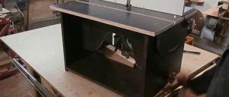
The headstock is separate from the machine
The main part of the headstock in a lathe is the spindle. On its right side, facing the tailstock, there is a thread. Chucks that hold the workpiece are attached to it. The spindle itself is mounted on two bearings. The accuracy of the work performed on the machine depends on the condition of the spindle assembly.
Gearbox top view
In the headstock there is a guitar of interchangeable gears, which is designed to transmit rotation and torque from the output shaft of the gearbox to the feedbox shaft for cutting various threads. Adjustment of the caliper feed is carried out by selecting and rearranging various gears.
Guitar of replacement gears for Optimum lathe
Guitar of a Soviet metal lathe
Maintenance
Spindle
It is unlikely that you can still find a metal lathe with a monolithic spindle. Modern machines have hollow models, but this does not simplify the requirements placed on them. The spindle body must withstand without deflection:
- parts with heavy weight;
- maximum belt tension;
- cutter pressure.
Special requirements are imposed on the journals on which they are installed in bearings. Their grinding must be correct and clean, surface roughness no more than Ra = 0.8.
In the front part the hole has a conical shape.
Bearings, spindle and axle must, when operating, create a single mechanism that does not have the ability to create unnecessary runout, which can result from incorrect boring of the hole in the spindle or careless grinding of the journals. The presence of play between the moving parts of the machine will lead to inaccuracy in processing the workpiece.
The spindle is stabilized by bearings and a tension adjustment mechanism. It is attached to the right bearing using a bronze bushing bored out to the shape of the neck. On the outside, its bore coincides with the socket on the headstock body. The bushing has one through hole and several cuts. The bushing is secured in the headstock socket with nuts screwed onto its threaded ends. The bushing nuts are used to adjust the tension of the split bearing.
The gearbox is responsible for changing the rotation speed. A gear is attached to the pulley on the right, and a gear is mounted on the spindle to the right of the pulley. Behind the spindle there is a roller with a freely rotating sleeve with 2 more gears. Rotational motion is transmitted through the neck to the roller fixed in the brackets. Different gear sizes allow you to vary the rotation speed.
Overkill doubles the number of operating speeds of the lathe. The structure of a metal lathe using brute force allows you to choose an average speed between the base ones. To do this, it is enough to transfer the belt from one gear to the next or set the lever to the appropriate position, depending on the design of the machine.
The spindle receives rotation from an electric motor through a belt drive and gearbox.
Purpose of the tailstock of turning equipment
Design and purpose of the tailstock of a metal lathe
The tailstock of a lathe, the design of which can include several design options, is necessary not only for fixing parts of considerable length, but also for fastening various tools: drills, taps, reamers, etc. Additional center The machine, which is installed on the tailstock, can be rotating or stationary.
Tailstock structure: 1, 7 – handles; 2 – handwheel; 3 – eccentric; 4, 6, 9 – screws; 5 – traction; 8 – quill; A – counterbore
A scheme with a rotating rear center is used if the equipment is used for high-speed processing of parts, as well as when removing chips that have a large cross-section. When implementing this scheme, the tailstock is made with the following design: two bearings are installed in the quill hole - a front thrust bearing (with tapered rollers) and a rear radial one - as well as a bushing, the inner part of which is bored to a cone.
Axial loads arising during processing of a part are absorbed by a thrust ball bearing. Installation and fixation of the rear center of the equipment is ensured by the tapered hole of the bushing. If it is necessary to install a drill or other axial tool in such a center, the sleeve can be rigidly fixed with a stopper, which will prevent it from rotating with the tool.
Rotating center KM-2 of a table lathe Turner-250
The tailstock, the center of which does not rotate, is fixed to a plate that moves along the guides of the machine. The quill installed in such a headstock moves along the hole in it using a special nut. In the front part of the quill itself, into which the center of the machine or the shank of the axial tool is installed, a conical hole is made. The movement of the nut and, accordingly, the quill is ensured by the rotation of a special flywheel connected to the screw
What is important is that the quill can also move in the transverse direction; without such movement it is impossible to process parts with a flat cone
How to assemble the device
To assemble a metal lathe with your own hands, you need to follow these steps:
- Assembling a machine frame from beams and channel elements. If you intend to process large workpieces, use materials that can withstand significant loads. For example, if you want to process metal parts that are longer than 5 cm, the thickness of the frame materials should be at least 0.3 cm for the corners and 3 cm for the rods.
- Installation of longitudinal shafts with guides on channel elements. The shafts are connected using a welding machine or bolts.
- Making the headstock. For this, a hydraulic cylinder with a wall thickness of at least 0.6 cm is used. A pair of bearings must be pressed into it.
- Shaft routing. Bearings of large internal diameter are used.
- Filling the hydraulic cylinder with lubricant.
- Installation of the pulley and caliper with guides.
- Electric drive installation.
If you look at the drawings of a lathe, you will notice that to increase the stability of the cutter holder, a tool rest is used; a thin metal strip is fixed at the bottom of the unit. It is intended to protect the working part of the device from deformation when processing the workpiece.
Purpose of the tailstock of turning equipment
Technical characteristics of the desktop lathe 1d601
The tailstock of a lathe, the design of which can include several design options, is necessary not only for fixing parts of considerable length, but also for fastening various tools: drills, taps, reamers, etc. An additional center of the machine, which is installed on the tailstock, can be rotating or stationary.
Tailstock structure: 1, 7 – handles; 2 – handwheel; 3 – eccentric; 4, 6, 9 – screws; 5 – traction; 8 – quill; A – counterbore
A scheme with a rotating rear center is used if the equipment is used for high-speed processing of parts, as well as when removing chips that have a large cross-section. When implementing this scheme, the tailstock is made with the following design: two bearings are installed in the quill hole - a front thrust bearing (with tapered rollers) and a rear radial one - as well as a bushing, the inner part of which is bored to a cone.
Axial loads arising during processing of a part are absorbed by a thrust ball bearing. Installation and fixation of the rear center of the equipment is ensured by the tapered hole of the bushing. If it is necessary to install a drill or other axial tool in such a center, the sleeve can be rigidly fixed with a stopper, which will prevent it from rotating with the tool.
Assembly instructions
To build a homemade metal lathe, it is best to start with the bed. On the upper edge of the base, seats are prepared for the longitudinal guides of the caliper, spindle, motor and other necessary elements. The leading requirement for these surfaces is to provide a reference plane for all equipment. The best approach would be to mill the sites using industrial equipment. It is advisable to immediately drill mounting holes on it. Otherwise, it will take much more time to install and align the guides.
The longitudinal guides of the support are attached directly to the base of the machine using screws. The lead screw bearing blocks are also installed there. During installation, ensure alignment of all elements. After the guides are finally secured, bearing modules are put on them. From above, on the mounting surface, the base of the transverse axis is attached. The latter uses a metal plate with mounting holes. The same plate is installed on the transverse movement bearings and serves to secure the tool holder. The homemade lathe will be completed by attaching miniature indicator dials and hand drive flywheels to the ends of the drive screws.
How to repair a caliper carriage
Technical characteristics of the lathe DIP 500, diagrams
A major overhaul of the caliper carriage involves restoring its lower guides connected to the frame guides. In addition, when restoring this unit, it is necessary to ensure that the plane of its movement is perpendicular to the planes on which the apron of the lathe and its feed box are fixed. To determine the degree of deviation of these planes from the norm, a level and probes of various thicknesses are used.
As a result of a major overhaul, the lathe carriage must be aligned parallel to the transverse travel of the support with an accuracy of 0.02 mm over a length of 300 mm. This parameter is checked using a special indicator, which is fixed in the tool holder of the lathe.
The support (see Fig. 1a) is designed to move the cutting tool fixed in the tool holder during processing. It consists of a lower slide (longitudinal slide) 1, which moves along the frame guides using a handle 15 and ensures the movement of the cutter along the workpiece. On the lower slide, transverse slides (transverse slide) 3 move along guides 12, which ensure the movement of the cutter perpendicular to the axis of rotation of the workpiece (part). On the transverse slide 3 there is a rotary plate 4, which is secured with a nut 10. The upper slide 11 moves along the guides 5 of the rotary plate 4 (using the handle 13), which together with the plate 4 can be rotated in a horizontal plane relative to the transverse slide and ensure the movement of the cutter at an angle to the axis of rotation of the workpiece (part). The tool holder (cutting head) 6 with bolts 8 is attached to the upper slide using a handle 9, which moves along the screw 7. The support movement is driven from the lead screw 2, from the lead shaft located under the lead screw, or manually. Automatic feeds are turned on using handle 14.
Rice. 1a. Lathe support 16K20
Technical jaw chuck
On lathes, two-, three- and four-jaw chucks with manual and mechanized clamping drives are used. Various shaped castings and forgings are secured in two-jaw self-centering chucks; The jaws of such chucks are usually designed to secure only one part. Three-jaw self-centering chucks hold round and hexagonal workpieces or large diameter round rods. In four-jaw self-centering chucks, square-section rods are fixed, and in chucks with individual adjustment of the jaws, parts of rectangular or asymmetrical shape are fixed. A three-jaw self-centering chuck with a manual clamp is the most common device for fastening parts on lathes. Possessing a powerful but sensitive mechanism, the chuck allows you to reliably fasten parts with high accuracy of their centering, both for high-speed processing and for more delicate work. The lathe chuck can be mounted on the spindle of a machine tool or device. The most widely used is a three-jaw self-centering chuck (figure below). Cams 1, 2 and 3 of the cartridge move simultaneously using disk 4. On one side of this disk there are grooves (shaped like an Archimedean spiral) in which the lower projections of the cams are located, and on the other there is a cut bevel gear mated to three bevel gears 5. When you turn one of the wheels 5 with a key, disk 4 (thanks to gearing) also turns and, by means of a spiral, simultaneously and evenly moves all three cams along the grooves of the cartridge body 6. Depending on the direction of rotation of the disk, the cams move closer to the center of the chuck or move away from it, clamping or releasing the part. The cams are usually made in three stages and are hardened to increase wear resistance. There are cams for securing workpieces on the internal and external surfaces; when fastening on the inner surface, the workpiece must have a hole in which the cams can be placed.
Table of contents
Lathes are widely used in modern industry, for example, models such as the TV-320 screw-cutting lathe, as they allow you to perform many operations on processing cylindrical parts. Their design largely depends on the models, but there are always similar elements, since the main parts are the same for all, even if they have their own characteristics. The lathe support is one of the most important parts of the machine as it is responsible for mounting the cutter. It was its appearance that made a revolutionary step in machine tool building. This element is intended to move the cutting tool, which is located in the tool holder, when processing the workpiece in several planes.
photo: lathe support
Movement is carried out in three main directions relative to the machine axis:
Movements in given directions are carried out both manually and mechanically.
Lathe support device
photo: lathe support device
The lathe support has the following components:
The principle of operation of the caliper
The support of a lathe has a very complex control system, since it includes many parts. Each of the elements performs its own function, ensuring the overall performance of the mechanism. For example, the support of a screw-cutting lathe has a lower slide No. 1, which can move along the bed guides during operation to get to the workpiece. Movement is regulated by handle No. 15. Thanks to movement on the slide, longitudinal movement along the workpiece is ensured.
The transverse support of the T3 lathe also moves on the same slide, which carries out transverse movements along its guides No. 12. Thus, all this covers the movement area, which lies perpendicular to the axis of rotation of the workpiece. By the way, if you are interested in the architectural design of buildings and structures, go to the website https://aec-project.ru/services/proektirovanie/.
On the cross slide there is a rotating plate No. 4, which is attached to it with a special nut No. 10. Guides No. 5 are installed on the rotating plate, along which the upper slide No. 11 runs. The upper slide is controlled using the rotary handle No. 13. The upper slide rotates in a horizontal plane simultaneously with the plate. It is this unit that ensures the movement of the cutter, which is carried out at an angle to the axis of rotation of the part.
The cutting head, or as it is also called - the tool holder, No. 6 is fixed on the upper slide using special bolts No. 8 and handle No. 9. The movement from the caliper drive is transmitted through lead screw No. 2 to the drive shaft, which is located under this same screw. This can be done either automatically or manually, depending on the model.
Basic caliper movements
Adjusting the lathe slide
The support of a lathe wears out during its operation and requires adjustment of individual parts to continue working correctly:
Lathe support repair
The support of the 1K62 lathe wears out over time and may break. Most wear is noticeable along the guides of the device. Over time, the surface of the guide slide can form small depressions that interfere with normal movement. To prevent this, it is necessary to ensure timely care and lubrication, but if this does happen, then the surface of the guides must be leveled or replaced if repair cannot be achieved.
The support of the 16K20 machine also often suffers from carriage breakdowns. The repair process begins with the restoration of its lower guides, which are connected to the frame guides. Then you should set about restoring the perpendicularity of the carriage plane. When a machine support is being repaired, the relative position in both planes should be checked, which is done using a level. Also, do not forget about restoring the perpendicularity of the corresponding parts, which must fit under the apron and the gearbox located nearby.
Source
Spindle as an element of a lathe
The most important structural component of a lathe is its spindle, which is a hollow metal shaft with a conical inner hole. What is noteworthy is that several structural elements of the machine are responsible for the correct functioning of this unit. It is in the inner conical hole of the spindle that various tools, mandrels and other devices are fixed.
Spindle drawing of screw-cutting lathe 16K20
In order to be able to install a faceplate or a lathe chuck on the spindle, its design includes a thread, and to center the latter there is also a collar on the neck. In addition, to prevent spontaneous unscrewing of the chuck when the spindle is quickly stopped, some models of lathes are equipped with a special groove.
The results of machining parts made of metal and other materials on the machine largely depend on the quality of manufacturing and assembly of all elements of the spindle assembly. In the elements of this unit, in which both the workpiece and the tool can be fixed, there should not be even the slightest play that causes vibration during the rotational movement. This must be carefully monitored both during the operation of the unit and when purchasing it.
What can be done with a mini-lathe, and where is it used?
Household mini-lathes, like similar industrial equipment, are designed for processing metal workpieces and giving them cylindrical, conical and spherical shapes. Nowadays, almost all industries use CNC units, which makes it possible to reduce human participation to almost zero, but for home needs a simple machine is suitable. Despite the fact that compact turning equipment has inherited most of the functions from its larger counterparts, however, it can only be used to process small workpieces and parts. Also, on mini-machines you can perform end cutting and drilling, perform external and internal threading, boring and much more. Compact turning equipment is perfect for a garage, home, installation on a balcony or in a small workshop.
How is it built?
The caliper design consists of the following mechanisms:
- lower slide of the longitudinal support;
- a transverse slide of a transverse caliper with an attached rotary plate;
- a rotary plate with an upper support with a tool holder installed on it;
- apron
The longitudinal support is a slide (lower slide) on which all the mechanisms of the unit are mounted. Drive from a lead shaft or lead screw, through switching devices located in the apron, as well as manually. The lower slide of the caliper moves the entire unit along the bed guides.
The transverse support is a mechanism coupled with the guides of the longitudinal support. Drive: mechanical - from a carriage screw or manually. Sets the direction of the rotary plate and the upper support with the tool holder.
The rotating plate is secured with a nut on the cross slide. The mechanism of the upper slide (upper support) is installed on the rotary plate.
The upper support is a carriage with a slide (upper slide) connected to the guides of the rotary plate. The rotary plate is designed to install the upper support at an angle to the axis of the cross slide (cutting cones).
Cutting head (tool holder) is a movable mechanism installed on a horizontal platform of the upper slide with four platforms for fastening a cutting tool or processing units (for example, a grinding head) or devices for fastening the workpiece itself.
The apron is the main control unit for the entire operation of the caliper. On it are mounted the switching and switching controls of the machine mechanisms, which directly communicate the feed amount to the cutting tool.
Caliper mechanisms provide the cutting tool with movement in the horizontal plane:
- longitudinal – along the axis of the workpiece;
- transverse - at a right angle relative to the axis of the bed guides;
- at a given angle to the longitudinal axis of the workpiece.
Machines weighing more than 1000 kg are equipped with devices for accelerated movement of the support. Lightweight machines, as a rule, do not have such devices, but craftsmen successfully solve this problem on their own.
Installing the Lead Screw and Lead Shaft
This operation is excluded if the carriage repair is performed according to table. 5.
The alignment of the axes of the lead screw and the lead shaft, the feed box and the apron is carried out in accordance with the following standard technological process.
Permissible deviation from the alignment of the feed box and apron holes: in the vertical plane - no more than 0.15 mm (the axis of the apron hole can only be higher than the feed box hole), in the horizontal plane - no more than 0.07 mm.
Reinstallation of the box height should be done when repairing carriage guides without compensating pads. In this case, the holes in the feed box for the screws securing it to the frame are milled. When moving the box horizontally, it is necessary to mill holes in the carriage for the apron fastening screws: the latter must also be shifted and then pinned again.
How the bed and headstock of the machine are arranged
The frame is a supporting element on which all other structural elements of the unit are installed and fixed. Structurally, the frame consists of two walls connected to each other by transverse elements that give it the required level of rigidity. Individual parts of the machine must move along the bed; for this purpose, it is equipped with special guides, three of which have a prismatic section, and one has a flat section. The tailstock of the machine is located on the right side of the bed, along which it moves thanks to internal guides.
The headstock simultaneously performs two functions: it gives the workpiece rotation and supports it during processing. On the front part of this part (it is also called the “spindle head”) there are gearbox control handles. With the help of such handles, the machine spindle is given the required rotation speed.
In order to simplify the control of the gearbox, next to the shift knob there is a plate with a diagram that indicates how to position the handle so that the spindle rotates at the required frequency.
Speed selection lever for BF20 Yario machine
In addition to the gearbox, the headstock of the machine also contains a spindle rotation unit, in which rolling or sliding bearings can be used. The device chuck (cam or drive type) is fixed at the end of the spindle using a threaded connection. It is this unit that is responsible for transmitting rotation to the workpiece during its processing.
Electrical equipment, light, lighting
Many men try to make a homemade lathe. The owners claim that working on a lathe allows you to enjoy the process of creating elegant things from raw materials. Not everyone can afford to buy a ready-made machine. Therefore, in this article we will look at how to make a homemade lathe.
Content:
Purpose of a lathe
The lathe is one of the first metalworking machines that was made primarily for processing products made of any material - wood, plastic and metal. Using such a machine, you can produce parts of various shapes by processing the outer surface, boring and drilling holes, cutting threads and rolling a corrugated surface.
Manufacturers currently make a large number of different lathes. However, they are often too complex for homework, bulky and expensive. An excellent alternative to this is to make a homemade small lathe for wood or metal, which is convenient to use due to its small size and ease of operation and allows you to process small parts in the shortest possible time.
It’s good to have a wood lathe at home, with which you can turn small parts for furniture, handles for plumbing tools, and holders for household equipment. Starting with simple products, you can gradually work your way up to creating elegant, chiseled furniture sets and parts for sailing yachts. Using lathes, you can turn the necessary round parts: axles or wheels.
The principle of operation on such a lathe is quite simple: the workpiece, which is clamped in a horizontal position, is given a rotational movement, and excess material is removed by a movable cutter. However, to carry out these simple manipulations, a mechanism is required that consists of many parts that fit precisely together.
History of the lathe
Lathes have come a long way from being once primitive devices to becoming highly productive turning equipment. A couple of thousand years before our days, the simplest devices for processing wood and stone products and giving them a shaped and cylindrical surface were used in Ancient Egypt.
Adjustments
Any pair of guides operates with an optimally sufficient gap between them. Exceeding this value reduces the rigidity of the joints and negatively affects the quality and accuracy of processing.
The rigidity of the rotary tool holder is ensured by the screw clamp and the locking device together. If the force of the locking device is insufficient, there is a danger of destruction of this critical unit from axial or radial loads.
The wear of the rubbing surfaces of calipers and frames is uneven and sometimes reaches hundredths and even tenths of a millimeter. For this reason, it is impossible to set the same gaps on all working surfaces. The slide drive screws also wear unevenly.
To maintain the working range of the slide, the clearances are adjusted by installing the carriage in a place with minimal wear. The bed guides wear out intensively closer to the headstock. The greatest wear on the cross slides occurs in the middle of their operating range. The guides of the upper slide are subject to less wear because they are not used as often.
Wood cutting machine
How to make a wood lathe? It's not as difficult as it might seem. You will need:
- drill;
- set of drills and files;
- Bulgarian;
- welding;
- channel;
- corner with thick walls;
- two sections of pipes of different sizes;
- steel strips - 2 and 4 cm;
- fastening elements;
- drive belt.
In the video on how to make a lathe, you can see that the sequence of actions will be as follows:
- We draw up a detailed drawing of the future device.
- We make the tailstock from the chuck and the front part of an old electric drill.
- Let's create a stand. It is mounted on the frame of the unit so that in the future its components can be moved longitudinally along the axis.
- We make the frame from channels.
- We install the headstock, having previously installed a thick plywood sheet as a base.
- We mount the drive on a special plate.
- We install a caliper made from two pipes of different diameters.
- We place a handicraft on it.
- We install a protective sheet of transparent plastic and a lamp.
- We secure the working tools and ground the installation.
Price
If there are defects in body parts that are expensive and cannot be repaired, the cost increases.
Complete machine repair depends on the model. For example, the cheapest one can cost 4 thousand rubles.
Cost of each individual part:
- Cleaning the machine costs approximately 4,000 rubles.
- Grinding the bed - 20,000 rubles
- Caliper repair - 18,000 rubles
- Apron - 17,000 rubles
- Troubleshooting gearbox problems - 35-36 thousand rubles.
The support is the most important tool in the machine. He is responsible for installing the cutter.
To prevent its breakdown, it is worth performing timely and regular maintenance. Be sure to clean the tool, replace it, and protect it from any damage, including packing of the slide. Do not forget to monitor the adjustment of the gaps.
Main types of guides
In the process of designing and installing machines (factory-made and home-made), different types of guide devices are used. This is due to their purpose - milling, drilling or turning. They can be of two types.
Sliding guides
They are used in low-power equipment that does not require special precision and high productivity. Table-top drilling and turning units and woodworking machines are equipped with such parts.
The polished shaft, as a type of guide, belongs to the budget category. It is the most common.
IMPORTANT! It is made of high-alloy steel, induction hardened and subsequently ground. This treatment increases the operating time, and the shaft wears less.
The polished shaft has disadvantages:
- fastening at the end points, there is no fastening with the bed, which is why there is a lack of rigid connection with the table and the presence of errors in processing;
- sagging with increased length, so we allow a maximum of 1 meter. It is recommended to have an optimal ratio of shaft diameter to length (0.06-0.1) in order to achieve normal results.
Calipers and tool holders
Sale of spare parts (calipers and tool holders) for lathes from a warehouse (St. Petersburg, Moscow, Chelyabinsk, Kazan) from the manufacturer, production at manufacturing plants and deliveries. Price lists with prices for spare parts (calipers, tool holders) for lathes, please contact machine tool department.
|
CALIPER DIMENSIONS:
| The calipers are equipped with four-position tool holders mod. UG0101.600.000.000, RDT-4P or a cutting head with finger clamps GR 002. |
CHARACTERISTICS AND TECHNICAL DIMENSIONS OF CALIPERS:
| Model | Type of drive | Type of tool holder | h1 | d,h7 | h | S | D | p | K | M | L | H | Weight, kg |
| SUT 01 | manual+mechanical | УГ0101.600 | 112 | 80 | 35 | 89 | 185 | 56 | 238 | 225 | 530 | 343 | 44 |
| SUT 02 | manual | УГ0101.600 | 115 | 80 | 10 | 92 | 185 | 56 | 238 | 225 | 530 | 318 | 43 |
| SUT 03 | manual+mechanical | УГ0101.600 | 115 | 80 | 27 | 92 | 185 | 56 | 238 | 225 | 530 | 335 | 43,5 |
| SUT 04 | manual+mechanical | УГ0101.600 | 120,5 | 80 | 27 | 97,5 | 185 | 56 | 238 | 225 | 530 | 343 | 45 |
| SUT 05 | manual+mechanical | RDT-4P | 120,5 | 80 | 28 | 97,5 | 185 | 56 | 238 | 225 | 530 | 342 | 43 |
| SUT 06 | manual+mechanical | RDT-4P | 112 | 80 | 35 | 89 | 185 | 56 | 238 | 225 | 530 | 343 | 44 |
| SUT 07 | manual+mechanical | RDT-4P | 115 | 80 | 27 | 92 | 185 | 56 | 238 | 225 | 530 | 335 | 43,5 |
| SUT 08 | manual | RDT-4P | 115 | 80 | 10 | 92 | 185 | 56 | 238 | 225 | 530 | 318 | 43 |
| SUT 09 | manual | УГ0101.600 | 83,5 | 90 | 7,5 | 60,5 | 180 | 56 | 220 | 220 | 497 | 287 | 34 |
| SUT 10 | manual | RDT-4P | 83,5 | 90 | 7,5 | 60,5 | 180 | 56 | 220 | 220 | 497 | 282 | 34 |
| SUT 11 | manual | УГ0101.600 | 86,5 | 80 | 7,5 | 63,5 | 185 | 56 | 220 | 220 | 497 | 292 | 37 |
| SUT 12 | manual+mechanical | GR 002 | 168,5 | 90 | 47 | 136,5 | 200 | 68,5 | 310 | 246 | 563 | 436 | 85 |
| SUT 14 | manual+mechanical | УГ0101.600 | 86,5 | 80 | 25 | 63,5 | 185 | 56 | 238 | 225 | 530 | 311 | 37 |
| SUT 15 | manual+mechanical | УГ0101.600 | 157 | 80 | 27 | 134 | 185 | 56 | 238 | 225 | 530 |
| Price, rub. | ||
| Manually operated caliper Manual and mechanically operated caliper | SUT-02, SUT-09, SUT-11SUT-01, SUT-03, SUT-04, SUT-14 | 81 20087 700 |
Which designs to choose?
Not everyone can afford to purchase, say, a CNC machining center for the production of small-scale parts at home, a format-type machine or for turning. But a homemade CNC unit, made with your own hands, is real. The assembled device in capable hands will demonstrate examples of correct processing of parts.
When assembling the mechanics of programmable machines, homemade linear guides are usually used, since there is no need for devices with circular motion. Let us pay attention to some of the designs used in this case.
Galvanized or chrome-plated pipes
They come with different diameters and can be used as rods when installing low-power devices - surface grinders, drilling or lathes. The bronze bushing moves along a polished cylindrical rod. Sometimes a support is made without it. Pipes have low prices and are easy to process. Although there is a minus: a short resource (the protective layer wears off after 15-20 penetrations, after which the steel wears out more intensively); there is no required level of strength under high loads.
Fraser
An effective router is one in which the guide mechanism is made from a used dot-matrix printer or Yantar typewriter. With this option it will last a long time. There is no need to look for very wide bearings; their internal diameter should be equal to the diameter of the bolts.
Furniture rods
The problem of mechanics for CNC machines can be solved properly with the help of furniture rods. Moreover, homemade products using them guarantee thorough processing on woodworking, belt sanding equipment, and even a low-power milling machine. Furniture components are cheap, although they have a short resource.
Polished shaft
Inexpensive and frequently used type of guide. The essence of the treatment is to inductively harden the top layer, which helps to increase the service life and reduce the intensity of the wear process. The shaft is then polished and the carriage moves with minimal friction.
Homemade
It is often practiced to install homemade guides using what is available. For example, you can use angle steel, bearings, nuts and bolts.
IMPORTANT! Do not take aluminum, in this case you need to be prepared to frequently replace the part. The tracks in it are eaten away by the ball bearings of the carriage.
It is better to give preference to a steel corner. If the mechanism is expected to be used intensively, it is better to harden and polish it to reduce friction on the bearings.
Stocks
When assembling a small home machine, they sometimes use car strut rods from a domestic car as guides. They are durable and made of high quality metal. This will significantly reduce the cost of components.
There is also this option: aluminum busbars from the switchgear of a transformer substation with pressed-in copper-graphite bushings from a MAZ starter. And the moving units are made from pneumatic valves, which are used to control pneumatic cylinders.
When making guides and carriages for CNC with your own hands (roller or ball), you must use the following expected criteria:
- saving specified parameters;
- smooth linear movement of carriages;
- efficiency;
- low friction.
NOTE! Some craftsmen advise doing without bushings in machine mechanics. This option is possible, but it is fraught with deterioration of the manufactured products, and the service life of the installed rod device will be reduced.
TOOL HOLDERS are four-position.
Four-position tool holders models UG0101.600.000.000 (Fig. 1) and RDT-4P (Fig. 2) are designed for installation on medium-sized screw-cutting lathes. Tool holders UG0101.600.000.000 and RDT-4P are interchangeable.
- In the UG0101.600.000.000 tool holder, the tool holder is fixed on the axis by a roller along mating conical surfaces with a positioning accuracy of 0.045 mm.
- In the RDT-4P tool holder, the tool holder is fixed on the axis by gear half-couplings with Hirt teeth with a positioning accuracy of 0.005 mm. Number of teeth - 48.
Tool holders are made of cemented steel, with a hardness of working surfaces of 52...60 HRC, and have high durability.
Metal equipment
How to make a metal lathe? Prepare:
- profile steel pipes;
- corners;
- asynchronous type electric motor;
- drive belt;
- fasteners;
- shock-absorbing struts;
- steel sheet;
- quill;
- rolling bearings;
- pulleys of different diameters;
- drive shaft;
- steel plate (thickness 8 mm);
- spindle.
TOOL HOLDERS / CUTTER HEADS.
Cutting heads GR 001 (Fig. 1), GR 002 (Fig. 2), GR 003 (Fig. 3) are designed for fixing cutters on lathes.
- In the GR 001 head, fixation of the position of the tool holder in position is ensured by half-couplings with Hirt teeth with a positioning accuracy of 0.005 mm. Number of teeth - 96.
- In the heads GR 002 and GR 003, the toolholder is fixed on the axis using a clamp with a positioning accuracy of 0.05 mm.
The hardness of the surfaces for the cutter is 47…55 HRC.
Applicability of tool holders and cutting heads.
| Tool holders | For machines of JSC "Sasta". |
| GR001-02 (Hirt coupling) GR002 GR008 (Hirt coupling) GR009-01 (Hirt coupling) RD-4P (Hirt coupling) | SA700 (800)SF2, SA983SF2. CA562, CA564. SA1100 (1250, 1400) SF, SPF2. SA500F, SA600F, SA630F. SA500F2, SA500F3, SA600F2, SA600F3. |
You can order and buy spare parts for the lathe (supports, tool holders) by ordering shipment by transport companies to the cities: Arkhangelsk, Vladivostok, Volgograd, Voronezh, Yekaterinburg, Izhevsk, Irkutsk, Kazan, Kemerovo, Krasnodar, Krasnoyarsk, Moscow, Nizhny Novgorod, Novosibirsk, Omsk, Orenburg, Penza, Perm, Rostov-on-Don, St. Petersburg, Samara, Saratov, Tyumen, Ufa, Cheboksary, Chelyabinsk, Yaroslavl and other regions of Russia.
How is it repaired?
Optimal clearance values throughout the entire operating range of matings are achievable on medium-heavy and heavy-duty machines only by restoring the geometric parameters on a grinding machine and scraping.
Restoration and restoration of a lightweight, albeit obsolete, machine is quite accessible to the modern craftsman. Electronic controls eliminate the need for bulky pulleys, belts, gears and massive electric motors. Stepper motors solve the problem of driving calipers and lead screws. The geometry and rigidity of the calipers can be mastered by any tool shop.
Principle of operation
It is based on the precise movement of a cutting tool or processing unit fixed in a tool holder, or the workpiece itself during cutting.
Principle of using torque:
- from the lead screw - for thread cutting;
- from the running shaft - for feeding the cutting tool;
- from the lead screw - for threading and, having rebuilt the guitar - for longitudinal feed;
- from a manual drive - used in operations where the use of a lead shaft and lead screw is not advisable (facing, chamfering, often when cutting a part from a workpiece, drilling, etc.).
Rules for using the equipment
After completing the assembly, you need to check the equipment with a test run.
Everything is fine? Then study the following operating rules:
- Choose the right workpiece. It should not have cracks or be knotty.
- Securely secure the workpiece before working with it.
- Be sure to check the grounding before turning on the machine.
- Use a protective screen and a change of protective clothing.
- Check the tool before starting work for integrity and secure fastening. Correct any defects found immediately.
- Use wood whose moisture content does not exceed 20%.
- Save the machine drawings.
- Place a rubber mat under your feet every time.
Caliper structure
A lathe support is a unit that ensures the fixation of the cutting tool, as well as its movement in the inclined, longitudinal and transverse directions. It is on the support that the tool holder is located, moving with it due to a manual or mechanical drive.
Support with carriage for machine Optimum D140x250
The movement of this unit is ensured by its structure, which is characteristic of all lathes.
- The longitudinal movement, for which the lead screw is responsible, is performed by the caliper carriage, while it moves along the longitudinal guides of the frame.
- Transverse movement is performed by the upper - rotating - part of the support, on which the tool holder is installed (such movement, due to which the depth of processing can be adjusted, is carried out along the transverse guides of the support itself, which are shaped like a dovetail).
Quick-change tool holder MULTIFIX cartridge type
The tool holder, also called the cutting head, is installed on the top of the support. The latter can be fixed at different angles using special nuts. Depending on the need, single or multiple tool holders can be installed on lathes. The body of a typical cutting head has a cylindrical shape, and the tool is inserted into a special side slot in it and secured with bolts. There is a protrusion on the bottom of the cutting head that fits into a corresponding slot on the support. This is the most typical tool holder mounting scheme, used primarily on machines designed to perform simple turning work.
Supports for multi-spindle horizontal automatic machines
Multi-spindle horizontal machines have one longitudinal and four, six or eight transverse supports, depending on the number of spindles of the corresponding machine model. The body of the longitudinal support of a multi-spindle automatic machine has a hexagonal cross-section with dovetail-type grooves into which holders with cutting tools or sliding holders of independent feed are installed. The lathe slide moves along a circular guide, coaxial with the spindles, and is driven by a camshaft cylindrical cam through an oscillating arm. The layout of the transverse supports of a six-spindle machine is shown in Fig. 3. The guides of the upper supports 1 and 2 are located on the traverse of the machine, which provide positions I and II. The middle 3, 6 and lower 4, 5 supports serve the III, VI, IV and V positions, respectively, and their guides are installed at the end of the spindle block housing. Processing at position VI is carried out using a cutting support 6, the design of which is slightly different from the design of the others. In position VI, the material is fed to the stop 7 after it has been rotated.
Rice. 3. Design and layout of transverse supports of a six-spindle horizontal machine
Defects:
- Wear and scratches. Wear is oxidative, seizing and mechanical;
- Mechanical damage (cracks, twisting);
- Chemical-thermal damage (corrosion).
Very often the caliper suffers from a broken carriage. Here you will need to restore the perpendicularity of the carriage plane.
There are also other multiple machine breakdowns. More serious types include:
- Machine carriage;
- Apron;
- Bed;
- Transmission speed boxes.