05/06/2018 Sheet metal bending is the process of deforming the shape of a workpiece by bending under the action of a press at the bend point. A metal sheet is placed between two plates or shaped rolls, depending on the machine model, and subjected to controlled deformation. Subsequently, the resulting workpiece is used as an element for the main product.
Modern equipment allows you to work with metals of any size and thickness, giving them a complex contour with several angles. If necessary, even a closed product can be created from rolled sheets.
Calculation of workpiece dimensions during bending
Let's consider a situation that often arises in bending production.
This is especially true for small workshops that make do with small and medium-sized mechanization. By small and medium mechanization I mean the use of manual or semi-automatic sheet benders. The operator sums up the length of the shelves, obtains the total length of the workpiece for the required product, measures the required length, cuts and... after bending, receives an inaccurate product. Errors in the dimensions of the final product can be quite significant (depending on the complexity of the product, the number of bends, etc.). This is because when calculating the length of the workpiece, it is necessary to take into account the thickness of the metal, the bending radius, and the coefficient of the position of the neutral line (K-factor). This is exactly what this article will focus on. To be honest, calculating the dimensions of the workpiece is not difficult. You just need to understand that you need to take into account not only the lengths of the shelves (straight sections), but also the lengths of the curved sections resulting from plastic deformations of the material during bending.
Moreover, all the formulas have long been derived by “smart people”, whose books and resources I constantly indicate at the end of the articles (from there, if you wish, you can get additional information).
Thus, in order to calculate the correct length of the workpiece (part development), which ensures the required dimensions after bending, it is necessary, first of all, to understand which option we will use to make the calculation.
| Option 1 | Option 2 |
| Lt = A + B + BA | Lt = A + B – B D |
| Lt – total length of the flat workpiece; A and B – see picture; VA - allowance | Lt – total length of the flat workpiece; A and B – see picture; B D – deduction |
Thus, if you need the surface of shelf A without deformations (for example, for the location of holes), then you calculate according to option 1 . If the overall height of shelf A , then, without a doubt, option 2 is more suitable.
Option 1 (with allowance)
a) Determine the K-factor (see Reference);
b) Divide the contour of the bending part into elements, which are straight segments and parts of circles;
c) Sum up the lengths of these segments. In this case, the lengths of straight sections are summed up without change, and the lengths of curved sections are summed up taking into account the deformation of the material and the corresponding displacement of the neutral layer.
So, for example, for a workpiece with one bend, the formula will look like this:
Where X 1 is the length of the first straight section, Y 1 is the length of the second straight section, φ is the external angle, r is the internal bending radius, k is the neutral line position coefficient (K-factor), S is the metal thickness.
Moreover, we will have to count the length of each shelf separately before setting the point of movement of the rear stop of the machine. I hope this is clear.
Thus, the calculation progress will be as follows..
Y1 + BA1 + X1 + BA2 + ..etc
The length of the formula depends on the number of variables.
Option 2 (with deduction)
In my experience, this is the most common calculation option for rotary beam bending machines. Therefore, let's look at this option.
We also need:
a) Determine the K-factor (see table).
b) Divide the contour of the bending part into elements, which are straight segments and parts of circles;
c) Calculate the required deductions. In this case, the lengths of straight sections are summed up without changing, and the lengths of deductions are subtracted accordingly.
Here it is necessary to consider a new concept - the outer boundary of bending.
To make it easier to imagine, see the picture:
The outer boundary of the bend is this imaginary dotted line.
So, to find the length of the deduction, you need to subtract the length of the curved section from the length of the outer boundary.
Thus, the formula for the length of the workpiece according to option 2:
Where Y 2 , X 2 – flanges, φ – external angle, r – internal bending radius, k – neutral line position coefficient (K-factor), S – metal thickness.
Our deduction ( BD ), as you understand:
Outer bending limit ( OS ):
And in this case, it is also necessary to calculate each operation sequentially. After all, the exact length of each shelf is important to us.
The calculation scheme is as follows:
(Y2 – BD1 / 2) + (X2 – (BD1 / 2 + BD2 / 2)) + (M2 – (BD2 / 2 + BD3 /2)) + .. etc.
Graphically it will look like this:
And yet, the amount of deduction ( BD ) must be calculated correctly when calculating sequentially. That is, we are not just cutting two. First we count the entire BD , and only after that we divide the resulting result in half.
I hope that I did not offend anyone with this remark. I just know that mathematics is forgotten and even basic calculations can be fraught with surprises that no one needs.
Source
Determination of pipe parameters
Cross-sectional area
The pipe is a cylinder, so calculations are not difficult
The cross-section of a round profile is a circle, the diameter of which is determined as the difference in the outer diameter of the product minus the wall thickness.
In geometry, the area of a circle is calculated as follows:
S = π R^2 or S= π (D/2-N)^2, where S is the internal cross-sectional area; π – number “pi”; R – section radius; D—outer diameter; N is the thickness of the pipe walls.
Note! If in pressure systems the liquid fills the entire volume of the pipeline, then in a gravity sewer only part of the walls is constantly wetted. In such collectors, the concept of open cross-sectional area of the pipe is used.
External surface
The surface of the cylinder, which is the round profile, is a rectangle. One side of the figure is the length of the pipeline section, and the second is the circumference of the cylinder.
Pipe development is calculated using the formula:
S = π DL, where S is the pipe area, L is the length of the product.
Inner surface
This indicator is used in the process of hydrodynamic calculations, when the surface area of the pipe that is constantly in contact with water is determined.
When determining this parameter, you should consider:
- The larger the diameter of the water pipes, the less the flow rate depends on the roughness of the walls of the structure.
On a note! If pipelines with a large diameter are characterized by a short length, then the value of the wall resistance can be neglected.
- In hydrodynamic calculations, the roughness of the wall surface is given no less importance than its area. If water flows through a water pipe that is rusty inside, then its speed is less than the speed of the liquid that flows through a relatively smooth polypropylene structure.
- Networks that are mounted from non-galvanized steel are characterized by a variable internal surface area. During operation, they become covered with rust and overgrown with mineral deposits, which narrows the lumen of the pipeline.
Important! Pay attention to this fact if you want to make cold water supply from steel material. The throughput of such a water supply system will be halved after ten years of operation.
The calculation of the pipe development in this case is made taking into account the fact that the internal diameter of the cylinder is determined as the difference between the external diameter of the profile and the double thickness of its walls.
As a result, the surface area of the cylinder is determined by the formula:
S= π (D-2N)L, where the indicator N is added to the already known parameters, which determines the wall thickness.
The workpiece development formula helps to calculate the amount of thermal insulation required
To know how to calculate the development of a pipe, it is enough to remember the geometry course that is taught in middle school. It’s nice that the school curriculum is used in adult life and helps solve serious problems related to construction. Let them be useful for you too!
Determination of the dimensions of the workpiece during bending is carried out as a development of the part, with the lengths of straight sections and the lengths of curves calculated from the neutral layer being summed up. Such calculations do not present significant difficulties. In practice, when bending particularly complex parts, it is recommended to obtain their development experimentally, since it is not always possible to accurately calculate it theoretically.
There are two main cases of bending: 1) along a curve of a certain radius; 2) at a rounding angle at r
Bending along a curve of a certain radius.
To determine the length of the workpiece, you can use the method of unwrapping a part, based on the fact that the neutral line retains its original dimensions during bending and is located in places of curves at a distance x
s
from the inside of the product
(Fig. 2.4).
Therefore, to determine the length of the blank of a complex part, one should sum the length of the straight sections of the bent product with the length of the rounded sections, calculated from the neutral layer.
For a part with one bend at an angle, the length of the workpiece is determined by the formula
where l 1, l 2 – length of straight sections of the bent product, mm;
l
— length of the neutral layer of the rounded section,
mm
;
X
— coefficient determining the position of the neutral layer.
For a part with several angles, the length of the workpiece is determined by the formula
Rice. 2.4 Calculation of workpiece length
For small elastoplastic deformations (when bending workpieces with a relative radius of curvature r
/ s >5
), it is assumed that the neutral layer passes through the middle of the thickness of the strip
p(p ) = p cf
, that is, its position is determined by the radius of curvature
p = r + s /2
.
A x
is found by the formula:
For significant plastic deformations, which occurs when bending workpieces with a relative radius of curvature, bending is accompanied by a decrease in the thickness of the material and a displacement of the neutral layer towards the compressed fibers. In these cases, the radius of curvature of the neutral deformation layer should be determined by the formula:
where is the thinning coefficient of the material (the thickness of the material after bending, mm).
The thinning coefficient during bending depends on the type of material, the relative radius of the bend and the bending angle. The distance of the neutral layer from the inner surface of the bent workpiece when bending wide strips is determined by the formula
The values of the coefficients and x
about
for bending are given in reference books.
Bending at an angle without rounding.
When bending at an angle without roundings or with roundings of very small radius ()
, which is accompanied by a significant thinning of the metal at the bend points, to determine the size of the workpiece (Fig. 2.5) before bending AB and after bending AVG, they use the mass equality method.
Fig.2.5 Calculation of workpiece length
In practice, the following formula is used:
The amount of increase (allowance) of material to form an angle.
Typically, this value, depending on the hardness and thickness of the material, is taken equal to each angle. Moreover, the softer the material, the smaller the increase, and vice versa.
The length of the workpiece for n right angles can be determined by the formula:
Calculation of sweep length
As I promised in the comments to the article “Calculating the force of a sheet metal bender,” today we’ll talk about calculating the length of the development of a part bent from sheet metal.
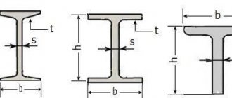
Of course, not only sheet metal parts are subjected to the bending process. Bends round and round parts. . square sections, bent and all rolled profiles - angles, channels, I-beams, pipes. However, cold bending of sheet metal parts is by far the most common.
To ensure minimum radii, parts are sometimes heated before bending. This increases the plasticity of the material. Using bending with a calibrating blow, it is ensured that the internal radius of the part becomes absolutely equal to the radius of the punch. With free V-shaped bending on a sheet bending machine, the internal radius in practice is greater than the radius of the punch. The more pronounced the spring properties of the part material are, the more different the internal radius of the part and the radius of the punch are from each other.
AutoPOL7 - a new tool for designing and unfolding sheet metal parts
Vitaly Kononov, Igor Karaulov
Capabilities of the AutoPOL7 software package
AutoPOL7 scanning capabilities
Calculation of developments and interface of the AutoPOL7 package
Generation of control programs for CNC machines, ability to export data in DXF format
AutoPOL7 as part of a unified system for technological preparation of production
The FCC Software (Sweden) AutoPOL7 program appeared on the Saprov firmament in 1998 and immediately attracted the attention of specialists with its wide capabilities in the field of development of scans and a relatively low price for programs of this class. FCC Software's new AutoPOL7 application includes a complete flattening program for engineered sheet metal parts.
There are two different versions of the AutoPOL7 application. The AutoPOL7DT software package for Autodesk Mechanical Desktop allows you to automatically create parametric models of products. You can also use the AutoPOL7 application for AutoCAD 2000.
New and enhanced flattening capabilities make AutoPOL7 one of the most advanced professional AutoCAD applications for sheet metal design. AutoPOL7 has been in development for many years. The program was based on the extensive experience of FCC Software engineers together with the most modern programming technology.
The use of computer technology in the development of this software package made it possible to create a product that guarantees models of the highest quality and accuracy. The use of this application will allow users to benefit from its implementation through the use of effective “seamless” integration with AutoCAD and Mechanical Desktop.
The combination of AutoPOL7 with Mechanical Desktop provides the latest computer technology for sheet metal design. There are several features that distinguish AutoPOL7 from other similar programs:
- expanded capabilities for deploying 3D structures;
- punching capabilities with preview;
- object-oriented editing of models;
- library of blanks for sheet metal products.
Features of the AutoPOL7 software package
The AutoPOL7 program has several advantages, which, no doubt, will immediately be noticed by specialists. The most important advantages are ease of use and efficient deployment procedure.
AutoPOL7 has a user-friendly interface that allows you to preview work results in real time using object-oriented model editing capabilities.
This program uses FCC Software's state-of-the-art computer aided design tools and today's best sheet metal development algorithms. AutoPOL7 makes it possible to easily design sheet metal parts and carry out their development, as well as generate the necessary working documentation.
The ease and simplicity of the program is amazing. One of the main goals in its development was to create an intuitive interface that allows even specialists with little computer experience to easily design sheet metal parts using AutoPOL7.
In addition, the program has effective tools and algorithms that can be used when creating sheet metal parts. Of all similar computer-aided design programs, only AutoPOL7 has such powerful development tools.
AutoPOL7 provides the development of spatial details of complex modern geometries with the same quality as more expensive similar programs from other companies, but with higher accuracy. In this case, the only limitation is that the unfolded objects must have the same curvature.
Another important feature of AutoPOL7 that deserves mention is the presence and ability to use a library of standard geometries, such as connecting pipes, transitions from rectangles to circles, etc.
When using other development programs, users will need to purchase additional modules with these capabilities for a separate fee, but in AutoPOL7 they are already included in the software package. In addition to all of the above, the program implements the following features and functions:
- Unfolding functions applicable to all types of solid models;
- working with surfaces created in AutoCAD;
- working with surfaces created in Mechanical Desktop;
- working with models imported from other CAD systems;
- the ability to update flat drawings of developments when changing the parameters of the original spatial model;
- function of automatic generation of box-shaped parts;
- unique tools for dynamic design;
- subroutines for perforating a product (perforation in planes and on curved sections) with a preview in dynamic mode: round holes, rounded holes, rectangular holes, holes with different profiles, selectable by the user;
- object-oriented editing of models and working drawings;
- sheet metal parts library;
- create outlines of sheet metal parts using polylines;
- lengthening the edges of a sheet of metal;
- automatic rounding of the edges of sheet metal parts;
- function for assembling sheet metal parts;
- subroutine for processing product contours: the ability to convert splines, connect polylines, optimize curves, set dimensions taking into account coordinates;
- dividing large drawings into separate parts;
- calculation of areas, weights and spatial angles;
- parametric generation of surface models in the standard AutoCAD environment.
AutoPOL7 scanning capabilities
Let's ask ourselves what types of models AutoPOL7 can deploy. The development functions in the program allow you to create developments of all types of 3D geometric models of uniform curvature.
Objects that can be selected for development are a variety of parts made using AutoCAD and Autodesk Mechanical Desktop: any three-dimensional spatial models, body parts, shells, NURBS surfaces, etc.
In addition, you can unfold any objects described by mathematical constraints: objects described by planes, cylindrical objects, conical, elliptical or spline surfaces. Using AutoPOL7 tools, developments can be constructed for geometric elements of double curvature.
Calculation of developments and interface of the AutoPOL7 package
AutoPOL7 has a modern, intuitive interface. The software package allows you to create flat drawings of part developments very quickly and with high accuracy. When creating drawings of part developments to take into account bending, the development subroutine uses the corresponding Kx-factor. To calculate sweep lengths, the program uses the compensation method.
AutoPOL7 uses the Kx factor to calculate bending tolerances. You can use the Kx factor formula according to DIN 6935 or the corresponding values from the material file. These values are experimental. They depend on the bending angle and the ratio of the internal radius to the sheet thickness.
AutoPOL7 has a material file with Kx-factor values, which allows, in most cases, to generate accurate developments of product models. However, the values of the Kx factor depend on many other parameters. Decreases in material strength, sheet thickness and the friction of the tool used to bend the sheet can result in a decrease in the Kx-factor value.
Therefore, users have the opportunity to change the values of the Kx-factor and independently expand existing libraries and knowledge bases. AutoPOL7 easily adds bend lines and bend angles to flat pattern drawings. AutoPOL7 is a user-configurable system based on user knowledge.
The program uses an intelligent learning solver, which, while working with the user, gradually “absorbs” his knowledge and experience.
Generation of control programs for CNC machines, ability to export data in DXF format
Can I use the geometry of a flattened part to create a NC program using my existing AutoCAD-integrated CAM application? Is it possible to export a DXF file of information to any standalone CAM program that uses this format? It is safe to say that AutoPOL7 implements all this, since the unfolded geometry contains objects and associated information in the AutoCAD data representation format. Sometimes it is necessary to transform objects such as splines and elliptic curves to generate a control program for a CNC machine in a custom CAM application. AutoPOL7 has a function that allows you to prepare product information for this. Splines and elliptical objects are converted to arcs and lines. Of particular interest is the use of models from AutoPOL7, obtained in the Autodesk Mechanical Desktop environment using Pathtrace's EdgeCAM program, to generate control codes for CNC machines. Like AutoPOL7, EdgeCAM is an application for Autodesk Mechanical Desktop and uses its graphics core as a geometric solid modeler. Therefore, working in the Mechanical Desktop environment with AutoPOL7, after completing the procedure for obtaining a flat pattern, an engineer can immediately, without leaving the Mechanical Desktop, transfer the received file over the network to another specialist to receive a control program for manufacturing this part. Using the same modeling platform ensures accurate transfer of data from one professional application to another without loss or distortion.
AutoPOL7 as part of a unified system for technological preparation of production
Thousands of users around the world enjoy working with AutoPOL7. AutoPOL7's user interface capabilities enable you to create a professional-oriented environment that helps increase design efficiency and increase productivity when working on sheet metal fabrication.
AutoPOL7 has all the benefits that come with ARX technology from Autodesk, Inc. and the Mechanical Desktop API. In addition, AutoPOL7 provides the ability to transfer information and product simulation results to MSC Software's Dytran software package.
Engineers have the opportunity to control the manufacturing process and manage the quality of the product already at the computer design stage.
This allows you to significantly shorten the cycle from design to obtaining a real metal product and save significant money due to the absence of defects in the product, as well as due to the absence of the need for modification or re-manufacturing of equipment. But we will talk about this in the next article.
"CAD and Graphics" 6'2000
The sweep calculation will be performed in MS Excel.
But the whole problem is that the neutral layer is not located in the middle of the metal section! For reference: the neutral layer is the surface of the arrangement of conditional metal fibers that do not stretch or compress when bent. Moreover, this surface is (sort of) not the surface of a circular cylinder. Some sources suggest that it is a parabolic cylinder...
Based on this formula, a program was created for calculating the development of sheet parts made of steel grades St3 and 10...20 in Excel.
In cells with light green and turquoise fill we write the original data. In a cell with a light yellow fill, we read the calculation result.
1. Write down the thickness of the sheet blank s in millimeters
to cell D 3: 5,0
2. the length of the first straight section L 1 in millimeters
to cell D 4: 40,0
3. the inner bend radius of the first section R 1 in millimeters
to cell D 5: 5,0
4. the bend angle of the first section a 1 in degrees
to cell D 6: 90,0
5. the length of the second straight section of the part L 2 in millimeters
to cell D 7: 40,0
6. That’s it, the result of the calculation is the length of the part development L in millimeters
in cell D 17: =D4+IF(D5=0;0;PI()/180*D6*D3/LN ((D5+D3)/D5))+ +D7+IF(D8=0;0;PI ()/180*D9*D3/LN ((D8+D3)/D8))+D10+ +IF(D11=0;0;PI()/180*D12*D3/LN ((D11+D3)/D11 ))+D13+ +IF(D14=0;0;PI()/180*D15*D3/LN ((D14+D3)/D14))+D16 =91.33
Using the proposed program, you can calculate the length of the development for parts with one bend - corners, with two bends - channels and Z-profiles, with three and four bends. If you need to calculate the development of a part with a large number of bends, then the program can be very easily modified to expand its capabilities.
An important advantage of the proposed program (unlike many similar ones) is the ability to specify different angles and bending radii at each step .
Does the program produce the “correct” results? Let's compare the obtained result with the results of calculations using the methodology outlined in the “Handbook of Mechanical Designer” by V.I. Anuriev and in the “Die Designer’s Handbook” by L.I. Rudman. Moreover, we will take into account only the curved section, since, I hope, all rectilinear sections are considered the same.
Let's check the example discussed above.
“According to the program”: 11.33 mm – 100.0%
“According to Anuriev”: 10.60 mm – 93.6%
“According to Rudman”: 11.20 mm – 98.9%
In our example, let's increase the bending radius R 1
twice - up to 10 mm. Once again we will make the calculation using three methods.
“According to the program”: 19.37 mm – 100.0%
“According to Anuriev”: 18.65 mm – 96.3%
“According to Rudman”: 19.30 mm – 99.6%
Thus, the proposed calculation method produces results that are 0.4%...1.1% more than “according to Rudman” and 6.4%...3.7% more than “according to Anuriev”. It is clear that the error will decrease significantly when we add straight sections.
“According to the program”: 99.37 mm – 100.0%
“According to Anuriev”: 98.65 mm – 99.3%
“According to Rudman”: 99.30 mm – 99.9%
Perhaps Rudman compiled his tables using the same formula that I use, but with the error of a slide rule... Of course, today it’s the twenty-first century, and it’s somehow not convenient to scour the tables!
In conclusion, I will add a “fly in the ointment”. The length of the sweep is a very important and “subtle” point! If the designer of a bent part (especially a high-precision part (0.1 mm)) hopes to accurately determine it by calculation and the first time, then he hopes in vain. In practice, a lot of factors will interfere with the bending process - direction of rolling, tolerance on metal thickness, thinning of the section at the bending point, “trapezoidal section”, temperature of the material and equipment, presence or absence of lubricant in the bending zone, mood of the bender... In short, if the batch of parts is large and is expensive - check with practical experiments the length of the sweep on several samples . And only after receiving a suitable part, cut the blanks for the entire batch. And for the manufacture of blanks for these samples, the accuracy provided by the development calculation program is more than enough!
Calculation programs “according to Anuriev” and “according to Rudman” in Excel can be found on the Internet.
I look forward to your comments, colleagues.
For those who RESPECT the author’s work, you can download the file AFTER SUBSCRIBING TO ANNOUNCEMENTS OF ARTICLES (the subscription form is just below and at the top of the page).
For the REST - you can download it just like that.
Link to download the file: raschet-dliny-razvertki (xls 36.5KB).
The topic is continued in the article about the K-factor.
Read about the calculation of development when bending pipes and rods here.
Source
Device for marking pipes. Calculation and production of a template - Equipment
In large procurement workshops, marking and cutting of pipes is carried out on a marking and cutting unit, which makes it possible to obtain pipeline parts with a tolerance of ± 1 mm.
In small procurement workshops and at the installation site, pipe marking is carried out on marking racks using conventional marking and measuring tools: rulers, tape measures, scribers, templates, etc.
Marking the pipe consists of determining its blank length and drawing the necessary axes. Having marked the pipe for cutting, the beginnings of all bends, holes for inserting taps and tees are marked on it.
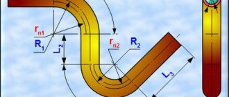
To manufacture a bent bend and determine the length of the workpiece, the radius (R) and angle (a) of the bend of the pipe, the length of the free ends or the length of the straight section between the bends must be known. The length of the workpiece (Fig. 1) is determined by the formula
Where LTotal is the length of the workpiece, m;
L= π/180*αR – length of the curved part, m;
L1 = L – S – length of the straight section, m;
L2 = L1-S-length of the second straight section, m; .
Figure 1. Marking the pipe for bending
- a – marking of the outlet;
- b – pipeline section.
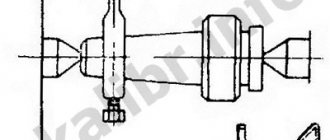
When two pipes intersect, the cutting tee is marked using a device that is made on a sheet of thick paper. First, the intersection of two pipes is drawn in two projections and in full size, as shown in Fig. 2. A semicircle is built on the embedded part of the pipe, which is usually divided into six parts (points 1, 2, 3, 4, 5, 6). Straight lines parallel to the axis of the pipe are drawn through these points. On the second projection, similar constructions are made, straight lines are drawn until they intersect with the contour of the pipe into which the insertion needs to be made (points 0, 1, 2, 3). Drawing parallel lines from these points, as shown in the figure, we obtain points 0l, 1l, 2l, 3l, 4l, 5l, 6l.
Rice. 5. Marking the intersection of two pipes
- a – built for making a template;
- b – template.
Determining the development length when bending
Elements of the workpiece located in the deformable zone and adjacent to the inner surface of the bent part (from the punch side) are subject to compression, and those adjacent to the outer surface (from the matrix side) are subject to tension. Between the stretched and compressed fibers there is a neutral line whose length does not change (Drawing 106).
Crap. 106
The radius of the neutral line R in mm (drawing 106) is determined by the formula
where r is the bending radius, mm;
s—material thickness mm;
x is a coefficient, the value of which depends on the ratio r/s (Table 48).
Table 48
When curling hinges (loops), due to the presence of external friction forces that prevent deformation, the coefficient x is determined from the table. 48a.
Table 48a
The development length of the bending part Lр in mm (Fig. 107) is determined by the formula
R1; R2; R3 are the radii of the neutral line, determined by formula (46).
Crap. 107
When bending materials over 3 mm thick at an angle of 90° with a bending radius r≤s, the radius of the neutral line R, calculated according to formula (46), must be adjusted to the value R1 (Fig. 108), based on the condition of material integrity and mating points a and a1 of a curved section of radius R1 with straight lines a-a and a1-a1 passing through the middle of the thickness s. In section C-C1, the dotted line shows the outer contour in the calculation without taking into account the thinning of the material. Due to thinning during bending, the thickness s1 in this area is less than the original s.
Formulas
Formula for calculating Y values:
Yi = D * tan(α) * sin (i * (180 / n))
, here:
i
- point number,
α
- section angle,
n
- number of scan points,
D
- cylinder diameter;
Formula for calculating X values:
Xi = ((π * R 2 ) / n) * i
, here:
i
- point number,
α
- section angle,
n
- number of scan points,
R
- cylinder radius,
π
- Pi number (note 3.14);
Source
Guidelines for laboratory work.
Development of a technological process for manufacturing parts using sheet stamping: Method. Instructions / Compiled by Gurchenkov N.I., RUsanov E.V., Afanasyev E.V. – Tolyatti: TolPI, 1996.
Individual tasks are presented and the procedure for developing a technological process and selecting a sample for cutting and forming by sheet stamping is given.
For special students 1201, 1202, 1205, 1206, 1501, 1502, 1505, 1705, 1808, 2103.
Compiled by: Gurchenkov N.I., Rusanov E.A., Afanasyev E.V.
Scientific editors: Doctor of Technical Sciences, Professor Tikhonov A.K.,
Doctor of Physical and Mathematical Sciences, Professor Vyboishchik M.A.
Approved by the editorial and publishing section of the methodological council of the institute.
Tolyatti Polytechnic Institute, 1996.
Calculation of sweep length
As I promised in the comments to the article “Calculating the force of a sheet metal bender,” today we’ll talk about calculating the length of the development of a part bent from sheet metal. Of course, not only sheet metal parts are subjected to the bending process. Bends round and round parts. . square sections, bent and all rolled profiles - angles, channels, I-beams, pipes. However, cold bending of sheet metal parts is by far the most common.
To ensure minimum radii, parts are sometimes heated before bending. This increases the plasticity of the material. Using bending with a calibrating blow, it is ensured that the internal radius of the part becomes absolutely equal to the radius of the punch. With free V-shaped bending on a sheet bending machine, the internal radius in practice is greater than the radius of the punch. The more pronounced the spring properties of the part material are, the more different the internal radius of the part and the radius of the punch are from each other.
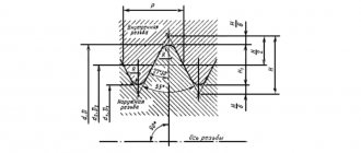
The figure below shows a corner bent from a sheet of thickness s and width b . You need to find the sweep length.
How to correctly calculate the dimensions of the shell (schuber) layout?
Typically, the work of preparing or finalizing original layouts for various types of packaging is undertaken by our pre-press department. But there are times when customers or designers want to independently compose a layout for printing and ask us: “How to correctly calculate the dimensions of the shell/sleeve so that the contents fit into the cardboard package and do not fall out of it?”
Let's take a closer look at what this popular type of packaging is and what needs to be taken into account when calculating the layout dimensions.
Basic packaging requirements
What a shell is and how it differs from a shuber is discussed in detail on the page “SHUERS AND WELLS” >>
The shell (popularly known as “shuber”) should be:
Let's talk about the last two points. The matter is, in general, simple, but there are nuances.
How to calculate the dimensions of a rectangular shell layout
The simplest design is a rectangular (unfolded) shell.
She has three characteristics:
Calculation of shell length
1. Determine the sum of the lengths of all surfaces
Take the box on which you are going to put the future shell, and measure the length of all surfaces that the packaging will “hug”. Take measurements at right angles to the edges. Let's sum up all the values.
2. Increase for loose fit
3. Valve for gluing
The standard valve size is 12-18 mm.
Sometimes, instead of gluing, a self-assembling lock is used, which snaps into place at the place where the product is packaged. The lock takes about 30 mm over the entire length, this should also be taken into account.
We sum up the values from three points and get the length of the shell:
Shell length = sum of lengths of all surfaces + increase + valve
Shell width
Width is that part of the product packaging that the shuber will close. Here it’s up to you to decide whether to cover the entire package or make the cardboard shell narrower so that the product is visible.
Shell thickness
This is the thickness of the cardboard plus lamination, if any.
When making preliminary calculations, the thickness of the cardboard can be ignored; let the printing house figure it out